
Manual
Page 1
...of a button, X.H.D helps to expand its capacity. B. Setting Up a RAID-Ready System Step 1: Configure the system BIOS Enter the system BIOS Setup program, set eXtreme Hard Drive (X.H.D) under the Integrated Peripherals menu to Enabled to automatically and quickly set up all ...To automatically set up a RAID 0 array: Click Auto to enable RAID for complex and time-consuming configurations. eXtreme Hard Drive (X.H.D) With GIGABYTE eXtreme Hard Drive (X.H.D)(Note 1), users can build a RAID 0, RAID 1, or other supported RAID array depending on your needs and hardware components...
...of a button, X.H.D helps to expand its capacity. B. Setting Up a RAID-Ready System Step 1: Configure the system BIOS Enter the system BIOS Setup program, set eXtreme Hard Drive (X.H.D) under the Integrated Peripherals menu to Enabled to automatically and quickly set up all ...To automatically set up a RAID 0 array: Click Auto to enable RAID for complex and time-consuming configurations. eXtreme Hard Drive (X.H.D) With GIGABYTE eXtreme Hard Drive (X.H.D)(Note 1), users can build a RAID 0, RAID 1, or other supported RAID array depending on your needs and hardware components...

Manual
Page 2
Configuring the Smart TPM Utility 18 4.1. Creating a Bluetooth Cell Phone Key 19 4.3. Other Features...21 - 2 - Configuring the System BIOS 3 2. Initializing the TPM chip 5 3.1. Creating a USB Key 18 4.2. Other Bluetooth Settings 21 4.4. Initializing the TPM Chip with the Smart TPM Utility 5 3.2. Advanced Mode...8 4. Installing the Smart TPM Utility 4 3. Installing the Infineon TPM Driver 4 2.2. Installing the Infineon TPM Driver and the Smart TPM Utility 4 2.1. Table of Contents TPM Configuration Procedure 3 1.
Configuring the Smart TPM Utility 18 4.1. Creating a Bluetooth Cell Phone Key 19 4.3. Other Features...21 - 2 - Configuring the System BIOS 3 2. Initializing the TPM chip 5 3.1. Creating a USB Key 18 4.2. Other Bluetooth Settings 21 4.4. Initializing the TPM Chip with the Smart TPM Utility 5 3.2. Advanced Mode...8 4. Installing the Smart TPM Utility 4 3. Installing the Infineon TPM Driver 4 2.2. Installing the Infineon TPM Driver and the Smart TPM Utility 4 2.1. Table of Contents TPM Configuration Procedure 3 1.

Manual
Page 3
... TPM driver and the Smart TPM utility 3. Step 1: As the computer starts, enter the BIOS Setup program. Be sure to the Security Chip Configuration menu and the following screen will become inaccessible.... TPM Configuration Procedure To enable the TPM, follow the steps below in the BIOS main menu to display this setting) to activate the TPM chip. To activate the TPM chip, ...set the User Password in the BIOS Setup program. - 3 - CMOS Setup Utility-Copyright (C) 1984-2009 Award Software Security Chip Configuration Security...
... TPM driver and the Smart TPM utility 3. Step 1: As the computer starts, enter the BIOS Setup program. Be sure to the Security Chip Configuration menu and the following screen will become inaccessible.... TPM Configuration Procedure To enable the TPM, follow the steps below in the BIOS main menu to display this setting) to activate the TPM chip. To activate the TPM chip, ...set the User Password in the BIOS Setup program. - 3 - CMOS Setup Utility-Copyright (C) 1984-2009 Award Software Security Chip Configuration Security...

Manual
Page 5
... configured as the Smart TPM user key. You will be able to access/close your own password. Initializing the TPM chip After configuring the system BIOS and installing the driver software, the Infineon Security Platform icon , which your PSD will be saved. Be sure to memorize this password because it to...
... configured as the Smart TPM user key. You will be able to access/close your own password. Initializing the TPM chip After configuring the system BIOS and installing the driver software, the Infineon Security Platform icon , which your PSD will be saved. Be sure to memorize this password because it to...

Manual
Page 6
... TPM is 2 GB. This depends on drive drop-down list of my PSD box. To generate a new password, click Generate. 2. Enter the password in the BIOS Setup program. • This password incorporates the functionalities of the "Owner Password," "User Password," "Emergency Recovery Token Password," and "Password Reset Token Password" of the...
... TPM is 2 GB. This depends on drive drop-down list of my PSD box. To generate a new password, click Generate. 2. Enter the password in the BIOS Setup program. • This password incorporates the functionalities of the "Owner Password," "User Password," "Emergency Recovery Token Password," and "Password Reset Token Password" of the...

Manual
Page 7
... the TPM chip and the setups of the TPM User Password, your cell phone for the USB flash drive(s) that you plug in the system BIOS. Then select the cell phone that on your cell phone. Then enter the same passkey on your PSD, and the Smart TPM user key(s). - 7 - Step... Bluetooth enabled cell phone(s). Selecting the Enable Backup to use as the portable Smart TPM user key and a screen similar to that you want to BIOS check box will overwrite the former. 2. If more than one USB flash drive at the same time. You can select more than one user stores...
... the TPM chip and the setups of the TPM User Password, your cell phone for the USB flash drive(s) that you plug in the system BIOS. Then select the cell phone that on your cell phone. Then enter the same passkey on your PSD, and the Smart TPM user key(s). - 7 - Step... Bluetooth enabled cell phone(s). Selecting the Enable Backup to use as the portable Smart TPM user key and a screen similar to that you want to BIOS check box will overwrite the former. 2. If more than one USB flash drive at the same time. You can select more than one user stores...

Manual
Page 18
...an easy-to-use software interface to use as shown below. In addition, users can create more than one user uses the "Enable Bacup to BIOS" function to the Bluetooth cell phone or plugging in the notification area to display the menu as the portable user key. (If the screen ... access/close their PSD data by simply connecting to store their encrypted TPM User Passwords in the BIOS, the latter will render the files encrypted via the TPM unable to launch the Smart TPM utility. GIGABYTE is not liable for loss of encrypted data as a result of complicated configurations. Creating a USB ...
...an easy-to-use software interface to use as shown below. In addition, users can create more than one user uses the "Enable Bacup to BIOS" function to the Bluetooth cell phone or plugging in the notification area to display the menu as the portable user key. (If the screen ... access/close their PSD data by simply connecting to store their encrypted TPM User Passwords in the BIOS, the latter will render the files encrypted via the TPM unable to launch the Smart TPM utility. GIGABYTE is not liable for loss of encrypted data as a result of complicated configurations. Creating a USB ...

Manual
Page 19
... want to use as the Smart TPM user key on your motherboard includes a Bluetooth receiver and turn off or reset your PSD by plugging in BIOS Setup and then set earlier and click OK to complete creating the USB key. To be locked. Step 3: Enter the TPM User Password that you...
... want to use as the Smart TPM user key on your motherboard includes a Bluetooth receiver and turn off or reset your PSD by plugging in BIOS Setup and then set earlier and click OK to complete creating the USB key. To be locked. Step 3: Enter the TPM User Password that you...
Manual
Page 3
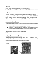
... CO., LTD. For instructions on how to their respective owners. The trademarks mentioned in any form or by GIGABYTE without GIGABYTE's prior written permission. For detailed product information, carefully read or download the information on/from the Support&Downloads\Motherboard...\Technology Guide page on your motherboard revision before updating motherboard BIOS, drivers, or when looking for technical information. For product-related information, check on our website at: http://www.gigabyte.com.tw Identifying Your Motherboard Revision The revision number on our ...
... CO., LTD. For instructions on how to their respective owners. The trademarks mentioned in any form or by GIGABYTE without GIGABYTE's prior written permission. For detailed product information, carefully read or download the information on/from the Support&Downloads\Motherboard...\Technology Guide page on your motherboard revision before updating motherboard BIOS, drivers, or when looking for technical information. For product-related information, check on our website at: http://www.gigabyte.com.tw Identifying Your Motherboard Revision The revision number on our ...
Manual
Page 4
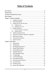
Table of Contents Box Contents...6 Optional Items...6 GA-P55A-UD5 Motherboard Layout 7 Block Diagram...8 Chapter 1 Hardware Installation 9 1-1 Installation Precautions 9 1-2 Product Specifications 10 1-3 Installing the CPU and CPU Cooler 13 1-3-1 ...1-7 Back Panel Connectors 20 1-8 Onboard LEDs and Buttons 22 1-9 Internal Connectors 24 Chapter 2 BIOS Setup 35 2-1 Startup Screen 36 2-2 The Main Menu 37 2-3 MB Intelligent Tweaker(M.I.T 39 2-4 Standard CMOS Features 49 2-5 Advanced BIOS Features 51 2-6 Integrated Peripherals 53 2-7 Power Management Setup 57 2-8 PC Health Status 59 ...
Table of Contents Box Contents...6 Optional Items...6 GA-P55A-UD5 Motherboard Layout 7 Block Diagram...8 Chapter 1 Hardware Installation 9 1-1 Installation Precautions 9 1-2 Product Specifications 10 1-3 Installing the CPU and CPU Cooler 13 1-3-1 ...1-7 Back Panel Connectors 20 1-8 Onboard LEDs and Buttons 22 1-9 Internal Connectors 24 Chapter 2 BIOS Setup 35 2-1 Startup Screen 36 2-2 The Main Menu 37 2-3 MB Intelligent Tweaker(M.I.T 39 2-4 Standard CMOS Features 49 2-5 Advanced BIOS Features 51 2-6 Integrated Peripherals 53 2-7 Power Management Setup 57 2-8 PC Health Status 59 ...
Manual
Page 5
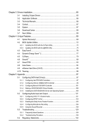
... 66 3-4 Contact...67 3-5 System...67 3-6 Download Center 68 3-7 New Utilities...68 Chapter 4 Unique Features 69 4-1 Xpress Recovery2 69 4-2 BIOS Update Utilities 72 4-2-1 Updating the BIOS with the Q-Flash Utility 72 4-2-2 Updating the BIOS with the @BIOS Utility 75 4-3 EasyTune 6...76 4-4 Dynamic Energy Saver™ 2 77 4-5 Q-Share...79 4-6 Smart 6™ ...80 4-7 Smart TPM ...83 4-8 Auto...
... 66 3-4 Contact...67 3-5 System...67 3-6 Download Center 68 3-7 New Utilities...68 Chapter 4 Unique Features 69 4-1 Xpress Recovery2 69 4-2 BIOS Update Utilities 72 4-2-1 Updating the BIOS with the Q-Flash Utility 72 4-2-2 Updating the BIOS with the @BIOS Utility 75 4-3 EasyTune 6...76 4-4 Dynamic Energy Saver™ 2 77 4-5 Q-Share...79 4-6 Smart 6™ ...80 4-7 Smart TPM ...83 4-8 Auto...
Manual
Page 8
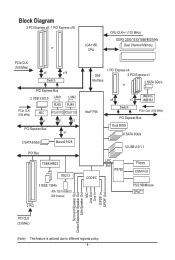
... 1 PCI Express x4 3 PCI Express x1 2 SATA 3Gb/s or Intel® P55 JMicron x4 x1 JMB362 Switch PCIe CLK (100 MHz) PCI Express Bus Dual BIOS 6 SATA 3Gb/s 12 USB 2.0/1.1 CODEC LPC Bus IT8720 Floppy COM Port PS/2 KB/Mouse TPM(Note) PCI CLK (33 MHz) Surround Speaker Out Center/Subwoofer...
... 1 PCI Express x4 3 PCI Express x1 2 SATA 3Gb/s or Intel® P55 JMicron x4 x1 JMB362 Switch PCIe CLK (100 MHz) PCI Express Bus Dual BIOS 6 SATA 3Gb/s 12 USB 2.0/1.1 CODEC LPC Bus IT8720 Floppy COM Port PS/2 KB/Mouse TPM(Note) PCI CLK (33 MHz) Surround Speaker Out Center/Subwoofer...
Manual
Page 12
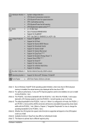
Hardware Installation - 12 - Hardware Monitor w w w w w w BIOS w w w w Unique Features w w w w w w w w w w w w w Bundled Software w System voltage detection CPU/System temperature detection ... limitation, when more than 4 GB of licensed AWARD BIOS Support for DualBIOS™ PnP 1.0a, DMI 2.0, SM BIOS 2.4, ACPI 1.0b Support for @BIOS Support for Q-Flash Support for Xpress BIOS Rescue Support for Download Center Support for Xpress Install Support...
Hardware Installation - 12 - Hardware Monitor w w w w w w BIOS w w w w Unique Features w w w w w w w w w w w w w Bundled Software w System voltage detection CPU/System temperature detection ... limitation, when more than 4 GB of licensed AWARD BIOS Support for DualBIOS™ PnP 1.0a, DMI 2.0, SM BIOS 2.4, ACPI 1.0b Support for @BIOS Support for Q-Flash Support for Xpress BIOS Rescue Support for Download Center Support for Xpress Install Support...
Manual
Page 16
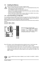
...is installed, be sure to install it is recommended that memory of the same capacity, brand, speed, and chips be used . (Go to GIGABYTE's website for optimum performance. If you begin to install the memory: • Make sure that memory of the memory. DS/SS Four Modules DS...enabling Dual Channel mode with two or four memory modules, it in Dual Channel mode. 1. If only one DDR3 memory module is installed, the BIOS will double the original memory bandwidth. 1-4 Installing the Memory Read the following guidelines before you are divided into two channels and each channel has ...
...is installed, be sure to install it is recommended that memory of the same capacity, brand, speed, and chips be used . (Go to GIGABYTE's website for optimum performance. If you begin to install the memory: • Make sure that memory of the memory. DS/SS Four Modules DS...enabling Dual Channel mode with two or four memory modules, it in Dual Channel mode. 1. If only one DDR3 memory module is installed, the BIOS will double the original memory bandwidth. 1-4 Installing the Memory Read the following guidelines before you are divided into two channels and each channel has ...
Manual
Page 18
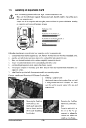
... chassis back panel with your expansion card in the slot and does not rock. • Removing the Card from the slot. If necessary, go to BIOS Setup to release the card and then pull the card straight up from the PCIEX16_1 Slot: Gently push back on the lever on the card... Removing a PCI Express Graphics Card: • Installing a Graphics Card: Gently push down on the top edge of the PCI Express slot to make any required BIOS changes for your computer. Install the driver provided with the slot, and press down on the card until it is securely seated in the expansion...
... chassis back panel with your expansion card in the slot and does not rock. • Removing the Card from the slot. If necessary, go to BIOS Setup to release the card and then pull the card straight up from the PCIEX16_1 Slot: Gently push back on the lever on the card... Removing a PCI Express Graphics Card: • Installing a Graphics Card: Gently push down on the top edge of the PCI Express slot to make any required BIOS changes for your computer. Install the driver provided with the slot, and press down on the card until it is securely seated in the expansion...
Manual
Page 22
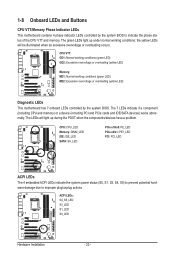
...under normal working conditions (green LED) MD2: Excessive overvoltage or overloading (yellow LED) Diagnostic LEDs This motherboard has 7 onboard LEDs controlled by the system BIOS to improper plug/unplug actions. CPU VTT: GD1: Normal working conditions (green LED) GD2: Excessive overvoltage or overloading (yellow LED) Memory: MD1: Normal... - 22 - 1-8 Onboard LEDs and Buttons CPU VTT/Memory Phase Indicator LEDs This motherboard contains 4 phase indicator LEDs controlled by the system BIOS. The green LEDs light up during the POST when the components/devices have a problem.
...under normal working conditions (green LED) MD2: Excessive overvoltage or overloading (yellow LED) Diagnostic LEDs This motherboard has 7 onboard LEDs controlled by the system BIOS to improper plug/unplug actions. CPU VTT: GD1: Normal working conditions (green LED) GD2: Excessive overvoltage or overloading (yellow LED) Memory: MD1: Normal... - 22 - 1-8 Onboard LEDs and Buttons CPU VTT/Memory Phase Indicator LEDs This motherboard contains 4 phase indicator LEDs controlled by the system BIOS. The green LEDs light up during the POST when the components/devices have a problem.
Manual
Page 23
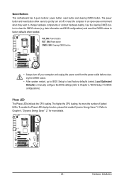
... button and reset button allow users to quickly turn off or reset the computer in an open-case environment when they want to Chapter 2, "BIOS Setup," for more the number of lighted LEDs. The higher the CPU loading, the more details. - 23 - Phase LED The Phase LEDs indicate...power cord from the power outlet before clearing the CMOS values. • After system restart, go to BIOS Setup to load factory defaults (select Load Optimized Defaults) or manually configure the BIOS settings (refer to change hardware components or conduct hardware testing. To enable the Phase LED display function, ...
... button and reset button allow users to quickly turn off or reset the computer in an open-case environment when they want to Chapter 2, "BIOS Setup," for more the number of lighted LEDs. The higher the CPU loading, the more details. - 23 - Phase LED The Phase LEDs indicate...power cord from the power outlet before clearing the CMOS values. • After system restart, go to BIOS Setup to load factory defaults (select Load Optimized Defaults) or manually configure the BIOS settings (refer to change hardware components or conduct hardware testing. To enable the Phase LED display function, ...

Manual
Page 29
...of power switch, reset switch, power LED, hard drive activity LED, speaker and etc. When connecting your system using the power switch (refer to Chapter 2, "BIOS Setup," "Power Management Setup," for information about beep codes. • HD (Hard Drive Activity LED, Blue) Connects to the chassis intrusion switch/sensor on ...Gray): Connects to the hard drive activity LED on the chassis front panel. The LED S0 On is on when the system is detected, the BIOS may issue beeps in S3/S4 sleep S3/S4/S5 Off state or powered off your chassis front panel module to the power status indicator...
...of power switch, reset switch, power LED, hard drive activity LED, speaker and etc. When connecting your system using the power switch (refer to Chapter 2, "BIOS Setup," "Power Management Setup," for information about beep codes. • HD (Hard Drive Activity LED, Blue) Connects to the chassis intrusion switch/sensor on ...Gray): Connects to the hard drive activity LED on the chassis front panel. The LED S0 On is on when the system is detected, the BIOS may issue beeps in S3/S4 sleep S3/S4/S5 Off state or powered off your chassis front panel module to the power status indicator...
Manual
Page 33
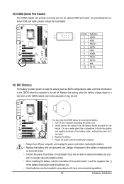
... 2 1 NDCD- 2 NSIN 3 NSOUT 4 NDTR- 5 GND 6 NDSR- 7 NRTS- 8 NCTS- 9 NRI- 10 No Pin 19) BAT (Battery) The battery provides power to keep the values (such as BIOS configurations, date, and time information) in the power cord and restart your computer. • Always turn off . Plug in the CMOS when the computer is...
... 2 1 NDCD- 2 NSIN 3 NSOUT 4 NDTR- 5 GND 6 NDSR- 7 NRTS- 8 NCTS- 9 NRI- 10 No Pin 19) BAT (Battery) The battery provides power to keep the values (such as BIOS configurations, date, and time information) in the power cord and restart your computer. • Always turn off . Plug in the CMOS when the computer is...
Manual
Page 35
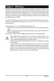
...to the "Load Optimized Defaults" section in this chapter or introductions of the clearing CMOS button/battery in the CMOS on . Chapter 2 BIOS Setup BIOS (Basic Input and Output System) records hardware parameters of the system in Chapter 1 for the beep codes description. • It is ... or to quickly and easily upgrade or back up BIOS without entering the operating system. • @BIOS is recommended that searches and downloads the latest version of the BIOS Setup program. To upgrade the BIOS, use either the GIGABYTE Q-Flash or @BIOS utility. • Q-Flash allows the user to ...
...to the "Load Optimized Defaults" section in this chapter or introductions of the clearing CMOS button/battery in the CMOS on . Chapter 2 BIOS Setup BIOS (Basic Input and Output System) records hardware parameters of the system in Chapter 1 for the beep codes description. • It is ... or to quickly and easily upgrade or back up BIOS without entering the operating system. • @BIOS is recommended that searches and downloads the latest version of the BIOS Setup program. To upgrade the BIOS, use either the GIGABYTE Q-Flash or @BIOS utility. • Q-Flash allows the user to ...


