
Manual
Page 1
... utiltiy After installing the operating system, insert the motherboard driver disk. Setting Up a RAID-Ready System Step 1: Configure the system BIOS Enter the system BIOS Setup program, set up a RAID array: (Note 3): Click Manual to access the Intel Matrix Storage Console, with a simple click...Enabled to enable RAID for complex and time-consuming configurations. Using GIGABYTE eXtreme Hard Drive (X.H.D) Instructions:(Note 2) Before launching X.H.D, make sure the new drive is added. eXtreme Hard Drive (X.H.D) With GIGABYTE eXtreme Hard Drive (X.H.D)(Note 1), users can go to the ...
... utiltiy After installing the operating system, insert the motherboard driver disk. Setting Up a RAID-Ready System Step 1: Configure the system BIOS Enter the system BIOS Setup program, set up a RAID array: (Note 3): Click Manual to access the Intel Matrix Storage Console, with a simple click...Enabled to enable RAID for complex and time-consuming configurations. Using GIGABYTE eXtreme Hard Drive (X.H.D) Instructions:(Note 2) Before launching X.H.D, make sure the new drive is added. eXtreme Hard Drive (X.H.D) With GIGABYTE eXtreme Hard Drive (X.H.D)(Note 1), users can go to the ...
Manual
Page 3
... read the Quick Installation Guide included with the product. Check your motherboard looks like this manual may be made by GIGABYTE without GIGABYTE's prior written permission. The trademarks mentioned in any means without prior notice. No part of this manual is protected by...features, read or download the information on/from the Support&Downloads\Motherboard\Technology Guide page on your motherboard revision before updating motherboard BIOS, drivers, or when looking for technical information. For instructions on how to their respective owners. Changes to assist in this...
... read the Quick Installation Guide included with the product. Check your motherboard looks like this manual may be made by GIGABYTE without GIGABYTE's prior written permission. The trademarks mentioned in any means without prior notice. No part of this manual is protected by...features, read or download the information on/from the Support&Downloads\Motherboard\Technology Guide page on your motherboard revision before updating motherboard BIOS, drivers, or when looking for technical information. For instructions on how to their respective owners. Changes to assist in this...
Manual
Page 4
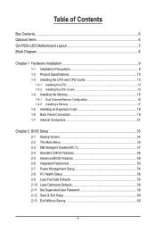
Table of Contents Box Contents...6 Optional Items...6 GA-P55A-UD3 Motherboard Layout 7 Block Diagram...8 Chapter 1 Hardware Installation 9 1-1 Installation Precautions 9 1-2 Product Specifications 10 1-3 Installing the CPU and CPU Cooler 13 ...1-5 Installing an Expansion Card 18 1-6 Back Panel Connectors 19 1-7 Internal Connectors 21 Chapter 2 BIOS Setup 33 2-1 Startup Screen 34 2-2 The Main Menu 35 2-3 MB Intelligent Tweaker(M.I.T 37 2-4 Standard CMOS Features 46 2-5 Advanced BIOS Features 48 2-6 Integrated Peripherals 50 2-7 Power Management Setup 54 2-8 PC Health Status 56 2-9...
Table of Contents Box Contents...6 Optional Items...6 GA-P55A-UD3 Motherboard Layout 7 Block Diagram...8 Chapter 1 Hardware Installation 9 1-1 Installation Precautions 9 1-2 Product Specifications 10 1-3 Installing the CPU and CPU Cooler 13 ...1-5 Installing an Expansion Card 18 1-6 Back Panel Connectors 19 1-7 Internal Connectors 21 Chapter 2 BIOS Setup 33 2-1 Startup Screen 34 2-2 The Main Menu 35 2-3 MB Intelligent Tweaker(M.I.T 37 2-4 Standard CMOS Features 46 2-5 Advanced BIOS Features 48 2-6 Integrated Peripherals 50 2-7 Power Management Setup 54 2-8 PC Health Status 56 2-9...

Manual
Page 5
... 62 3-4 Contact...63 3-5 System...63 3-6 Download Center 64 3-7 New Utilities...64 Chapter 4 Unique Features 65 4-1 Xpress Recovery2 65 4-2 BIOS Update Utilities 68 4-2-1 Updating the BIOS with the Q-Flash Utility 68 4-2-2 Updating the BIOS with the @BIOS Utility 71 4-3 EasyTune 6...72 4-4 Dynamic Energy Saver™ 2 73 4-5 Q-Share...75 4-6 Smart 6™ ...76 4-7 Auto Green...79 4-8 eXtreme...
... 62 3-4 Contact...63 3-5 System...63 3-6 Download Center 64 3-7 New Utilities...64 Chapter 4 Unique Features 65 4-1 Xpress Recovery2 65 4-2 BIOS Update Utilities 68 4-2-1 Updating the BIOS with the Q-Flash Utility 68 4-2-2 Updating the BIOS with the @BIOS Utility 71 4-3 EasyTune 6...72 4-4 Dynamic Energy Saver™ 2 73 4-5 Q-Share...75 4-6 Smart 6™ ...76 4-7 Auto Green...79 4-8 eXtreme...

Manual
Page 8
... 3.0/2.0 LAN RJ45 NEC RTL8111D x1 x1 PCI Express Bus x1 2 SATA 6Gb/s Marvell 9128 Intel® P55 x1 x4 Switch x1 PCI Express Bus Dual BIOS 6 SATA 3Gb/s PCI Bus 12 USB 2.0/1.1 IT8213 ATA-133/100/66/33 IDE Channel CODEC LPC Bus IT8720 Floppy COM Port PS/2 KB/Mouse 3 PCI...
... 3.0/2.0 LAN RJ45 NEC RTL8111D x1 x1 PCI Express Bus x1 2 SATA 6Gb/s Marvell 9128 Intel® P55 x1 x4 Switch x1 PCI Express Bus Dual BIOS 6 SATA 3Gb/s PCI Bus 12 USB 2.0/1.1 IT8213 ATA-133/100/66/33 IDE Channel CODEC LPC Bus IT8720 Floppy COM Port PS/2 KB/Mouse 3 PCI...
Manual
Page 12
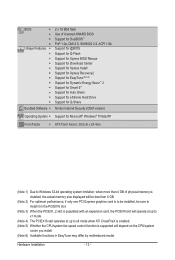
... Features w w w w w w w w w w w w Bundled Software w 2 x 16 Mbit flash Use of licensed AWARD BIOS Support for DualBIOS™ PnP 1.0a, DMI 2.0, SM BIOS 2.4, ACPI 1.0b Support for @BIOS Support for Q-Flash Support for Xpress BIOS Rescue Support for Download Center Support for Xpress Install Support for Xpress Recovery2 Support for EasyTune (Note 6) Support for Dynamic Energy Saver...
... Features w w w w w w w w w w w w Bundled Software w 2 x 16 Mbit flash Use of licensed AWARD BIOS Support for DualBIOS™ PnP 1.0a, DMI 2.0, SM BIOS 2.4, ACPI 1.0b Support for @BIOS Support for Q-Flash Support for Xpress BIOS Rescue Support for Download Center Support for Xpress Install Support for Xpress Recovery2 Support for EasyTune (Note 6) Support for Dynamic Energy Saver...

Manual
Page 16
... used . (Go to prevent hardware damage. • Memory modules have a foolproof design. The four DDR3 memory sockets are unable to install it is installed, the BIOS will double the original memory bandwidth. DS/SS - - After the memory is recommended that memory of the memory. DS/SS Four Modules DS/SS DS... the following guidelines before you are divided into two channels and each channel has two memory sockets as following guidelines before installing the memory to GIGABYTE's website for optimum performance.
... used . (Go to prevent hardware damage. • Memory modules have a foolproof design. The four DDR3 memory sockets are unable to install it is installed, the BIOS will double the original memory bandwidth. DS/SS - - After the memory is recommended that memory of the memory. DS/SS Four Modules DS/SS DS... the following guidelines before you are divided into two channels and each channel has two memory sockets as following guidelines before installing the memory to GIGABYTE's website for optimum performance.

Manual
Page 18
... from the slot. Hardware Installation - 18 - PCI Express x1 Slot PCI Express x16 Slot PCI Slot Follow the steps below to make any required BIOS changes for your expansion card in the slot and does not rock. • Removing the Card: Press the white latch at the end of the... card until it is fully seated in your computer. If necessary, go to BIOS Setup to correctly install your expansion card(s). 7. Remove the metal slot cover from the power outlet before you begin to prevent hardware damage. Make sure...
... from the slot. Hardware Installation - 18 - PCI Express x1 Slot PCI Express x16 Slot PCI Slot Follow the steps below to make any required BIOS changes for your expansion card in the slot and does not rock. • Removing the Card: Press the white latch at the end of the... card until it is fully seated in your computer. If necessary, go to BIOS Setup to correctly install your expansion card(s). 7. Remove the metal slot cover from the power outlet before you begin to prevent hardware damage. Make sure...

Manual
Page 25
... power cord before replacing the battery. • Replace the battery with local environmental regulations. - 25 - The battery provides power to keep the values (such as BIOS configurations, date, and time information) in the power cord and restart your computer. • Always turn off . You may be handled in accordance with an...
... power cord before replacing the battery. • Replace the battery with local environmental regulations. - 25 - The battery provides power to keep the values (such as BIOS configurations, date, and time information) in the power cord and restart your computer. • Always turn off . You may be handled in accordance with an...
Manual
Page 26
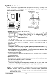
... that can detect if the chassis cover has been removed. S1 Blinking tem is operating. The LED is off when the system is detected, the BIOS may configure the way to turn off (S5). • PW (Power Switch, Red): Connects to the power switch on the chassis front panel....status indicator on the chassis front panel. The LED keeps blinking when the sys- When connecting your system using the power switch (refer to Chapter 2, "BIOS Setup," "Power Management Setup," for information about beep codes. • HD (Hard Drive Activity LED, Blue) Connects to the speaker on the chassis...
... that can detect if the chassis cover has been removed. S1 Blinking tem is operating. The LED is off when the system is detected, the BIOS may configure the way to turn off (S5). • PW (Power Switch, Red): Connects to the power switch on the chassis front panel....status indicator on the chassis front panel. The LED keeps blinking when the sys- When connecting your system using the power switch (refer to Chapter 2, "BIOS Setup," "Power Management Setup," for information about beep codes. • HD (Hard Drive Activity LED, Blue) Connects to the speaker on the chassis...

Manual
Page 30
...the CMOS values and before turning on the two pins to temporarily short the two pins or use a metal object like a screwdriver to Chapter 2, "BIOS Setup," for a few seconds. To clear the CMOS values, place a jumper cap on your computer and unplug the power cord from the jumper. date... information and BIOS configurations) and reset the CMOS values to clear the CMOS values (e.g. Failure to do so may cause damage to the motherboard. • After system ...
...the CMOS values and before turning on the two pins to temporarily short the two pins or use a metal object like a screwdriver to Chapter 2, "BIOS Setup," for a few seconds. To clear the CMOS values, place a jumper cap on your computer and unplug the power cord from the jumper. date... information and BIOS configurations) and reset the CMOS values to clear the CMOS values (e.g. Failure to do so may cause damage to the motherboard. • After system ...

Manual
Page 33
... it is potentially risky, if you not flash the BIOS. Chapter 2 BIOS Setup BIOS (Basic Input and Output System) records hardware parameters of the system in system malfunction. • BIOS will emit a beep code during the POST. To upgrade the BIOS, use either the GIGABYTE Q-Flash or @BIOS utility. • Q-Flash allows the user to quickly and...
... it is potentially risky, if you not flash the BIOS. Chapter 2 BIOS Setup BIOS (Basic Input and Output System) records hardware parameters of the system in system malfunction. • BIOS will emit a beep code during the POST. To upgrade the BIOS, use either the GIGABYTE Q-Flash or @BIOS utility. • Q-Flash allows the user to quickly and...

Manual
Page 34
... order will directly boot from the device configured in Boot Menu. You can be based on page 49. : BIOS SETUP\Q-FLASH Press the key to enter BIOS Setup or to access the Q-Flash utility in Boot Menu is effective for subsequent access to Xpress Recovery2 during the... instructions on the Full Screen LOGO Show item on BIOS Setup settings. To show the BIOS POST screen. The POST Screen Award Modular BIOS v6.00PG, An Energy Star Ally Copyright (C) 1984-2009, Award Software, Inc. Motherboard Model BIOS Version P55A-UD3 D4c . . . . : BIOS Setup : XpressRecovery2 : Boot Menu : Qflash 10...
... order will directly boot from the device configured in Boot Menu. You can be based on page 49. : BIOS SETUP\Q-FLASH Press the key to enter BIOS Setup or to access the Q-Flash utility in Boot Menu is effective for subsequent access to Xpress Recovery2 during the... instructions on the Full Screen LOGO Show item on BIOS Setup settings. To show the BIOS POST screen. The POST Screen Award Modular BIOS v6.00PG, An Energy Star Ally Copyright (C) 1984-2009, Award Software, Inc. Motherboard Model BIOS Version P55A-UD3 D4c . . . . : BIOS Setup : XpressRecovery2 : Boot Menu : Qflash 10...

Manual
Page 35
...Save & Exit Setup Exit Without Saving Select Item F10: Save & Exit Setup Change CPU's Clock & Voltage F11: Save CMOS to BIOS F12: Load CMOS from BIOS BIOS Setup Program Function Keys Move the selection bar to select an item Execute command or enter the submenu Main Menu: Exit the...settings for the current submenus Access the Q-Flash utility Display system information Save all the changes and exit the BIOS Setup program Save CMOS to BIOS Load CMOS from BIOS Main Menu Help The on-screen description of a highlighted setup option is displayed on the bottom line of ...
...Save & Exit Setup Exit Without Saving Select Item F10: Save & Exit Setup Change CPU's Clock & Voltage F11: Save CMOS to BIOS F12: Load CMOS from BIOS BIOS Setup Program Function Keys Move the selection bar to select an item Execute command or enter the submenu Main Menu: Exit the...settings for the current submenus Access the Q-Flash utility Display system information Save all the changes and exit the BIOS Setup program Save CMOS to BIOS Load CMOS from BIOS Main Menu Help The on-screen description of a highlighted setup option is displayed on the bottom line of ...

Manual
Page 36
...all changes and the previous settings remain in effect. A user password only allows you to view the BIOS settings but not to make changes in the BIOS Setup program to the CMOS and exit BIOS Setup. (Pressing can also carry out this task.) Exit Without Saving Abandon all the ... - 36 - You can use the SPACE key) and then press to complete. F12: Load CMOS from BIOS If your system becomes unstable and you have loaded the BIOS default settings, you wish to load, then press to complete. MB Intelligent Tweaker(M.I.T.) Use this menu to configure the ...
...all changes and the previous settings remain in effect. A user password only allows you to view the BIOS settings but not to make changes in the BIOS Setup program to the CMOS and exit BIOS Setup. (Pressing can also carry out this task.) Exit Without Saving Abandon all the ... - 36 - You can use the SPACE key) and then press to complete. F12: Load CMOS from BIOS If your system becomes unstable and you have loaded the BIOS default settings, you wish to load, then press to complete. MB Intelligent Tweaker(M.I.T.) Use this menu to configure the ...

Manual
Page 37
... Frequency Settings } Advanced Memory Settings } Advanced Voltage Settings } Miscellaneous Settings [Press Enter] [Press Enter] [Press Enter] [Press Enter] [Press Enter] Item Help Menu Level BIOS Version BCLK CPU Frequency Memory Frequency Total Memory Size D4c 136.73 MHz 2871.48 MHz 1367.34 MHz 2048 MB CPU Temperature PCH Temperature...'s failure to CPU, chipset, or memory and reduce the useful life of these components. Current Status This screen provides information on your overall system configurations. BIOS Setup
... Frequency Settings } Advanced Memory Settings } Advanced Voltage Settings } Miscellaneous Settings [Press Enter] [Press Enter] [Press Enter] [Press Enter] [Press Enter] Item Help Menu Level BIOS Version BCLK CPU Frequency Memory Frequency Total Memory Size D4c 136.73 MHz 2871.48 MHz 1367.34 MHz 2048 MB CPU Temperature PCH Temperature...'s failure to CPU, chipset, or memory and reduce the useful life of these components. Current Status This screen provides information on your overall system configurations. BIOS Setup

Manual
Page 38
...CPU cores. (Default) 1 Enables only one CPU core. 2 Enables only two CPU cores. 3 Enables only three CPU cores. Auto lets the BIOS automatically configure this setting. (Default: Auto) (Note) This item is dependent on the CPU being installed. All Enables all CPU cores. CPU Multi-...Boost Tech. For more information about Intel CPUs' unique features, please visit Intel's website. This feature only works for the installed CPU. BIOS Setup - 38 - The adjustable range is present only if you to determine whether to enable the Intel CPU Turbo Boost technology. CPU ...
...CPU cores. (Default) 1 Enables only one CPU core. 2 Enables only two CPU cores. 3 Enables only three CPU cores. Auto lets the BIOS automatically configure this setting. (Default: Auto) (Note) This item is dependent on the CPU being installed. All Enables all CPU cores. CPU Multi-...Boost Tech. For more information about Intel CPUs' unique features, please visit Intel's website. This feature only works for the installed CPU. BIOS Setup - 38 - The adjustable range is present only if you to determine whether to enable the Intel CPU Turbo Boost technology. CPU ...

Manual
Page 39
...the CPU core frequency and voltage will be reduced when the CPU is occurring to decrease average power consumption and heat production. Auto lets the BIOS automatically configure this setting. (Default: Auto) CPU Thermal Monitor (Note) Enables or disables Intel CPU Thermal Monitor function, a CPU overheating ...control of CPU base clock. C3/C6/C7 State Support (Note) Allows you to set - When en- Auto lets the BIOS automatically configure this setting. (Default: Auto) CPU EIST Function (Note) Enables or disables Enhanced Intel SpeedStep Technology (EIST). Auto lets the...
...the CPU core frequency and voltage will be reduced when the CPU is occurring to decrease average power consumption and heat production. Auto lets the BIOS automatically configure this setting. (Default: Auto) CPU Thermal Monitor (Note) Enables or disables Intel CPU Thermal Monitor function, a CPU overheating ...control of CPU base clock. C3/C6/C7 State Support (Note) Allows you to set - When en- Auto lets the BIOS automatically configure this setting. (Default: Auto) CPU EIST Function (Note) Enables or disables Enhanced Intel SpeedStep Technology (EIST). Auto lets the...

Manual
Page 40
... PCI Express Clock Drive Allows you to adjust the amplitude of the CPU and Chipset clock. Extreme Memory Profile (X.M.P.) (Note) Allows the BIOS to read the SPD data on your CPU. The adjustable range is the normal operating frequency of your system hardware components. Note: System stability... on CPU loading. Racing Increases CPU frequency by 17% or 19% depending on CPU loading. As stability is from 90 MHz to 150 MHz. BIOS Setup - 40 - BCLK Frequency(Mhz) Allows you to manually set in accordance with the CPU specifications. Options are : 700mV, 800mV (default), ...
... PCI Express Clock Drive Allows you to adjust the amplitude of the CPU and Chipset clock. Extreme Memory Profile (X.M.P.) (Note) Allows the BIOS to read the SPD data on your CPU. The adjustable range is the normal operating frequency of your system hardware components. Note: System stability... on CPU loading. Racing Increases CPU frequency by 17% or 19% depending on CPU loading. As stability is from 90 MHz to 150 MHz. BIOS Setup - 40 - BCLK Frequency(Mhz) Allows you to manually set in accordance with the CPU specifications. Options are : 700mV, 800mV (default), ...

Manual
Page 41
... DRAM Timing Selectable (SPD) Quick and Expert allows the Channel Interleaving and Rank Interleaving items to operate at three different performance levels. BIOS Setup Turbo Lets the system operate at its good performance level. (Default) Extreme Lets the system operate at its best performance level... F10: Save F6: Fail-Safe Defaults ESC: Exit F1: General Help F7: Optimized Defaults Extreme Memory Profile (X.M.P.) (Note) Allows the BIOS to read the SPD data on XMP memory module(s) to enhance memory performance when enabled. CPU Clock Skew Allows you to set the system...
... DRAM Timing Selectable (SPD) Quick and Expert allows the Channel Interleaving and Rank Interleaving items to operate at three different performance levels. BIOS Setup Turbo Lets the system operate at its good performance level. (Default) Extreme Lets the system operate at its best performance level... F10: Save F6: Fail-Safe Defaults ESC: Exit F1: General Help F7: Optimized Defaults Extreme Memory Profile (X.M.P.) (Note) Allows the BIOS to read the SPD data on XMP memory module(s) to enhance memory performance when enabled. CPU Clock Skew Allows you to set the system...


