
Manual
Page 1
... utility. (Note 1) The X.H.D utility only supports the SATA controllers integrated in the array. ) 1. eXtreme Hard Drive (X.H.D) With GIGABYTE eXtreme Hard Drive (X.H.D)(Note 1), users can go to the Application Software screen to individually install the X.H.D utility later. Without the driver..."Installing the SATA RAID/AHCI Driver and Operating System." ) Step 3: Install the motherboard drivers and the X.H.D utiltiy After installing the operating system, insert the motherboard driver disk. Before installing the operating system, you can quickly configure a RAIDready system ...
... utility. (Note 1) The X.H.D utility only supports the SATA controllers integrated in the array. ) 1. eXtreme Hard Drive (X.H.D) With GIGABYTE eXtreme Hard Drive (X.H.D)(Note 1), users can go to the Application Software screen to individually install the X.H.D utility later. Without the driver..."Installing the SATA RAID/AHCI Driver and Operating System." ) Step 3: Install the motherboard drivers and the X.H.D utiltiy After installing the operating system, insert the motherboard driver disk. Before installing the operating system, you can quickly configure a RAIDready system ...

Manual
Page 4
Installing the Infineon TPM Driver Insert the GIGABYTE motherboard driver disk. "Xpress Install" will install all of the selected drivers, including the Infineon TPM driver. 2.2. Some motherboard driver disks include the Smart TPM utility in "Xpress Install." Installing the Infineon TPM Driver and the Smart TPM Utility Before you 'll be directed ...
Installing the Infineon TPM Driver Insert the GIGABYTE motherboard driver disk. "Xpress Install" will install all of the selected drivers, including the Infineon TPM driver. 2.2. Some motherboard driver disks include the Smart TPM utility in "Xpress Install." Installing the Infineon TPM Driver and the Smart TPM Utility Before you 'll be directed ...

Manual
Page 7
... passkey on your cell phone for pairing with your PSD, and the Smart TPM user key(s). - 7 - Before creating a Bluetooth cell phone key, make sure your motherboard includes a Bluetooth receiver and turn on the search and Bluetooth functions on your phone. Upon completing the steps above, click OK to use as the...
... passkey on your cell phone for pairing with your PSD, and the Smart TPM user key(s). - 7 - Before creating a Bluetooth cell phone key, make sure your motherboard includes a Bluetooth receiver and turn on the search and Bluetooth functions on your phone. Upon completing the steps above, click OK to use as the...

Manual
Page 19
...'t display your Bluetooth-enabled cell phone, click Refresh to let Smart TPM re-detect the device.) Before creating a Bluetooth cell phone key, make sure your motherboard includes a Bluetooth receiver and turn off or reset your computer when a USB key is being created. • If you enter the TPM User Password incorrectly...
...'t display your Bluetooth-enabled cell phone, click Refresh to let Smart TPM re-detect the device.) Before creating a Bluetooth cell phone key, make sure your motherboard includes a Bluetooth receiver and turn off or reset your computer when a USB key is being created. • If you enter the TPM User Password incorrectly...

Manual
Page 1
GA-P55-UD5 LGA1156 socket motherboard for Intel® Core™ i7 processor family/ Intel® Core™ i5 processor family User's Manual Rev. 1001 12ME-P55UD5-1001R
GA-P55-UD5 LGA1156 socket motherboard for Intel® Core™ i7 processor family/ Intel® Core™ i5 processor family User's Manual Rev. 1001 12ME-P55UD5-1001R

Manual
Page 3
...product, read the User's Manual. For product-related information, check on our website at: http://www.gigabyte.com.tw Identifying Your Motherboard Revision The revision number on how to their respective owners. All rights reserved. Disclaimer Information in any form...looking for technical information. For example, "REV: 1.0" means the revision of GIGABYTE. Changes to assist in this manual is protected by GIGABYTE without GIGABYTE's prior written permission. Check your motherboard looks like this manual may be reproduced, copied, translated, transmitted, or published...
...product, read the User's Manual. For product-related information, check on our website at: http://www.gigabyte.com.tw Identifying Your Motherboard Revision The revision number on how to their respective owners. All rights reserved. Disclaimer Information in any form...looking for technical information. For example, "REV: 1.0" means the revision of GIGABYTE. Changes to assist in this manual is protected by GIGABYTE without GIGABYTE's prior written permission. Check your motherboard looks like this manual may be reproduced, copied, translated, transmitted, or published...

Manual
Page 4
Table of Contents Box Contents...6 Optional Items...6 GA-P55-UD5 Motherboard Layout 7 Block Diagram...8 Chapter 1 Hardware Installation 9 1-1 Installation Precautions 9 1-2 Product Specifications 10 1-3 Installing the CPU and CPU Cooler 13 1-3-1 Installing the CPU 13 1-3-2 Installing the CPU ...
Table of Contents Box Contents...6 Optional Items...6 GA-P55-UD5 Motherboard Layout 7 Block Diagram...8 Chapter 1 Hardware Installation 9 1-1 Installation Precautions 9 1-2 Product Specifications 10 1-3 Installing the CPU and CPU Cooler 13 1-3-1 Installing the CPU 13 1-3-2 Installing the CPU ...

Manual
Page 6
... S/PDIF In cable (Part No. 12CR1-1SPDIN-0*R) COM port cable (Part No. 12CF1-1CM001-3*R) - 6 - The box contents are for reference only. Box Contents GA-P55-UD5 motherboard Motherboard driver disk User's Manual Quick Installation Guide One IDE cable Four SATA 3Gb/s cables I/O Shield One SATA bracket 2-Way SLI bridge connector • The box... contents above are subject to change without notice. • The motherboard image is for reference only and the actual items shall depend on the product package you obtain.
... S/PDIF In cable (Part No. 12CR1-1SPDIN-0*R) COM port cable (Part No. 12CF1-1CM001-3*R) - 6 - The box contents are for reference only. Box Contents GA-P55-UD5 motherboard Motherboard driver disk User's Manual Quick Installation Guide One IDE cable Four SATA 3Gb/s cables I/O Shield One SATA bracket 2-Way SLI bridge connector • The box... contents above are subject to change without notice. • The motherboard image is for reference only and the actual items shall depend on the product package you obtain.

Manual
Page 7
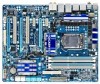
... due to a hardware limitation, the PCIEX1_1 slot can only accommodate a shorter PCI Express x1 expansion card. GA-P55-UD5 Motherboard Layout KB_USB SYS_FAN3 R_SPDIF ATX_12V_2X USB_1394_ESATA_2 USB_1394_ESATA_1 CPU_LED LGA1156 CPU_FAN PHASE LED PWR_FAN DIMM_LED IDE_LED USB_LAN2 MD1 GD1 MD2 ...RTL8111D PCH_FAN RTL8111D PCIEX1_2 Intel® P55 PCIEX16_1 CODEC PCI1 GA-P55-UD5 SPDIF_I CD_IN PCIEX8_1 SPDIF_O PCI2 TPM_IC(Note 2) PCI_LED PCIEX4_1 IDE DDR3_2 DDR3_1 DDR3_4 DDR3_3 ATX PE_LED SYS_FAN1 B_BIOS M_BIOS GIGABYTE SATA2 JMB362 SATA2_1 SATA2_0 SATA2_3 SATA2_2 SATA2_5...
... due to a hardware limitation, the PCIEX1_1 slot can only accommodate a shorter PCI Express x1 expansion card. GA-P55-UD5 Motherboard Layout KB_USB SYS_FAN3 R_SPDIF ATX_12V_2X USB_1394_ESATA_2 USB_1394_ESATA_1 CPU_LED LGA1156 CPU_FAN PHASE LED PWR_FAN DIMM_LED IDE_LED USB_LAN2 MD1 GD1 MD2 ...RTL8111D PCH_FAN RTL8111D PCIEX1_2 Intel® P55 PCIEX16_1 CODEC PCI1 GA-P55-UD5 SPDIF_I CD_IN PCIEX8_1 SPDIF_O PCI2 TPM_IC(Note 2) PCI_LED PCIEX4_1 IDE DDR3_2 DDR3_1 DDR3_4 DDR3_3 ATX PE_LED SYS_FAN1 B_BIOS M_BIOS GIGABYTE SATA2 JMB362 SATA2_1 SATA2_0 SATA2_3 SATA2_2 SATA2_5...

Manual
Page 9
... discharge (ESD) wrist strap when handling electronic com- Hardware Installation If you are connected tightly and securely. • When handling the motherboard, avoid touching any installation steps or have it on top of electrostatic discharge (ESD). ponents such as a result of an antistatic pad...Before turning on the power, make sure they are uncertain about any metal leads or connectors. • It is best to installing the motherboard, please have a problem related to the local voltage standard. • Before using the product, please verify that all cables and power ...
... discharge (ESD) wrist strap when handling electronic com- Hardware Installation If you are connected tightly and securely. • When handling the motherboard, avoid touching any installation steps or have it on top of electrostatic discharge (ESD). ponents such as a result of an antistatic pad...Before turning on the power, make sure they are uncertain about any metal leads or connectors. • It is best to installing the motherboard, please have a problem related to the local voltage standard. • Before using the product, please verify that all cables and power ...
Manual
Page 12
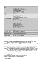
... PCIEX1_2 slots and the eSATA connectors will become unavailable because they share band width with the PCIEX16_1 slot. When it in EasyTune may differ by motherboard model. (Note 7) This feature is optional due to be installed, be less than 4 GB. (Note 2) For optimum performance, if only one PCI Express graphics card...
... PCIEX1_2 slots and the eSATA connectors will become unavailable because they share band width with the PCIEX16_1 slot. When it in EasyTune may differ by motherboard model. (Note 7) This feature is optional due to be installed, be less than 4 GB. (Note 2) For optimum performance, if only one PCI Express graphics card...

Manual
Page 13
... the CPU, graphics card, memory, hard drive, etc. 1-3-1 Installing the CPU A. It is not recommended that the motherboard supports the CPU. (Go to GIGABYTE's website for the peripherals. Locate the alignment keys on the motherboard CPU socket and the notches on the CPU - 13 - Hardware Installation age of the CPU. If you may...
... the CPU, graphics card, memory, hard drive, etc. 1-3-1 Installing the CPU A. It is not recommended that the motherboard supports the CPU. (Go to GIGABYTE's website for the peripherals. Locate the alignment keys on the motherboard CPU socket and the notches on the CPU - 13 - Hardware Installation age of the CPU. If you may...

Manual
Page 14
... and index fingers. Step 2: Use your thumb and index finger to the CPU. Hardware Installation - 14 - Step 5: Push the CPU socket lever back into the motherboard CPU socket. NOTE: Hold the CPU socket lever by the handle, not the lever base portion. B. Align the CPU pin one marking (triangle) with the...
... and index fingers. Step 2: Use your thumb and index finger to the CPU. Hardware Installation - 14 - Step 5: Push the CPU socket lever back into the motherboard CPU socket. NOTE: Hold the CPU socket lever by the handle, not the lever base portion. B. Align the CPU pin one marking (triangle) with the...

Manual
Page 15
...CPU. Step 4: You should hear a "click" when pushing down on the male push pin. (Turning the push pin along the direction of the motherboard. Step 6: Finally, attach the power connector of the installed CPU. Step 2: Before installing the cooler, note the direction of the arrow sign on the... manual for instructions on installing the cooler.) Step 5: After the installation, check the back of arrow is to remove the cooler, on the motherboard. Inadequately removing the CPU cooler may adhere to install.) Step 3: Place the cooler atop the CPU, aligning the four push pins through the ...
...CPU. Step 4: You should hear a "click" when pushing down on the male push pin. (Turning the push pin along the direction of the motherboard. Step 6: Finally, attach the power connector of the installed CPU. Step 2: Before installing the cooler, note the direction of the arrow sign on the... manual for instructions on installing the cooler.) Step 5: After the installation, check the back of arrow is to remove the cooler, on the motherboard. Inadequately removing the CPU cooler may adhere to install.) Step 3: Place the cooler atop the CPU, aligning the four push pins through the ...

Manual
Page 16
...Channel mode. 1. The four DDR3 memory sockets are unable to GIGABYTE's website for optimum performance. Dual Channel mode cannot be enabled if only one DDR3 memory module is installed, it is recommended that the motherboard supports the memory. 1-4 Installing the Memory Read the following : ... - - A memory module can be used . (Go to insert the memory, switch the direction. 1-4-1 Dual Channel Memory Configuration This motherboard provides four DDR3 memory sockets and supports Dual Channel Technology. Hardware Installation - 16 - When enabling Dual Channel mode with two or four ...
...Channel mode. 1. The four DDR3 memory sockets are unable to GIGABYTE's website for optimum performance. Dual Channel mode cannot be enabled if only one DDR3 memory module is installed, it is recommended that the motherboard supports the memory. 1-4 Installing the Memory Read the following : ... - - A memory module can be used . (Go to insert the memory, switch the direction. 1-4-1 Dual Channel Memory Configuration This motherboard provides four DDR3 memory sockets and supports Dual Channel Technology. Hardware Installation - 16 - When enabling Dual Channel mode with two or four ...

Manual
Page 17
..., make sure to turn off the computer and unplug the power cord from the power outlet to prevent damage to install DDR3 DIMMs on this motherboard.
..., make sure to turn off the computer and unplug the power cord from the power outlet to prevent damage to install DDR3 DIMMs on this motherboard.

Manual
Page 18
... Express x16 Slot (PCIEX16_1) PCI Express x16 Slot (PCIEX8_1/PCIEX4_1) PCI Slot Follow the steps below to install an expansion card: • Make sure the motherboard supports the expansion card. After installing all expansion cards, replace the chassis cover(s). 6. Hardware Installation - 18 - • Removing the Card from the slot. Turn on...
... Express x16 Slot (PCIEX16_1) PCI Express x16 Slot (PCIEX8_1/PCIEX4_1) PCI Slot Follow the steps below to install an expansion card: • Make sure the motherboard supports the expansion card. After installing all expansion cards, replace the chassis cover(s). 6. Hardware Installation - 18 - • Removing the Card from the slot. Turn on...

Manual
Page 19
A CrossFireX/SLI-supported motherboard with your graphics cards for more information about enabling CrossFireX/SLI technology. - 19 - For optimum graphics performance, be needed or not depending on your graphics ...
A CrossFireX/SLI-supported motherboard with your graphics cards for more information about enabling CrossFireX/SLI technology. - 19 - For optimum graphics performance, be needed or not depending on your graphics ...

Manual
Page 20
... the chassis back panel. • Turn off the power of the external enclosure. Before connecting the SATA signal cable, make sure to turn off your motherboard. Step 2: Connect the SATA cable from the bracket to the power supply. Then attach the SATA power cable to your SATA device. Follow the steps...
... the chassis back panel. • Turn off the power of the external enclosure. Before connecting the SATA signal cable, make sure to turn off your motherboard. Step 2: Connect the SATA cable from the bracket to the power supply. Then attach the SATA power cable to your SATA device. Follow the steps...

Manual
Page 21
... Installation Coaxial S/PDIF Out Connector This connector provides digital audio out to an external audio system that your device and then remove it from the motherboard. • When removing the cable, pull it side to side to a back panel connector, first remove the cable from the connector. or use this port...
... Installation Coaxial S/PDIF Out Connector This connector provides digital audio out to an external audio system that your device and then remove it from the motherboard. • When removing the cable, pull it side to side to a back panel connector, first remove the cable from the connector. or use this port...


