Manual
Page 6
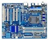
... cable (Part No. 12CF1-1FD001-7*R) 2-port USB 2.0 bracket (Part No. 12CR1-1UB030-5*R) 2-port SATA power cable (Part No. 12CF1-2SERPW-0*R) S/PDIF In cable (Part No. 12CR1-1SPDIN-0*R) COM port cable (Part No. 12CF1-1CM001-3*R) LPT port cable (Part No. 12CF1-1LP001-0*R) - 6 - Box Contents GA-P55-UD3P or GA-P55-UD3R motherboard Motherboard driver disk User's Manual...
... cable (Part No. 12CF1-1FD001-7*R) 2-port USB 2.0 bracket (Part No. 12CR1-1UB030-5*R) 2-port SATA power cable (Part No. 12CF1-2SERPW-0*R) S/PDIF In cable (Part No. 12CR1-1SPDIN-0*R) COM port cable (Part No. 12CF1-1CM001-3*R) LPT port cable (Part No. 12CF1-1LP001-0*R) - 6 - Box Contents GA-P55-UD3P or GA-P55-UD3R motherboard Motherboard driver disk User's Manual...
Manual
Page 8
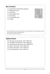
...1 PCI Express x1 2 SATA 3Gb/s ATA-133/100/66/33 IDE Channel PCI Bus GIGABYTE SATA2 DMI Interface 1 PCI Express x4 Intel® P55 x4 PCI Express Bus x1 2 SATA 3Gb/s Dual BIOS JMB362 6 SATA 3Gb/s 14 USB Ports CODEC LPC Bus IT8720 Floppy COM Port PS/2 KB/Mouse TPM j Surround Speaker Out... Center/Subwoofer Speaker Out Side Speaker Out MIC Line Out Line In S/PDIF In S/PDIF Out 4 PCI PCI CLK (33 MHz) j Only for GA-P55-UD3P. - 8 -
...1 PCI Express x1 2 SATA 3Gb/s ATA-133/100/66/33 IDE Channel PCI Bus GIGABYTE SATA2 DMI Interface 1 PCI Express x4 Intel® P55 x4 PCI Express Bus x1 2 SATA 3Gb/s Dual BIOS JMB362 6 SATA 3Gb/s 14 USB Ports CODEC LPC Bus IT8720 Floppy COM Port PS/2 KB/Mouse TPM j Surround Speaker Out... Center/Subwoofer Speaker Out Side Speaker Out MIC Line Out Line In S/PDIF In S/PDIF Out 4 PCI PCI CLK (33 MHz) j Only for GA-P55-UD3P. - 8 -
Manual
Page 11
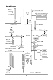
... 1 x power fan header 1 x front panel header 1 x front panel audio header 1 x CD In connector 1 x S/PDIF In header 1 x S/PDIF Out header 2 x USB 2.0/1.1 headers 1 x serial port header 1 x parallel port header 1 x clearing CMOS jumper 1 x PS/2 keyboard or PS/2 mouse port 1 x coaxial S/PDIF Out connector 1 x... optical S/PDIF Out connector 10 x USB 2.0/1.1 ports 2 x eSATA 3Gb/s ports 1 x RJ-45 port 6 x audio jacks (Center/Subwoofer Speaker Out/Rear Speaker Out/ Side Speaker Out/Line In/Line...
... 1 x power fan header 1 x front panel header 1 x front panel audio header 1 x CD In connector 1 x S/PDIF In header 1 x S/PDIF Out header 2 x USB 2.0/1.1 headers 1 x serial port header 1 x parallel port header 1 x clearing CMOS jumper 1 x PS/2 keyboard or PS/2 mouse port 1 x coaxial S/PDIF Out connector 1 x... optical S/PDIF Out connector 10 x USB 2.0/1.1 ports 2 x eSATA 3Gb/s ports 1 x RJ-45 port 6 x audio jacks (Center/Subwoofer Speaker Out/Rear Speaker Out/ Side Speaker Out/Line In/Line...
Manual
Page 19
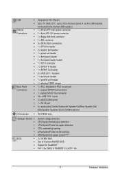
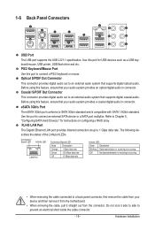
... S/PDIF Out Connector This connector provides digital audio out to Chapter 5, "Configuring SATA Hard Drive(s)," for USB devices such as a USB keyboard/mouse, USB printer, USB flash drive and etc. 1-6 Back Panel Connectors USB Port The USB port supports the USB 2.0/1.1 specification. PS/2 Keyboard/Mouse Port Use this feature, ensure that your audio system provides a coaxial digital...
... S/PDIF Out Connector This connector provides digital audio out to Chapter 5, "Configuring SATA Hard Drive(s)," for USB devices such as a USB keyboard/mouse, USB printer, USB flash drive and etc. 1-6 Back Panel Connectors USB Port The USB port supports the USB 2.0/1.1 specification. PS/2 Keyboard/Mouse Port Use this feature, ensure that your audio system provides a coaxial digital...
Manual
Page 29
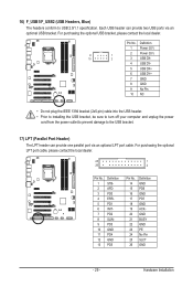
... 1 Power (5V) 9 1 2 Power (5V) 10 2 3 USB DX- 4 USB DY- 5 USB DX+ 6 USB DY+ 7 GND 8 GND 9 No Pin 10 NC • Do not plug the IEEE 1394 bracket (2x5-pin) cable into the USB header. • Prior to installing the USB bracket, be sure to turn off your computer and unplug the...the power outlet to prevent damage to USB 2.0/1.1 specification. 16) F_USB1/F_USB2 (USB Headers, Blue) The headers conform to the USB bracket. 17) LPT (Parallel Port Header) The LPT header can provide two USB ports via an optional LPT port cable. Each USB header can provide one parallel port via...
... 1 Power (5V) 9 1 2 Power (5V) 10 2 3 USB DX- 4 USB DY- 5 USB DX+ 6 USB DY+ 7 GND 8 GND 9 No Pin 10 NC • Do not plug the IEEE 1394 bracket (2x5-pin) cable into the USB header. • Prior to installing the USB bracket, be sure to turn off your computer and unplug the...the power outlet to prevent damage to USB 2.0/1.1 specification. 16) F_USB1/F_USB2 (USB Headers, Blue) The headers conform to the USB bracket. 17) LPT (Parallel Port Header) The LPT header can provide two USB ports via an optional LPT port cable. Each USB header can provide one parallel port via...
Manual
Page 36
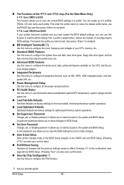
...CPU, and the primary display adapter. Integrated Peripherals Use this menu to configure all peripheral devices, such as IDE, SATA, USB, integrated audio, and integrated LAN, etc. Power Management Setup Use this menu to see information about autodetected system/CPU temperature,... are factory settings for the most stable, minimal-performance system operations. Load Optimized Defaults Optimized defaults are factory settings for GA-P55-UD3P. It allows you can also carry out this task.) Exit Without Saving Abandon all the power-saving functions. ...
...CPU, and the primary display adapter. Integrated Peripherals Use this menu to configure all peripheral devices, such as IDE, SATA, USB, integrated audio, and integrated LAN, etc. Power Management Setup Use this menu to see information about autodetected system/CPU temperature,... are factory settings for the most stable, minimal-performance system operations. Load Optimized Defaults Optimized defaults are factory settings for GA-P55-UD3P. It allows you can also carry out this task.) Exit Without Saving Abandon all the power-saving functions. ...
Manual
Page 49
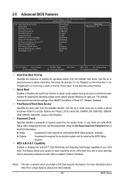
... Boot First Boot Device Second Boot Device Third Boot Device Password Check HDD S.M.A.R.T. Capability Limit CPUID Max. Options are: Floppy, LS120, Hard Disk, CDROM, ZIP, USB-FDD, USB-ZIP, USB-CDROM, USB-HDD, Legacy LAN, Disabled. HDD S.M.A.R.T.
... Boot First Boot Device Second Boot Device Third Boot Device Password Check HDD S.M.A.R.T. Capability Limit CPUID Max. Options are: Floppy, LS120, Hard Disk, CDROM, ZIP, USB-FDD, USB-ZIP, USB-CDROM, USB-HDD, Legacy LAN, Disabled. HDD S.M.A.R.T.

Manual
Page 51
... Native mode. SATA Port0-3 Native Mode (Intel P55 Chipset) Specifies the operating mode of the USB functionalities below. Disabled Allows the SATA controllers to operate in MS-DOS. (Default: Enabled) USB Storage Function Determines whether to enable advanced Serial ATA... Setup Utility-Copyright (C) 1984-2009 Award Software Integrated Peripherals SATA RAID/AHCI Mode SATA Port0-3 Native Mode USB Controllers USB Legacy Function USB Storage Function Azalia Codec Onboard H/W LAN Green LAN } SMART LAN Onboard LAN Boot ROM eSATA Controller eSATA...
... Native mode. SATA Port0-3 Native Mode (Intel P55 Chipset) Specifies the operating mode of the USB functionalities below. Disabled Allows the SATA controllers to operate in MS-DOS. (Default: Enabled) USB Storage Function Determines whether to enable advanced Serial ATA... Setup Utility-Copyright (C) 1984-2009 Award Software Integrated Peripherals SATA RAID/AHCI Mode SATA Port0-3 Native Mode USB Controllers USB Legacy Function USB Storage Function Azalia Codec Onboard H/W LAN Green LAN } SMART LAN Onboard LAN Boot ROM eSATA Controller eSATA...
Manual
Page 63
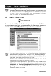
... the system. (The system will continue to restart your system. After the system restart, "Xpress Install" will then autodetect and install the USB 2.0 driver.) - 63 - Or click Install Single Items to manually select the drivers you wish to My Computer, double-click the optical drive... Drivers After inserting the driver disk, "Xpress Install" will install all the drivers that shown in the motherboard driver disk. • For USB 2.0 driver support under the Windows XP operating system, please install the Windows XP Service Pack 1 or later. You can click the Install All...
... the system. (The system will continue to restart your system. After the system restart, "Xpress Install" will then autodetect and install the USB 2.0 driver.) - 63 - Or click Install Single Items to manually select the drivers you wish to My Computer, double-click the optical drive... Drivers After inserting the driver disk, "Xpress Install" will install all the drivers that shown in the motherboard driver disk. • For USB 2.0 driver support under the Windows XP operating system, please install the Windows XP Service Pack 1 or later. You can click the Install All...
Manual
Page 67
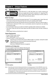
... data and perform restoration of system memory • VESA compatible graphics card • Windows XP with Xpress Recovery cannot be restored using Xpress Recovery2. • USB hard drives are different utilities. Step 2: Click New. (Note) Xpress Recovery2 checks the first physical hard drive in RAID/AHCI mode are attached to leave...
... data and perform restoration of system memory • VESA compatible graphics card • Windows XP with Xpress Recovery cannot be restored using Xpress Recovery2. • USB hard drives are different utilities. Step 2: Click New. (Note) Xpress Recovery2 checks the first physical hard drive in RAID/AHCI mode are attached to leave...
Manual
Page 70
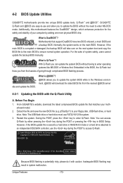
4-2 BIOS Update Utilities GIGABYTE motherboards provide two unique BIOS update tools, Q-Flash™ and @BIOS™. Motherboards that matches your floppy disk, USB flash drive, or hard drive. For the sake of going through complicated BIOS flashing process. Embedded in the BIOS, the Q-... file is @BIOS™? @BIOS allows you can access Q-Flash by adding one more physical BIOS chip. P55-UD3P D6 . . . . : BIOS Setup : XpressRecovery2 : Boot Menu : Qflash 07/08/2009-P55-7A89RG0JC-00 Because BIOS flashing is DualBIOS™? What is potentially risky, please do it with the Q-Flash...
4-2 BIOS Update Utilities GIGABYTE motherboards provide two unique BIOS update tools, Q-Flash™ and @BIOS™. Motherboards that matches your floppy disk, USB flash drive, or hard drive. For the sake of going through complicated BIOS flashing process. Embedded in the BIOS, the Q-... file is @BIOS™? @BIOS allows you can access Q-Flash by adding one more physical BIOS chip. P55-UD3P D6 . . . . : BIOS Setup : XpressRecovery2 : Boot Menu : Qflash 07/08/2009-P55-7A89RG0JC-00 Because BIOS flashing is DualBIOS™? What is potentially risky, please do it with the Q-Flash...
Manual
Page 71
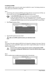
... press . Update BIOS from Drive Save BIOS to access Q-Flash. 2. The following procedure assumes that you save the current BIOS file. • Q-Flash only supports USB flash drive or hard drives using FAT32/16/12 file system. • If the BIOS update file is saved. In the main menu of the... process. • Do not turn off or restart the system when the system is reading/updating the BIOS. • Do not remove the floppy disk, USB flash drive, or hard drive when the system is displayed on the screen. Step 3: When the update process is complete, press any key to return...
... press . Update BIOS from Drive Save BIOS to access Q-Flash. 2. The following procedure assumes that you save the current BIOS file. • Q-Flash only supports USB flash drive or hard drives using FAT32/16/12 file system. • If the BIOS update file is saved. In the main menu of the... process. • Do not turn off or restart the system when the system is reading/updating the BIOS. • Do not remove the floppy disk, USB flash drive, or hard drive when the system is displayed on the screen. Step 3: When the update process is complete, press any key to return...
Manual
Page 81
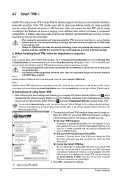
... initialize the TPM chip, set up your computer. • Previously encrypted files will appear in the notification area. GIGABYTE is configured as the Smart TPM user key. Instructions for GA-P55-UD3P. - 81 - Set Your TPM Password A password is cleared. Be sure to memorize this setting) to ... sure to be saved. After configuring the above settings and restarting your computer, the Infineon Security Platform icon , which your Bluetooth cell phone/USB flash drive as a result of the password(s) or the key(s) will be cracked or read. • Though the TPM delivers the latest...
... initialize the TPM chip, set up your computer. • Previously encrypted files will appear in the notification area. GIGABYTE is configured as the Smart TPM user key. Instructions for GA-P55-UD3P. - 81 - Set Your TPM Password A password is cleared. Be sure to memorize this setting) to ... sure to be saved. After configuring the above settings and restarting your computer, the Infineon Security Platform icon , which your Bluetooth cell phone/USB flash drive as a result of the password(s) or the key(s) will be cracked or read. • Though the TPM delivers the latest...
Manual
Page 84
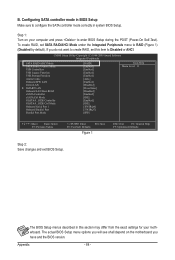
... see shall depend on your motherboard. CMOS Setup Utility-Copyright (C) 1984-2009 Award Software Integrated Peripherals SATA RAID/AHCI Mode SATA Port0-3 Native Mode USB Controllers USB Legacy Function USB Storage Function Azalia Codec Onboard H/W LAN Green LAN } SMART LAN Onboard LAN Boot ROM eSATA Controller eSATA Ctrl Mode GSATA 0_1/IDE Controller...
... see shall depend on your motherboard. CMOS Setup Utility-Copyright (C) 1984-2009 Award Software Integrated Peripherals SATA RAID/AHCI Mode SATA Port0-3 Native Mode USB Controllers USB Legacy Function USB Storage Function Azalia Codec Onboard H/W LAN Green LAN } SMART LAN Onboard LAN Boot ROM eSATA Controller eSATA Ctrl Mode GSATA 0_1/IDE Controller...
Manual
Page 91
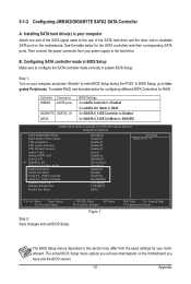
...IDE CMOS Setup Utility-Copyright (C) 1984-2009 Award Software Integrated Peripherals SATA RAID/AHCI Mode SATA Port0-3 Native Mode USB Controllers USB Legacy Function USB Storage Function Azalia Codec Onboard H/W LAN Green LAN } SMART LAN Onboard LAN Boot ROM eSATA Controller eSATA Ctrl Mode...to the hard drive. Then connect the power connector from the exact settings for RAID. Controller Connectors JMB362 eSATA ports GIGABYTE GSATA2_0/1 SATA2 BIOS Settings Set eSATA Controller to Enabled Set eSATA Ctrl Mode to RAID Set GSATA 0_1/IDE Controller to...
...IDE CMOS Setup Utility-Copyright (C) 1984-2009 Award Software Integrated Peripherals SATA RAID/AHCI Mode SATA Port0-3 Native Mode USB Controllers USB Legacy Function USB Storage Function Azalia Codec Onboard H/W LAN Green LAN } SMART LAN Onboard LAN Boot ROM eSATA Controller eSATA Ctrl Mode...to the hard drive. Then connect the power connector from the exact settings for RAID. Controller Connectors JMB362 eSATA ports GIGABYTE GSATA2_0/1 SATA2 BIOS Settings Set eSATA Controller to Enabled Set eSATA Ctrl Mode to RAID Set GSATA 0_1/IDE Controller to...
Manual
Page 97
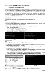
...floppy disk and the motherboard driver disk (here we as- Press after the command: • For the Intel P55, type (Figure 1): (Note) A:\>copy d:\bootdrv\imsm\32bit\*.* • For the JMB362/GIGABYTE SATA2, type (Figure 2): (Note) A:\>copy d:\bootdrv\gsata\32bit\*.* Figure 1 In Windows mode: Figure 2 ... mode, you need to install the SATA controller driver during the Windows setup process. See the instructions below about how to a USB flash drive. For installing Windows Vista, you wish to the floppy disk. 5-1-3 Making a SATA RAID/AHCI Driver Diskette (Required ...
...floppy disk and the motherboard driver disk (here we as- Press after the command: • For the Intel P55, type (Figure 1): (Note) A:\>copy d:\bootdrv\imsm\32bit\*.* • For the JMB362/GIGABYTE SATA2, type (Figure 2): (Note) A:\>copy d:\bootdrv\gsata\32bit\*.* Figure 1 In Windows mode: Figure 2 ... mode, you need to install the SATA controller driver during the Windows setup process. See the instructions below about how to a USB flash drive. For installing Windows Vista, you wish to the floppy disk. 5-1-3 Making a SATA RAID/AHCI Driver Diskette (Required ...
Manual
Page 100
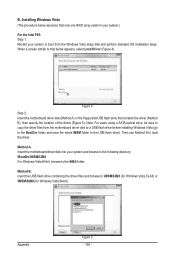
... drive containing the driver files and browse to the USB flash drive). When a screen similar to that only one RAID array exists in your system.) For the Intel P55: Step 1: Restart your system and browse to the following directory: \BootDrv\iMSM\32Bit For Windows Vista 64-bit, browse to ...load the driver. Method A: Insert the motherboard driver disk into your system to boot from the motherboard driver disk to a USB flash drive before installing...
... drive containing the driver files and browse to the USB flash drive). When a screen similar to that only one RAID array exists in your system.) For the Intel P55: Step 1: Restart your system and browse to the following directory: \BootDrv\iMSM\32Bit For Windows Vista 64-bit, browse to ...load the driver. Method A: Insert the motherboard driver disk into your system to boot from the motherboard driver disk to a USB flash drive before installing...
Manual
Page 102
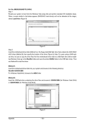
...SATA RAID/ AHCI driver (Method B), then specify the location of the driver (Figure 9). Then use Method B to the 64Bit folder. For the JMB362/GIGABYTE SATA2: Step 1: Restart your system and browse to the following directory: \BootDrv\GSATA\32Bit For Windows Vista 64-bit, browse to load the driver. ...before installing Windows Vista (go to the BootDrv folder and save the whole GSATA folder to the USB flash drive). Figure 8 Step 2: Insert the motherboard driver disk (Method A) or the floppy disk/USB flash drive that below appears (RAID/AHCI hard drive(s) will not be sure to copy the ...
...SATA RAID/ AHCI driver (Method B), then specify the location of the driver (Figure 9). Then use Method B to the 64Bit folder. For the JMB362/GIGABYTE SATA2: Step 1: Restart your system and browse to the following directory: \BootDrv\GSATA\32Bit For Windows Vista 64-bit, browse to load the driver. ...before installing Windows Vista (go to the BootDrv folder and save the whole GSATA folder to the USB flash drive). Figure 8 Step 2: Insert the motherboard driver disk (Method A) or the floppy disk/USB flash drive that below appears (RAID/AHCI hard drive(s) will not be sure to copy the ...


