Manual
Page 1
GA-P55-UD3P GA-P55-UD3R LGA1156 socket motherboard for Intel® Core™ i7 processor family/ Intel® Core™ i5 processor family User's Manual Rev. 1001 12ME-P55UD3P-1001R
GA-P55-UD3P GA-P55-UD3R LGA1156 socket motherboard for Intel® Core™ i7 processor family/ Intel® Core™ i5 processor family User's Manual Rev. 1001 12ME-P55UD3P-1001R
Manual
Page 4
Table of Contents Box Contents...6 Optional Items...6 GA-P55-UD3P/GA-P55-UD3R Motherboard Layout 7 Block Diagram...8 Chapter 1 Hardware Installation 9 1-1 Installation Precautions 9 1-2 Product Specifications 10 1-3 Installing the CPU and CPU Cooler 13 1-3-1 Installing the CPU 13 1-3-2 Installing the ...
Table of Contents Box Contents...6 Optional Items...6 GA-P55-UD3P/GA-P55-UD3R Motherboard Layout 7 Block Diagram...8 Chapter 1 Hardware Installation 9 1-1 Installation Precautions 9 1-2 Product Specifications 10 1-3 Installing the CPU and CPU Cooler 13 1-3-1 Installing the CPU 13 1-3-2 Installing the ...
Manual
Page 5
...2 75 4-5 Q-Share...77 4-6 Smart 6™ ...78 4-7 Smart TPM j 81 Chapter 5 Appendix...83 5-1 Configuring SATA Hard Drive(s 83 5-1-1 Configuring Intel P55 SATA Controllers 83 5-1-2 Configuring JMB362/GIGABYTE SATA2 SATA Controller 91 5-1-3 Making a SATA RAID/AHCI Driver Diskette 97 5-1-4 Installing the SATA RAID/AHCI Driver and Operating System 98 5-2 Configuring Audio...Microphone Recording 113 5-2-4 Using the Sound Recorder 115 5-3 Troubleshooting 116 5-3-1 Frequently Asked Questions 116 5-3-2 Troubleshooting Procedure 117 5-4 Regulatory Statements 119 j Only for GA-P55-UD3P. - 5 -
...2 75 4-5 Q-Share...77 4-6 Smart 6™ ...78 4-7 Smart TPM j 81 Chapter 5 Appendix...83 5-1 Configuring SATA Hard Drive(s 83 5-1-1 Configuring Intel P55 SATA Controllers 83 5-1-2 Configuring JMB362/GIGABYTE SATA2 SATA Controller 91 5-1-3 Making a SATA RAID/AHCI Driver Diskette 97 5-1-4 Installing the SATA RAID/AHCI Driver and Operating System 98 5-2 Configuring Audio...Microphone Recording 113 5-2-4 Using the Sound Recorder 115 5-3 Troubleshooting 116 5-3-1 Frequently Asked Questions 116 5-3-2 Troubleshooting Procedure 117 5-4 Regulatory Statements 119 j Only for GA-P55-UD3P. - 5 -
Manual
Page 6
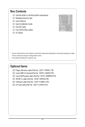
...-1SPDIN-0*R) COM port cable (Part No. 12CF1-1CM001-3*R) LPT port cable (Part No. 12CF1-1LP001-0*R) - 6 - The box contents are for reference only. Box Contents GA-P55-UD3P or GA-P55-UD3R motherboard Motherboard driver disk User's Manual Quick Installation Guide One IDE cable Four SATA 3Gb/s cables I/O Shield • The box contents above are subject...
...-1SPDIN-0*R) COM port cable (Part No. 12CF1-1CM001-3*R) LPT port cable (Part No. 12CF1-1LP001-0*R) - 6 - The box contents are for reference only. Box Contents GA-P55-UD3P or GA-P55-UD3R motherboard Motherboard driver disk User's Manual Quick Installation Guide One IDE cable Four SATA 3Gb/s cables I/O Shield • The box contents above are subject...
Manual
Page 7
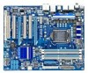
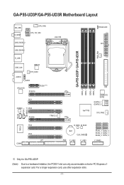
..., use other expansion slots. - 7 - GA-P55-UD3P/GA-P55-UD3R Motherboard Layout KB_USB R_SPDIF CPU_FAN ATX_12V_2X4 USB_ESATA_2 USB_ESATA_1 LGA1156 PHASE LED ATX PWR_FAN GA-P55-UD3P / GA-P55-UD3R R_USB USB_LAN JMB362 SYS_FAN1 AUDIO F_AUDIO RTL8111D PCIEX16 PCIEX1(Note) PCI1 CODEC PCI2 PCIEX4 TPM IC j DDR3_2 DDR3_1 IDE DDR3_4 DDR3_3 GIGABYTE SATA2 GSATA2_1 GSATA2_0 Intel® P55 SYS_FAN2 CD_IN SPDIF_I SPDIF_O IT8720...
..., use other expansion slots. - 7 - GA-P55-UD3P/GA-P55-UD3R Motherboard Layout KB_USB R_SPDIF CPU_FAN ATX_12V_2X4 USB_ESATA_2 USB_ESATA_1 LGA1156 PHASE LED ATX PWR_FAN GA-P55-UD3P / GA-P55-UD3R R_USB USB_LAN JMB362 SYS_FAN1 AUDIO F_AUDIO RTL8111D PCIEX16 PCIEX1(Note) PCI1 CODEC PCI2 PCIEX4 TPM IC j DDR3_2 DDR3_1 IDE DDR3_4 DDR3_3 GIGABYTE SATA2 GSATA2_1 GSATA2_0 Intel® P55 SYS_FAN2 CD_IN SPDIF_I SPDIF_O IT8720...
Manual
Page 8
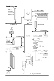
... Bus x1 PCIe CLK (100 MHz) x1 1 PCI Express x1 2 SATA 3Gb/s ATA-133/100/66/33 IDE Channel PCI Bus GIGABYTE SATA2 DMI Interface 1 PCI Express x4 Intel® P55 x4 PCI Express Bus x1 2 SATA 3Gb/s Dual BIOS JMB362 6 SATA 3Gb/s 14 USB Ports CODEC LPC Bus IT8720 Floppy COM... Speaker Out Center/Subwoofer Speaker Out Side Speaker Out MIC Line Out Line In S/PDIF In S/PDIF Out 4 PCI PCI CLK (33 MHz) j Only for GA-P55-UD3P. - 8 -
... Bus x1 PCIe CLK (100 MHz) x1 1 PCI Express x1 2 SATA 3Gb/s ATA-133/100/66/33 IDE Channel PCI Bus GIGABYTE SATA2 DMI Interface 1 PCI Express x4 Intel® P55 x4 PCI Express Bus x1 2 SATA 3Gb/s Dual BIOS JMB362 6 SATA 3Gb/s 14 USB Ports CODEC LPC Bus IT8720 Floppy COM... Speaker Out Center/Subwoofer Speaker Out Side Speaker Out MIC Line Out Line In S/PDIF In S/PDIF Out 4 PCI PCI CLK (33 MHz) j Only for GA-P55-UD3P. - 8 -
Manual
Page 10
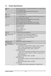
.../Intel® Core™ i5 series processor in the LGA1156 package (Go to GIGABYTE's website for the latest CPU support list.) L3 cache varies with CPU Chipset Intel® P55 Express Chipset Memory Audio 4 x 1.5V DDR3 DIMM sockets supporting up to...800 MHz memory modules Support for non-ECC memory modules Support for Extreme Memory Profile (XMP) memory modules (Go to GIGABYTE's website for the latest memory support list.) Realtek ALC888 codec High Definition Audio 2/4/5.1/7.1-channel Support for ...
.../Intel® Core™ i5 series processor in the LGA1156 package (Go to GIGABYTE's website for the latest CPU support list.) L3 cache varies with CPU Chipset Intel® P55 Express Chipset Memory Audio 4 x 1.5V DDR3 DIMM sockets supporting up to...800 MHz memory modules Support for non-ECC memory modules Support for Extreme Memory Profile (XMP) memory modules (Go to GIGABYTE's website for the latest memory support list.) Realtek ALC888 codec High Definition Audio 2/4/5.1/7.1-channel Support for ...
Manual
Page 12
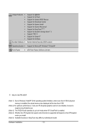
... Internet Security (OEM version) Operating System w Support for Microsoft® Windows® 7/Vista/XP Form Factor w ATX Form Factor; 30.5cm x 24.4cm j Only for GA-P55-UD3P. (Note 1) Due to Windows Vista/XP 32-bit operating system limitation, when more than 4 GB of physical memory is installed, the actual memory size...
... Internet Security (OEM version) Operating System w Support for Microsoft® Windows® 7/Vista/XP Form Factor w ATX Form Factor; 30.5cm x 24.4cm j Only for GA-P55-UD3P. (Note 1) Due to Windows Vista/XP 32-bit operating system limitation, when more than 4 GB of physical memory is installed, the actual memory size...
Manual
Page 24
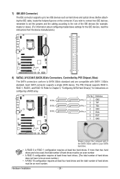
Each SATA connector supports a single SATA device. The P55 Chipset supports RAID 0, RAID 1, RAID 5, and RAID 10. Refer to be used, the total number of hard drives must be an even number.) • A RAID ... information about configuring master/slave settings for the IDE devices, read the instructions from the device manufacturers.) 40 39 2 1 8) SATA2_0/1/2/3/4/5 (SATA 3Gb/s Connectors, Controlled by P55 Chipset, Blue) The SATA connectors conform to SATA 3Gb/s standard and are to Chapter 5, "Configuring SATA Hard Drive(s)," for instructions on the connector.
Each SATA connector supports a single SATA device. The P55 Chipset supports RAID 0, RAID 1, RAID 5, and RAID 10. Refer to be used, the total number of hard drives must be an even number.) • A RAID ... information about configuring master/slave settings for the IDE devices, read the instructions from the device manufacturers.) 40 39 2 1 8) SATA2_0/1/2/3/4/5 (SATA 3Gb/s Connectors, Controlled by P55 Chipset, Blue) The SATA connectors conform to SATA 3Gb/s standard and are to Chapter 5, "Configuring SATA Hard Drive(s)," for instructions on the connector.

Manual
Page 34
... Setup first. A. The LOGO Screen (Default) B. To show the BIOS POST screen. BIOS Setup - 34 - Motherboard Model BIOS Version P55-UD3P D6 . . . . : BIOS Setup : XpressRecovery2 : Boot Menu : Qflash 07/08/2009-P55-7A89RG0JC-00 Function Keys Function Keys Function Keys: : POST SCREEN Press the key to show the BIOS POST screen at...
... Setup first. A. The LOGO Screen (Default) B. To show the BIOS POST screen. BIOS Setup - 34 - Motherboard Model BIOS Version P55-UD3P D6 . . . . : BIOS Setup : XpressRecovery2 : Boot Menu : Qflash 07/08/2009-P55-7A89RG0JC-00 Function Keys Function Keys Function Keys: : POST SCREEN Press the key to show the BIOS POST screen at...
Manual
Page 35
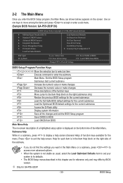
... for the current submenus Load the Optimized BIOS default settings for each item is displayed on the bottom line of function keys available for GA-P55-UD3P. - 35 - Use arrow keys to move among the items and press to accept or enter a sub-menu. (Sample BIOS Version...: GA-P55-UD3P D6) CMOS Setup Utility-Copyright (C) 1984-2009 Award Software MB Intelligent Tweaker(M.I.T.) Standard CMOS Features Advanced BIOS Features Integrated Peripherals...
... for the current submenus Load the Optimized BIOS default settings for each item is displayed on the bottom line of function keys available for GA-P55-UD3P. - 35 - Use arrow keys to move among the items and press to accept or enter a sub-menu. (Sample BIOS Version...: GA-P55-UD3P D6) CMOS Setup Utility-Copyright (C) 1984-2009 Award Software MB Intelligent Tweaker(M.I.T.) Standard CMOS Features Advanced BIOS Features Integrated Peripherals...
Manual
Page 36
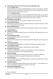
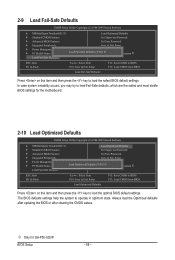
... Defaults Fail-Safe defaults are factory settings for the most stable, minimal-performance system operations. Load Optimized Defaults Optimized defaults are factory settings for GA-P55-UD3P. BIOS Setup - 36 - You can use the SPACE key) and then press to complete. F12: Load CMOS from a profile created before, without the...
... Defaults Fail-Safe defaults are factory settings for the most stable, minimal-performance system operations. Load Optimized Defaults Optimized defaults are factory settings for GA-P55-UD3P. BIOS Setup - 36 - You can use the SPACE key) and then press to complete. F12: Load CMOS from a profile created before, without the...

Manual
Page 51
...Defaults ESC: Exit F1: General Help F7: Optimized Defaults SATA RAID/AHCI Mode (Intel P55 Chipset) Enables or disables RAID for the SATA controllers. SATA Port0-3 Native Mode (Intel P55 Chipset) Specifies the operating mode of the USB functionalities below. Enable Native IDE mode ...do not support Native mode. (Default) Enabled Allows the SATA controllers to install operating systems that cannot be used in the Intel P55 chipset or configures the SATA controllers to AHCI mode. USB Controllers Enables or disables the integrated USB 1.0 controller. (Default: Enabled)...
...Defaults ESC: Exit F1: General Help F7: Optimized Defaults SATA RAID/AHCI Mode (Intel P55 Chipset) Enables or disables RAID for the SATA controllers. SATA Port0-3 Native Mode (Intel P55 Chipset) Specifies the operating mode of the USB functionalities below. Enable Native IDE mode ...do not support Native mode. (Default) Enabled Allows the SATA controllers to install operating systems that cannot be used in the Intel P55 chipset or configures the SATA controllers to AHCI mode. USB Controllers Enables or disables the integrated USB 1.0 controller. (Default: Enabled)...
Manual
Page 58
... optimum state. In case system instability occurs, you may try to load Fail-Safe defaults, which are the safest and most stable BIOS settings for GA-P55-UD3P. 2-9 Load Fail-Safe Defaults CMOS Setup Utility-Copyright (C) 1984-2009 Award Software MB Intelligent Tweaker(M.I .T.) Load Optimized Defaults Standard CMOS Features Set...
... optimum state. In case system instability occurs, you may try to load Fail-Safe defaults, which are the safest and most stable BIOS settings for GA-P55-UD3P. 2-9 Load Fail-Safe Defaults CMOS Setup Utility-Copyright (C) 1984-2009 Award Software MB Intelligent Tweaker(M.I .T.) Load Optimized Defaults Standard CMOS Features Set...
Manual
Page 59
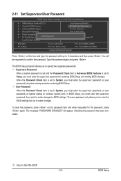
... Password When the Password Check item is set to make changes. The message "PASSWORD DISABLED" will be requested to 8 characters and then press . j Only for GA-P55-UD3P. - 59 - In BIOS Setup, you must enter the supervisor password if you to view the BIOS settings but not to make changes to Setup...
... Password When the Password Check item is set to make changes. The message "PASSWORD DISABLED" will be requested to 8 characters and then press . j Only for GA-P55-UD3P. - 59 - In BIOS Setup, you must enter the supervisor password if you to view the BIOS settings but not to make changes to Setup...
Manual
Page 60
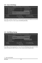
BIOS Setup - 60 - j Only for GA-P55-UD3P. Press or to return to BIOS F12: Load CMOS from BIOS Press on this item and press the key. 2-12 Save & Exit Setup CMOS ...
BIOS Setup - 60 - j Only for GA-P55-UD3P. Press or to return to BIOS F12: Load CMOS from BIOS Press on this item and press the key. 2-12 Save & Exit Setup CMOS ...
Manual
Page 61
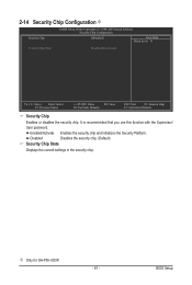
j Only for GA-P55-UD3P. - 61 - BIOS Setup Enabled/Activate Enables the security chip and initializes the Security Platform. Disabled Disables the security chip. (Default) Security Chip State Displays ...
j Only for GA-P55-UD3P. - 61 - BIOS Setup Enabled/Activate Enables the security chip and initializes the Security Platform. Disabled Disables the security chip. (Default) Security Chip State Displays ...
Manual
Page 70
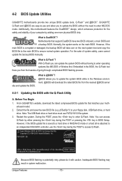
...16/12 file system. 3. 4-2 BIOS Update Utilities GIGABYTE motherboards provide two unique BIOS update tools, Q-Flash™ and @BIOS™. P55-UD3P D6 . . . . : BIOS Setup : XpressRecovery2 : Boot Menu : Qflash 07/08/2009-P55-7A89RG0JC-00 Because BIOS flashing is corrupted or damaged..., the backup BIOS will download the latest BIOS file from the hassles of going through complicated BIOS flashing process. From GIGABYTE's website, download the latest compressed BIOS update ...
...16/12 file system. 3. 4-2 BIOS Update Utilities GIGABYTE motherboards provide two unique BIOS update tools, Q-Flash™ and @BIOS™. P55-UD3P D6 . . . . : BIOS Setup : XpressRecovery2 : Boot Menu : Qflash 07/08/2009-P55-7A89RG0JC-00 Because BIOS flashing is corrupted or damaged..., the backup BIOS will download the latest BIOS file from the hassles of going through complicated BIOS flashing process. From GIGABYTE's website, download the latest compressed BIOS update ...
Manual
Page 81
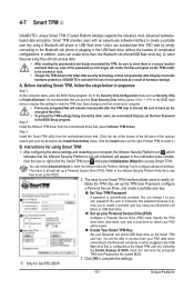
... key using your own password. You will be directed to your Bluetooth cell phone or USB flash drive. Unique Features 4-7 Smart TPM j GIGABYTE's unique Smart TPM (Trusted Platform Module) supports the industry's most advanced hardwarebased data encryption. You can select Advanced mode to enter the Infineon... an easy-to the Bluetooth cell phone or plugging in sequence: Step 1: As the computer starts, enter the BIOS Setup program. Instructions for GA-P55-UD3P. - 81 - Set up the encrypted files first. • To prevent the TPM settings being cleared by simply connecting to -use...
... key using your own password. You will be directed to your Bluetooth cell phone or USB flash drive. Unique Features 4-7 Smart TPM j GIGABYTE's unique Smart TPM (Trusted Platform Module) supports the industry's most advanced hardwarebased data encryption. You can select Advanced mode to enter the Infineon... an easy-to the Bluetooth cell phone or plugging in sequence: Step 1: As the computer starts, enter the BIOS Setup program. Instructions for GA-P55-UD3P. - 81 - Set up the encrypted files first. • To prevent the TPM settings being cleared by simply connecting to -use...
Manual
Page 83
..., on your computer Attach one hard drive. • An empty formatted floppy disk. • Windows Vista/XP setup disk. • Motherboard driver disk. 5-1-1 Configuring Intel P55 SATA Controllers A. If you do not want to create RAID array. (Note 2) Required when the SATA controller is set to create RAID, you may prepare... ensure optimal performance, it is more than one SATA controller on this motherboard, the SATA2_0, SATA2_1, SATA2_2, SATA2_3, SATA2_4 and SATA2_5 ports are supported by P55 Chipset.) Then connect the power connector from your computer.
..., on your computer Attach one hard drive. • An empty formatted floppy disk. • Windows Vista/XP setup disk. • Motherboard driver disk. 5-1-1 Configuring Intel P55 SATA Controllers A. If you do not want to create RAID array. (Note 2) Required when the SATA controller is set to create RAID, you may prepare... ensure optimal performance, it is more than one SATA controller on this motherboard, the SATA2_0, SATA2_1, SATA2_2, SATA2_3, SATA2_4 and SATA2_5 ports are supported by P55 Chipset.) Then connect the power connector from your computer.