Manual
Page 1
GA-P43T-ES3G LGA775 socket motherboard for Intel® Core™ processor family/ Intel® Pentium® processor family/Intel® Celeron® processor family User's Manual Rev. 1301 12ME-P43TE3G-1301R
GA-P43T-ES3G LGA775 socket motherboard for Intel® Core™ processor family/ Intel® Pentium® processor family/Intel® Celeron® processor family User's Manual Rev. 1301 12ME-P43TE3G-1301R

Manual
Page 2
Motherboard GA-P43T-ES3G Nov. 18, 2009 Motherboard GA-P43T-ES3G Nov. 18, 2009
Motherboard GA-P43T-ES3G Nov. 18, 2009 Motherboard GA-P43T-ES3G Nov. 18, 2009

Manual
Page 3
... features, read the User's Manual. For product-related information, check on our website at: http://www.gigabyte.com Identifying Your Motherboard Revision The revision number on our website. For example, "REV: 1.0" means the revision of the motherboard is the property of this manual may be reproduced, copied, translated, transmitted, or published in any...
... features, read the User's Manual. For product-related information, check on our website at: http://www.gigabyte.com Identifying Your Motherboard Revision The revision number on our website. For example, "REV: 1.0" means the revision of the motherboard is the property of this manual may be reproduced, copied, translated, transmitted, or published in any...

Manual
Page 4
Table of Contents Box Contents...6 Optional Items...6 GA-P43T-ES3G Motherboard Layout 7 GA-P43T-ES3G Motherboard Block Diagram 8 Chapter 1 Hardware Installation 9 1-1 Installation Precautions 9 1-2 Product Specifications 10 1-3 Installing the CPU and CPU Cooler 13 1-3-1 Installing the CPU 13 1-3-2 Installing the CPU Cooler ...
Table of Contents Box Contents...6 Optional Items...6 GA-P43T-ES3G Motherboard Layout 7 GA-P43T-ES3G Motherboard Block Diagram 8 Chapter 1 Hardware Installation 9 1-1 Installation Precautions 9 1-2 Product Specifications 10 1-3 Installing the CPU and CPU Cooler 13 1-3-1 Installing the CPU 13 1-3-2 Installing the CPU Cooler ...

Manual
Page 6
Box Contents GA-P43T-ES3G motherboard Motherboard driver disk User's Manual Quick Installation Guide One IDE cable Two SATA cables I/O Shield • The box contents above are subject to change without notice. • The motherboard image is for reference only and the actual items shall depend on the product package you obtain. The box contents are for reference only. Optional Items Floppy disk drive cable (Part No. 12CF1-1FD001-7*R) 2-port USB 2.0 bracket (Part No. 12CR1-1UB030-5*R) 2-port SATA power cable (Part No. 12CF1-2SERPW-0*R) - 6 -
Box Contents GA-P43T-ES3G motherboard Motherboard driver disk User's Manual Quick Installation Guide One IDE cable Two SATA cables I/O Shield • The box contents above are subject to change without notice. • The motherboard image is for reference only and the actual items shall depend on the product package you obtain. The box contents are for reference only. Optional Items Floppy disk drive cable (Part No. 12CF1-1FD001-7*R) 2-port USB 2.0 bracket (Part No. 12CR1-1UB030-5*R) 2-port SATA power cable (Part No. 12CF1-2SERPW-0*R) - 6 -

Manual
Page 7
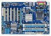
GA-P43T-ES3G Motherboard Layout KB_MS ATX_12V LGA775 CPU_FAN ATX COMA LPT DDR3_1 DDR3_2 DDR3_3 DDR3_4 COAXIAL R_USB USB_LAN SYS_FAN1 AUDIO Intel® P43 F_AUDIO PCIEX1 Realtek RTL8111D PCIEX16 PCI1 GA-P43T-ES3G IDE JMicron JMB368 PCI2 CODEC PCI3 SPDIF_O PCI4 iTE IT8718 PCI5 CD_IN FDD Intel® ICH10 SYS_FAN2 M_BIOS BAT B_BIOS CLR_CMOS SATA2_3 SATA2_0 SATA2_4 SATA2_1 SATA2_5 SATA2_2 CI F_USB3 F_USB2 F_USB1 F_PANEL PWR_LED - 7 -
GA-P43T-ES3G Motherboard Layout KB_MS ATX_12V LGA775 CPU_FAN ATX COMA LPT DDR3_1 DDR3_2 DDR3_3 DDR3_4 COAXIAL R_USB USB_LAN SYS_FAN1 AUDIO Intel® P43 F_AUDIO PCIEX1 Realtek RTL8111D PCIEX16 PCI1 GA-P43T-ES3G IDE JMicron JMB368 PCI2 CODEC PCI3 SPDIF_O PCI4 iTE IT8718 PCI5 CD_IN FDD Intel® ICH10 SYS_FAN2 M_BIOS BAT B_BIOS CLR_CMOS SATA2_3 SATA2_0 SATA2_4 SATA2_1 SATA2_5 SATA2_2 CI F_USB3 F_USB2 F_USB1 F_PANEL PWR_LED - 7 -

Manual
Page 8
GA-P43T-ES3G Motherboard Block Diagram PCIe CLK (100 MHz) LGA775 CPU CPU CLK+/(400(O.C.)/333/266 MHz Host Interface DDR3 1600/1333/1066 MHz PCI Express x16 Intel&#...
GA-P43T-ES3G Motherboard Block Diagram PCIe CLK (100 MHz) LGA775 CPU CPU CLK+/(400(O.C.)/333/266 MHz Host Interface DDR3 1600/1333/1066 MHz PCI Express x16 Intel&#...

Manual
Page 9
... not have an ESD wrist strap, keep your hands dry and first touch a metal object to eliminate static electricity. • Prior to installing the motherboard, please have a problem related to the use of the product, please consult a certified computer technician. - 9 - Prior to installation, carefully read the...high-temperature environment. • Turning on top of your dealer. If you are connected tightly and securely. • When handling the motherboard, avoid touching any installation steps or have it on the computer power during the installation process can become damaged as...
... not have an ESD wrist strap, keep your hands dry and first touch a metal object to eliminate static electricity. • Prior to installing the motherboard, please have a problem related to the use of the product, please consult a certified computer technician. - 9 - Prior to installation, carefully read the...high-temperature environment. • Turning on top of your dealer. If you are connected tightly and securely. • When handling the motherboard, avoid touching any installation steps or have it on the computer power during the installation process can become damaged as...

Manual
Page 12
... 3) Whether the CPU fan speed control function is supported will depend on the CPU cooler you install. (Note 4) Available functions in EasyTune may differ by motherboard model. (Note 5) Due to the hardware limitation, you must install the Intel® Core™ 2 Extreme/ Core™ 2 Quad/ Core™ 2 Duo/ Pentium Dual-Core...
... 3) Whether the CPU fan speed control function is supported will depend on the CPU cooler you install. (Note 4) Available functions in EasyTune may differ by motherboard model. (Note 5) Due to the hardware limitation, you must install the Intel® Core™ 2 Extreme/ Core™ 2 Quad/ Core™ 2 Duo/ Pentium Dual-Core...

Manual
Page 13
... installing the CPU to your hardware specifications including the CPU, graphics card, memory, hard drive, etc. 1-3-1 Installing the CPU A. Locate the alignment keys on the motherboard CPU socket and the notches on the CPU - 13 - It is not installed, otherwise overheating and dam- LGA775 CPU Socket Alignment Key LGA775 CPU Alignment... is not recommended that the system bus frequency be inserted if oriented incorrectly. (Or you begin to install the CPU: • Make sure that the motherboard supports the CPU. (Go to GIGABYTE's website for the peripherals.
... installing the CPU to your hardware specifications including the CPU, graphics card, memory, hard drive, etc. 1-3-1 Installing the CPU A. Locate the alignment keys on the motherboard CPU socket and the notches on the CPU - 13 - It is not installed, otherwise overheating and dam- LGA775 CPU Socket Alignment Key LGA775 CPU Alignment... is not recommended that the system bus frequency be inserted if oriented incorrectly. (Or you begin to install the CPU: • Make sure that the motherboard supports the CPU. (Go to GIGABYTE's website for the peripherals.

Manual
Page 14
... Installation - 14 - Step 5: Once the CPU is not installed.) Step 4: Hold the CPU with the socket alignment keys) and gently insert the CPU into the motherboard CPU socket. Before installing the CPU, make sure to turn off the computer and unplug the power cord from the load plate. (To protect the...
... Installation - 14 - Step 5: Once the CPU is not installed.) Step 4: Hold the CPU with the socket alignment keys) and gently insert the CPU into the motherboard CPU socket. Before installing the CPU, make sure to turn off the computer and unplug the power cord from the load plate. (To protect the...

Manual
Page 15
... 5: After the installation, check the back of the CPU cooler to the CPU fan header (CPU_FAN) on the motherboard. Step 6: Finally, attach the power connector of the motherboard. Hardware Installation Direction of the Arrow Sign on the Male Push Pin Male Push Pin The Top of Female Push ...push pins diagonally. Push down each push pin. 1-3-2 Installing the CPU Cooler Follow the steps below to correctly install the CPU cooler on the motherboard. (The following procedure uses Intel® boxed cooler as the picture above shows, the installation is to install.) Step 3: Place the cooler ...
... 5: After the installation, check the back of the CPU cooler to the CPU fan header (CPU_FAN) on the motherboard. Step 6: Finally, attach the power connector of the motherboard. Hardware Installation Direction of the Arrow Sign on the Male Push Pin Male Push Pin The Top of Female Push ...push pins diagonally. Push down each push pin. 1-3-2 Installing the CPU Cooler Follow the steps below to correctly install the CPU cooler on the motherboard. (The following procedure uses Intel® boxed cooler as the picture above shows, the installation is to install.) Step 3: Place the cooler ...
Manual
Page 16
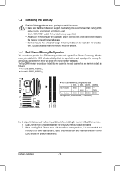
... one DDR3 memory module is recommended that memory of the same capacity, brand, speed, and chips be used . (Go to GIGABYTE's website for optimum performance. Enabling Dual Channel memory mode will automatically detect the specifications and capacity of the same capacity, brand, speed...; Memory modules have a foolproof design. If you begin to insert the memory, switch the direction. 1-4-1 Dual Channel Memory Configuration This motherboard provides four DDR3 memory sockets and supports Dual Channel Technology. The four DDR3 memory sockets are unable to install the memory: • ...
... one DDR3 memory module is recommended that memory of the same capacity, brand, speed, and chips be used . (Go to GIGABYTE's website for optimum performance. Enabling Dual Channel memory mode will automatically detect the specifications and capacity of the same capacity, brand, speed...; Memory modules have a foolproof design. If you begin to insert the memory, switch the direction. 1-4-1 Dual Channel Memory Configuration This motherboard provides four DDR3 memory sockets and supports Dual Channel Technology. The four DDR3 memory sockets are unable to install the memory: • ...
Manual
Page 17
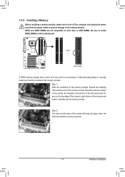
..., make sure to turn off the computer and unplug the power cord from the power outlet to prevent damage to install DDR3 DIMMs on this motherboard. Notch DDR3 DIMM A DDR3 memory module has a notch, so it vertically into place when the memory module is securely inserted. - 17 - DDR3 and DDR2 DIMMs...
..., make sure to turn off the computer and unplug the power cord from the power outlet to prevent damage to install DDR3 DIMMs on this motherboard. Notch DDR3 DIMM A DDR3 memory module has a notch, so it vertically into place when the memory module is securely inserted. - 17 - DDR3 and DDR2 DIMMs...

Manual
Page 18
... turn off the computer and unplug the power cord from the power outlet before you begin to install an expansion card: • Make sure the motherboard supports the expansion card. If necessary, go to BIOS Setup to make any required BIOS changes for your operating system. Remove the metal slot cover...
... turn off the computer and unplug the power cord from the power outlet before you begin to install an expansion card: • Make sure the motherboard supports the expansion card. If necessary, go to BIOS Setup to make any required BIOS changes for your operating system. Remove the metal slot cover...

Manual
Page 19
... a coaxial digital audio in a 4/5.1-channel audio configuration. To enable 7.1-channel audio, you have to connect a PS/2 keyboard. Do not rock it straight out from the motherboard. • When removing the cable, pull it side to side to this audio jack for line in jack. scribes the states of the LAN port...
... a coaxial digital audio in a 4/5.1-channel audio configuration. To enable 7.1-channel audio, you have to connect a PS/2 keyboard. Do not rock it straight out from the motherboard. • When removing the cable, pull it side to side to this audio jack for line in jack. scribes the states of the LAN port...

Manual
Page 20
... devices and your devices are compliant with the connectors you wish to connect. • Before installing the devices, be sure to the connector on the motherboard. 1-7 Internal Connectors 1 3 2 4 6 11 16 13 4 7 10 12 5 15 14 9 8 1) ATX_12V 2) ATX 3) CPU_FAN 4) SYS_FAN1/SYS_FAN2 5) FDD 6) IDE 7) SATA2_0/1/2/3/4/5 8) PWR_LED 9) BAT 10) F_PANEL 11) F_AUDIO 12) CD_IN...
... devices and your devices are compliant with the connectors you wish to connect. • Before installing the devices, be sure to the connector on the motherboard. 1-7 Internal Connectors 1 3 2 4 6 11 16 13 4 7 10 12 5 15 14 9 8 1) ATX_12V 2) ATX 3) CPU_FAN 4) SYS_FAN1/SYS_FAN2 5) FDD 6) IDE 7) SATA2_0/1/2/3/4/5 8) PWR_LED 9) BAT 10) F_PANEL 11) F_AUDIO 12) CD_IN...

Manual
Page 21
... for 2x12-pin ATX) GND (Only for 2x12-pin ATX) - 21 - To meet expansion requirements, it is turned off and all the components on the motherboard. If the 12V power connector is used that can withstand high power consumption be used (500W or greater). Hardware Installation Before connecting the power connector...
... for 2x12-pin ATX) GND (Only for 2x12-pin ATX) - 21 - To meet expansion requirements, it is turned off and all the components on the motherboard. If the 12V power connector is used that can withstand high power consumption be used (500W or greater). Hardware Installation Before connecting the power connector...

Manual
Page 22
... a stripe of the connector and the floppy disk drive cable. 3/4) CPU_FAN/SYS_FAN1/SYS_FAN2 (Fan Headers) The motherboard has a 4-pin CPU fan header (CPU_FAN) and a 4-pin (SYS_FAN2) and a 3-pin (SYS_ FAN1) system fan headers. The motherboard supports CPU fan speed control, which requires the use of floppy disk drives supported are not configuration...
... a stripe of the connector and the floppy disk drive cable. 3/4) CPU_FAN/SYS_FAN1/SYS_FAN2 (Fan Headers) The motherboard has a 4-pin CPU fan header (CPU_FAN) and a 4-pin (SYS_FAN2) and a 3-pin (SYS_ FAN1) system fan headers. The motherboard supports CPU fan speed control, which requires the use of floppy disk drives supported are not configuration...

Manual
Page 26
... Audio." • Audio signals will make the device unable to this header. Incorrect connection between the module connector and the motherboard header will be present on each wire instead of the motherboard header. If your chassis front panel audio module to work or even damage it. 11) F_AUDIO (Front Panel Audio Header...
... Audio." • Audio signals will make the device unable to this header. Incorrect connection between the module connector and the motherboard header will be present on each wire instead of the motherboard header. If your chassis front panel audio module to work or even damage it. 11) F_AUDIO (Front Panel Audio Header...


