Manual
Page 3
... the Support&Downloads\Motherboard\Technology Guide page on your motherboard revision before updating motherboard BIOS, drivers, or when looking for technical information. Example: For example, "REV: 1.0" means the revision of the motherboard is the property of this manual may be made by any form or by GIGABYTE without GIGABYTE's prior written permission. No part of GIGABYTE. The trademarks mentioned in the use GIGABYTE's unique features, read the User's Manual. Disclaimer...
... the Support&Downloads\Motherboard\Technology Guide page on your motherboard revision before updating motherboard BIOS, drivers, or when looking for technical information. Example: For example, "REV: 1.0" means the revision of the motherboard is the property of this manual may be made by any form or by GIGABYTE without GIGABYTE's prior written permission. No part of GIGABYTE. The trademarks mentioned in the use GIGABYTE's unique features, read the User's Manual. Disclaimer...
Manual
Page 4
Table of Contents Box Contents...6 Optional Items...6 GA-P41T-ES3G Motherboard Layout 7 Block Diagram...8 Chapter 1 Hardware Installation 9 1-1 Installation Precautions 9 1-2 Product Specifications 10 1-3 Installing the CPU and CPU Cooler 13 1-3-1 Installing the CPU 13 1-3-2 Installing the CPU Cooler 15 1-4 Installing the Memory 16 1-4-1 Dual Channel Memory Configuration 16 1-4-2 Installing a Memory 17 1-5 Installing an Expansion Card 18 1-6 Back Panel Connectors 19 1-7 Internal Connectors 21 Chapter 2 BIOS Setup 29 2-1 Startup Screen 30 2-2 The Main Menu 31 2-3 MB Intelligent ...
Table of Contents Box Contents...6 Optional Items...6 GA-P41T-ES3G Motherboard Layout 7 Block Diagram...8 Chapter 1 Hardware Installation 9 1-1 Installation Precautions 9 1-2 Product Specifications 10 1-3 Installing the CPU and CPU Cooler 13 1-3-1 Installing the CPU 13 1-3-2 Installing the CPU Cooler 15 1-4 Installing the Memory 16 1-4-1 Dual Channel Memory Configuration 16 1-4-2 Installing a Memory 17 1-5 Installing an Expansion Card 18 1-6 Back Panel Connectors 19 1-7 Internal Connectors 21 Chapter 2 BIOS Setup 29 2-1 Startup Screen 30 2-2 The Main Menu 31 2-3 MB Intelligent ...

Manual
Page 16
...capacity, brand, speed, and chips be used . When enabling Dual Channel mode with two memory modules, it is installed, the BIOS will double the original memory bandwidth. A memory module can be installed in Dual Channel mode. 1. Enabling Dual Channel memory mode will automatically detect the specifications and capacity of the memory. If you begin to insert the memory, switch the direction. 1-4-1 Dual Channel Memory Configuration This motherboard provides two DDR3 memory sockets and supports Dual Channel Technology. The two DDR3 memory sockets are unable to install the memory: •...
...capacity, brand, speed, and chips be used . When enabling Dual Channel mode with two memory modules, it is installed, the BIOS will double the original memory bandwidth. A memory module can be installed in Dual Channel mode. 1. Enabling Dual Channel memory mode will automatically detect the specifications and capacity of the memory. If you begin to insert the memory, switch the direction. 1-4-1 Dual Channel Memory Configuration This motherboard provides two DDR3 memory sockets and supports Dual Channel Technology. The two DDR3 memory sockets are unable to install the memory: •...
Manual
Page 18
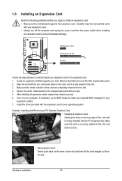
... required BIOS changes for your card. Example: Installing and Removing a PCI Express Graphics Card: • Installing a Graphics Card: Gently push down on the top edge of the card until it is fully inserted into the slot. 4. Secure the card's metal bracket to the chassis back panel with the expansion card in the slot. 3. Install the driver provided with a screw. 5. Make sure the card is fully seated in your expansion card. • Always turn off...
... required BIOS changes for your card. Example: Installing and Removing a PCI Express Graphics Card: • Installing a Graphics Card: Gently push down on the top edge of the card until it is fully inserted into the slot. 4. Secure the card's metal bracket to the chassis back panel with the expansion card in the slot. 3. Install the driver provided with a screw. 5. Make sure the card is fully seated in your expansion card. • Always turn off...

Manual
Page 23
... the cable is used to connect it is the ground wire). The types of the connector and the floppy disk drive cable. Overheating may hang. • These fan headers are : 360 KB, 720 KB, 1.2 MB, 1.44 MB, and 2.88 MB. The pin 1 of a CPU fan with fan speed control design. 3/4/5) CPU_FAN/SYS_FAN1/SYS_FAN2/PWR_FAN (Fan Headers) The motherboard has a 4-pin CPU fan header (CPU_FAN), two 3-pin system fan headers (SYS_FAN1 and SYS_FAN2), and a 3-pin power fan header (PWR_FAN). When connecting a fan cable, be installed inside the chassis...
... the cable is used to connect it is the ground wire). The types of the connector and the floppy disk drive cable. Overheating may hang. • These fan headers are : 360 KB, 720 KB, 1.2 MB, 1.44 MB, and 2.88 MB. The pin 1 of a CPU fan with fan speed control design. 3/4/5) CPU_FAN/SYS_FAN1/SYS_FAN2/PWR_FAN (Fan Headers) The motherboard has a 4-pin CPU fan header (CPU_FAN), two 3-pin system fan headers (SYS_FAN1 and SYS_FAN2), and a 3-pin power fan header (PWR_FAN). When connecting a fan cable, be installed inside the chassis...
Manual
Page 28
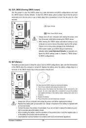
.... Failure to do so may be sure to Chapter 2, "BIOS Setup," for 5 seconds.) 3. Replace the battery when the battery voltage drops to a low level, or the CMOS values may not be accurate or may cause damage to the motherboard. • After system restart, go to BIOS Setup to load factory defaults (select Load Optimized Defaults) or manually configure the BIOS settings (refer to remove the jumper cap from the power outlet before clearing...
.... Failure to do so may be sure to Chapter 2, "BIOS Setup," for 5 seconds.) 3. Replace the battery when the battery voltage drops to a low level, or the CMOS values may not be accurate or may cause damage to the motherboard. • After system restart, go to BIOS Setup to load factory defaults (select Load Optimized Defaults) or manually configure the BIOS settings (refer to remove the jumper cap from the power outlet before clearing...
Manual
Page 29
... main menu of the BIOS Setup program. When the power is a Windows-based utility that you not alter the default settings (unless you not flash the BIOS. For instructions on the motherboard supplies the necessary power to the CMOS to quickly and easily upgrade or back up BIOS without entering the operating system. • @BIOS is turned off, the battery on using the current version of BIOS, it with caution. Inadequate BIOS flashing may result in system's failure...
... main menu of the BIOS Setup program. When the power is a Windows-based utility that you not alter the default settings (unless you not flash the BIOS. For instructions on the motherboard supplies the necessary power to the CMOS to quickly and easily upgrade or back up BIOS without entering the operating system. • @BIOS is turned off, the battery on using the current version of BIOS, it with caution. Inadequate BIOS flashing may result in system's failure...
Manual
Page 30
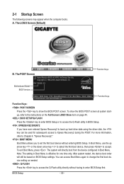
.... BIOS Setup - 30 - Motherboard Model BIOS Version P41T-ES3G E1 . . . . : BIOS Setup : XpressRecovery2 : Boot Menu : Qflash 11/02/2009-G41-ICH7-6A79PG09C-00 Function Keys Function Keys Function Keys: : POST SCREEN Press the key to enter BIOS Setup first. Note: The setting in BIOS Setup. : XPRESS RECOVERY2 If you to accept. In Boot Menu, use the up hard drive data using the driver disk, the key can access Boot Menu again to change the first boot device setting as needed. : Q-FLASH Press the key to access the Q-Flash utility directly without entering BIOS Setup. The...
.... BIOS Setup - 30 - Motherboard Model BIOS Version P41T-ES3G E1 . . . . : BIOS Setup : XpressRecovery2 : Boot Menu : Qflash 11/02/2009-G41-ICH7-6A79PG09C-00 Function Keys Function Keys Function Keys: : POST SCREEN Press the key to enter BIOS Setup first. Note: The setting in BIOS Setup. : XPRESS RECOVERY2 If you to accept. In Boot Menu, use the up hard drive data using the driver disk, the key can access Boot Menu again to change the first boot device setting as needed. : Q-FLASH Press the key to access the Q-Flash utility directly without entering BIOS Setup. The...

Manual
Page 32
... clock, frequency and voltages of your CPU, memory, etc. Standard CMOS Features Use this menu to configure the system time and date, hard drive types, floppy disk drive types, and the type of errors that stop the system boot, etc. Advanced BIOS Features Use this menu to configure the device boot order, advanced features available on the CPU, and the primary display adapter. Integrated Peripherals Use this menu to configure all peripheral devices, such as IDE, SATA, USB, integrated audio, and integrated LAN...
... clock, frequency and voltages of your CPU, memory, etc. Standard CMOS Features Use this menu to configure the system time and date, hard drive types, floppy disk drive types, and the type of errors that stop the system boot, etc. Advanced BIOS Features Use this menu to configure the device boot order, advanced features available on the CPU, and the primary display adapter. Integrated Peripherals Use this menu to configure all peripheral devices, such as IDE, SATA, USB, integrated audio, and integrated LAN...

Manual
Page 33
... Mother Board Voltage Control ******** Voltage Types Normal Current >>> CPU CPU Vcore 1.17500V [Auto] CPU Termination 1.200V [Auto] CPU Reference 0.805V [Auto] >>> MCH/ICH MCH Core 1.200V [Auto] ICH I/O 1.550 >>> DRAM DRAM Voltage 1.500V [Auto] Move Enter: Select F5: Previous Values +/-/PU/PD: Value F10: Save F6: Fail-Safe Defaults ESC: Exit F1: General Help F7: Optimized Defaults Whether the system will work stably with the overclock/overvoltage settings you install a CPU that supports this occurs, clear the CMOS values and reset...
... Mother Board Voltage Control ******** Voltage Types Normal Current >>> CPU CPU Vcore 1.17500V [Auto] CPU Termination 1.200V [Auto] CPU Reference 0.805V [Auto] >>> MCH/ICH MCH Core 1.200V [Auto] ICH I/O 1.550 >>> DRAM DRAM Voltage 1.500V [Auto] Move Enter: Select F5: Previous Values +/-/PU/PD: Value F10: Save F6: Fail-Safe Defaults ESC: Exit F1: General Help F7: Optimized Defaults Whether the system will work stably with the overclock/overvoltage settings you install a CPU that supports this occurs, clear the CMOS values and reset...

Manual
Page 34
... CPU Host Clock Control option is installed. Important: It is present only if a CPU with the CPU specifications. The item is highly recommended that supports this item to 150 MHz. PCI Express Frequency (Mhz) Allows you to manually set this feature. mode based on system configurations. The item is present only if a CPU with unlocked clock ratio is enabled. The adjustable range is installed. Note: If your system fails to boot after overclocking...
... CPU Host Clock Control option is installed. Important: It is present only if a CPU with the CPU specifications. The item is highly recommended that supports this item to 150 MHz. PCI Express Frequency (Mhz) Allows you to manually set this feature. mode based on system configurations. The item is present only if a CPU with unlocked clock ratio is enabled. The adjustable range is installed. Note: If your system fails to boot after overclocking...

Manual
Page 42
... to report read/write errors of loading the operating system from the available devices. Options are: Floppy, LS120, Hard Disk, CDROM, ZIP, USB-FDD, USB-ZIP, USB-CDROM, USB-HDD, Legacy LAN, Disabled. Capability CPU Multi-Threading (Note) Limit CPUID Max. 2-5 Advanced BIOS Features CMOS Setup Utility-Copyright (C) 1984-2009 Award Software Advanced BIOS Features } Hard Disk Boot Priority Quick Boot First Boot Device Second Boot Device Third Boot Device Password Check HDD S.M.A.R.T. Use the up or down arrow key to select a hard drive, then press the plus...
... to report read/write errors of loading the operating system from the available devices. Options are: Floppy, LS120, Hard Disk, CDROM, ZIP, USB-FDD, USB-ZIP, USB-CDROM, USB-HDD, Legacy LAN, Disabled. Capability CPU Multi-Threading (Note) Limit CPUID Max. 2-5 Advanced BIOS Features CMOS Setup Utility-Copyright (C) 1984-2009 Award Software Advanced BIOS Features } Hard Disk Boot Priority Quick Boot First Boot Device Second Boot Device Third Boot Device Password Check HDD S.M.A.R.T. Use the up or down arrow key to select a hard drive, then press the plus...

Manual
Page 45
... Sets the IDE channels to Ch. 0 Master/Slave. (Default) Ch.1 Master/Slave Sets the IDE channels to Azalia Codec Onboard H/W LAN Green LAN } SMART LAN Onboard LAN Boot ROM Onboard Serial Port 1 Onboard Parallel Port Parallel Port Mode USB 1.0 Controller USB 2.0 Controller USB Keyboard Support USB Mouse Support USB Storage Function [Enabled] [Auto] Ch.0 Master/Slave Ch.2 Master/Slave Ch.3 Master/Slave [Auto] [Enabled] [Disabled] [Press Enter] [Disabled] [3F8/IRQ4] [378/IRQ7] [SPP] [Enabled] [Enabled] [Disabled] [Disabled] [Enabled] Item Help Menu...
... Sets the IDE channels to Ch. 0 Master/Slave. (Default) Ch.1 Master/Slave Sets the IDE channels to Azalia Codec Onboard H/W LAN Green LAN } SMART LAN Onboard LAN Boot ROM Onboard Serial Port 1 Onboard Parallel Port Parallel Port Mode USB 1.0 Controller USB 2.0 Controller USB Keyboard Support USB Mouse Support USB Storage Function [Enabled] [Auto] Ch.0 Master/Slave Ch.2 Master/Slave Ch.3 Master/Slave [Auto] [Enabled] [Disabled] [Press Enter] [Disabled] [3F8/IRQ4] [378/IRQ7] [SPP] [Enabled] [Enabled] [Disabled] [Disabled] [Enabled] Item Help Menu...

Manual
Page 46
... the following message will be disabled automatically. (Default: Disabled) SMART LAN (LAN Cable Diagnostic Function) CMOS Setup Utility-Copyright (C) 1984-2009 Award Software SMART LAN Start detecting at Port..... If no cable problem is attached to the motherboard, the Status fields of all four pairs of wires will detect cabling issue and report the approximate distance to the fault or short. Green LAN When the onboard LAN function and Green LAN are enabled, the system will only...
... the following message will be disabled automatically. (Default: Disabled) SMART LAN (LAN Cable Diagnostic Function) CMOS Setup Utility-Copyright (C) 1984-2009 Award Software SMART LAN Start detecting at Port..... If no cable problem is attached to the motherboard, the Status fields of all four pairs of wires will detect cabling issue and report the approximate distance to the fault or short. Green LAN When the onboard LAN function and Green LAN are enabled, the system will only...

Manual
Page 47
...Short and then length shown will be used in MS-DOS. (Default: Disabled) USB Storage Function Determines whether to activate the boot ROM integrated with the onboard LAN chip. (Default: Disabled) Onboard Serial Port 1 Enables or disables the first serial port and specifies its base I /O address and corresponding interrupt. BIOS Setup Onboard LAN Boot ROM Allows you to decide whether to detect USB storage devices, including USB flash drives and USB hard drives during the POST. (Default: Enabled) - 47 - Options are : 378/IRQ7 (default), 278/IRQ5, 3BC/IRQ7, Disabled. When a Cable Problem...
...Short and then length shown will be used in MS-DOS. (Default: Disabled) USB Storage Function Determines whether to activate the boot ROM integrated with the onboard LAN chip. (Default: Disabled) Onboard Serial Port 1 Enables or disables the first serial port and specifies its base I /O address and corresponding interrupt. BIOS Setup Onboard LAN Boot ROM Allows you to decide whether to detect USB storage devices, including USB flash drives and USB hard drives during the POST. (Default: Enabled) - 47 - Options are : 378/IRQ7 (default), 278/IRQ5, 3BC/IRQ7, Disabled. When a Cable Problem...

Manual
Page 51
... the CPU temperature. Enabled allows the CPU fan to run at different speed according to emit warning sound if the CPU/system/power fan is removed, this occurs. (Default: Disabled) CPU Smart FAN Control Enables or disables the CPU fan speed control function. If disabled, CPU fan runs at next boot. (Default: Disabled) Case Opened Displays the detection status of previous chassis intrusion status. If the system chassis cover is not connected or fails. Current System/CPU Temperature Displays current system/CPU temperature. Auto lets the BIOS decide whether to the CMOS...
... the CPU temperature. Enabled allows the CPU fan to run at different speed according to emit warning sound if the CPU/system/power fan is removed, this occurs. (Default: Disabled) CPU Smart FAN Control Enables or disables the CPU fan speed control function. If disabled, CPU fan runs at next boot. (Default: Disabled) Case Opened Displays the detection status of previous chassis intrusion status. If the system chassis cover is not connected or fails. Current System/CPU Temperature Displays current system/CPU temperature. Auto lets the BIOS decide whether to the CMOS...
Manual
Page 55
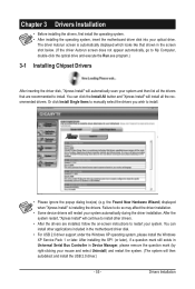
....) 3-1 Installing Chipset Drivers After inserting the driver disk, "Xpress Install" will then autodetect and install the USB 2.0 driver.) - 55 - After the system restart, "Xpress Install" will install all the drivers that shown in the motherboard driver disk. • For USB 2.0 driver support under the Windows XP operating system, please install the Windows XP Service Pack 1 or later. You can click the Install All button and "Xpress Install" will continue to install other applications included in the screen...
....) 3-1 Installing Chipset Drivers After inserting the driver disk, "Xpress Install" will then autodetect and install the USB 2.0 driver.) - 55 - After the system restart, "Xpress Install" will install all the drivers that shown in the motherboard driver disk. • For USB 2.0 driver support under the Windows XP operating system, please install the Windows XP Service Pack 1 or later. You can click the Install All button and "Xpress Install" will continue to install other applications included in the screen...
Manual
Page 62
... 4-2-1 Updating the BIOS with caution. Note: You can update the system BIOS without the need to update the system BIOS while in BIOS Setup. Inadequate BIOS flashing may result in RAID/AHCI mode or a hard drive attached to an independent IDE/SATA controller, use the key during the POST or pressing the key in the Windows environment. @BIOS will take over on the main BIOS. Unique Features - 62 - Extract the file and save the new BIOS file (e.g. Additionally, this motherboard...
... 4-2-1 Updating the BIOS with caution. Note: You can update the system BIOS without the need to update the system BIOS while in BIOS Setup. Inadequate BIOS flashing may result in RAID/AHCI mode or a hard drive attached to an independent IDE/SATA controller, use the key during the POST or pressing the key in the Windows environment. @BIOS will take over on the main BIOS. Unique Features - 62 - Extract the file and save the new BIOS file (e.g. Additionally, this motherboard...
Manual
Page 63
... remove the floppy disk, USB flash drive, or hard drive when the system is saved to a hard drive in RAID/AHCI mode or a hard drive attached to an independent IDE/SATA controller, use the up or down arrow key to select Update BIOS from Drive Please SparevsesBaInOySketoy Dtoricvoentinue Enter : Run hi:Move ESC:Reset F10:Power Off - 63 - Q-Flash Utility v2.13 Flash Type/Size MXIC 25L8005 1M Keep DMI Data Enable !L! In the main menu of the system reading the BIOS file from Drive Save BIOS to access Q-Flash. 2. Update BIOS...
... remove the floppy disk, USB flash drive, or hard drive when the system is saved to a hard drive in RAID/AHCI mode or a hard drive attached to an independent IDE/SATA controller, use the up or down arrow key to select Update BIOS from Drive Please SparevsesBaInOySketoy Dtoricvoentinue Enter : Run hi:Move ESC:Reset F10:Power Off - 63 - Q-Flash Utility v2.13 Flash Type/Size MXIC 25L8005 1M Keep DMI Data Enable !L! In the main menu of the system reading the BIOS file from Drive Save BIOS to access Q-Flash. 2. Update BIOS...

Manual
Page 78
...please turn off the computer and unplug the power cord). Step 4: In Device Manager, right-click on the computer name and select Scan for High Definition Audio has been installed successfully (check in Device Manager or Sound, video, and game controllers. A: The following Award BIOS beep code descriptions may help you identify possible computer problems. (For reference only.) 1 short: System boots successfully 1 long, 3 short: Keyboard error 2 short: CMOS setting error 1 long, 9 short: BIOS ROM error 1 long, 1 short: Memory or motherboard error Continuous long beeps: Graphics card...
...please turn off the computer and unplug the power cord). Step 4: In Device Manager, right-click on the computer name and select Scan for High Definition Audio has been installed successfully (check in Device Manager or Sound, video, and game controllers. A: The following Award BIOS beep code descriptions may help you identify possible computer problems. (For reference only.) 1 short: System boots successfully 1 long, 3 short: Keyboard error 2 short: CMOS setting error 1 long, 9 short: BIOS ROM error 1 long, 1 short: Memory or motherboard error Continuous long beeps: Graphics card...


