Manual
Page 1
GA-P41-ES3G LGA775 socket motherboard for Intel® Core™ processor family/ Intel® Pentium® processor family/Intel® Celeron® processor family User's Manual Rev. 1001 12ME-P41ES3G-1001R
GA-P41-ES3G LGA775 socket motherboard for Intel® Core™ processor family/ Intel® Pentium® processor family/Intel® Celeron® processor family User's Manual Rev. 1001 12ME-P41ES3G-1001R
Manual
Page 2
Motherboard GA-P41-ES3G Sept. 21, 2009 Motherboard GA-P41-ES3G Sept. 21, 2009
Motherboard GA-P41-ES3G Sept. 21, 2009 Motherboard GA-P41-ES3G Sept. 21, 2009
Manual
Page 3
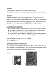
... reserved. For example, "REV: 1.0" means the revision of GIGABYTE. Disclaimer Information in this manual may be made by copyright laws and is the property of the motherboard is protected by GIGABYTE without GIGABYTE's prior written permission. For product-related information, check on our... website at: http://www.gigabyte.com.tw Identifying Your Motherboard Revision The revision number on how to their ...
... reserved. For example, "REV: 1.0" means the revision of GIGABYTE. Disclaimer Information in this manual may be made by copyright laws and is the property of the motherboard is protected by GIGABYTE without GIGABYTE's prior written permission. For product-related information, check on our... website at: http://www.gigabyte.com.tw Identifying Your Motherboard Revision The revision number on how to their ...
Manual
Page 4
Table of Contents Box Contents...6 Optional Items...6 GA-P41-ES3G Motherboard Layout 7 Block Diagram...8 Chapter 1 Hardware Installation 9 1-1 Installation Precautions 9 1-2 Product Specifications 10 1-3 Installing the CPU and CPU Cooler 13 1-3-1 Installing the CPU 13 1-3-2 Installing the CPU ...
Table of Contents Box Contents...6 Optional Items...6 GA-P41-ES3G Motherboard Layout 7 Block Diagram...8 Chapter 1 Hardware Installation 9 1-1 Installation Precautions 9 1-2 Product Specifications 10 1-3 Installing the CPU and CPU Cooler 13 1-3-1 Installing the CPU 13 1-3-2 Installing the CPU ...
Manual
Page 6
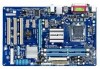
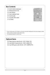
The box contents are for reference only. Optional Items Floppy disk drive cable (Part No. 12CF1-1FD001-7*R) 2-port USB 2.0 bracket (Part No. 12CR1-1UB030-5*R) 2-port SATA power cable (Part No. 12CF1-2SERPW-0*R) - 6 - Box Contents GA-P41-ES3G motherboard Motherboard driver disk User's Manual Quick Installation Guide One IDE cable Two SATA 3Gb/s cables I/O Shield • The box contents above are subject to change without notice. • The motherboard image is for reference only and the actual items shall depend on the product package you obtain.
The box contents are for reference only. Optional Items Floppy disk drive cable (Part No. 12CF1-1FD001-7*R) 2-port USB 2.0 bracket (Part No. 12CR1-1UB030-5*R) 2-port SATA power cable (Part No. 12CF1-2SERPW-0*R) - 6 - Box Contents GA-P41-ES3G motherboard Motherboard driver disk User's Manual Quick Installation Guide One IDE cable Two SATA 3Gb/s cables I/O Shield • The box contents above are subject to change without notice. • The motherboard image is for reference only and the actual items shall depend on the product package you obtain.
Manual
Page 9
...sure the power supply has been turned off. • Before turning on the computer power during the installation process can become damaged as a motherboard, CPU or memory. These stickers are required for warranty validation. • Always remove the AC power by your dealer. Hardware Installation If... you are connected tightly and securely. • When handling the motherboard, avoid touching any installation steps or have it on top of an antistatic pad or within the computer casing. • Do not place the...
...sure the power supply has been turned off. • Before turning on the computer power during the installation process can become damaged as a motherboard, CPU or memory. These stickers are required for warranty validation. • Always remove the AC power by your dealer. Hardware Installation If... you are connected tightly and securely. • When handling the motherboard, avoid touching any installation steps or have it on top of an antistatic pad or within the computer casing. • Do not place the...
Manual
Page 12
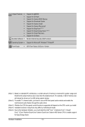
... Form Factor w ATX Form Factor; 30.5cm x 19.4cm (Note 1) Based on the CPU cooler you install. (Note 4) Available functions in EasyTune may differ by motherboard model. (Note 5) Due to the hardware limitation, you have to use an HD front panel audio module and enable the multi-channel audio feature through...
... Form Factor w ATX Form Factor; 30.5cm x 19.4cm (Note 1) Based on the CPU cooler you install. (Note 4) Available functions in EasyTune may differ by motherboard model. (Note 5) Due to the hardware limitation, you have to use an HD front panel audio module and enable the multi-channel audio feature through...
Manual
Page 13
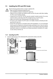
...the system bus frequency be inserted if oriented incorrectly. (Or you wish to set beyond the standard specifications, please do so according to GIGABYTE's website for the peripherals. It is not installed, otherwise overheating and dam- age of thermal grease on the computer if the CPU... cooler is not recommended that the motherboard supports the CPU. (Go to your hardware specifications including the CPU, graphics card, memory, hard drive, etc. 1-3-1 Installing the CPU A. ...
...the system bus frequency be inserted if oriented incorrectly. (Or you wish to set beyond the standard specifications, please do so according to GIGABYTE's website for the peripherals. It is not installed, otherwise overheating and dam- age of thermal grease on the computer if the CPU... cooler is not recommended that the motherboard supports the CPU. (Go to your hardware specifications including the CPU, graphics card, memory, hard drive, etc. 1-3-1 Installing the CPU A. ...
Manual
Page 14
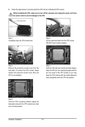
... socket cover from the power outlet to prevent damage to the CPU. Before installing the CPU, make sure to correctly install the CPU into the motherboard CPU socket.
... socket cover from the power outlet to prevent damage to the CPU. Before installing the CPU, make sure to correctly install the CPU into the motherboard CPU socket.
Manual
Page 15
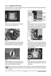
Check that the Male and Female push pins are joined closely. (Refer to the CPU fan header (CPU_FAN) on the motherboard. Step 4: You should hear a "click" when pushing down on the push pins diagonally. Step 6: Finally, attach the power connector of the CPU cooler to your ... the CPU, aligning the four push pins through the pin holes on the surface of arrow is to correctly install the CPU cooler on the motherboard. (The following procedure uses Intel® boxed cooler as the picture above shows, the installation is to the CPU. Push down each push pin. Use...
Check that the Male and Female push pins are joined closely. (Refer to the CPU fan header (CPU_FAN) on the motherboard. Step 4: You should hear a "click" when pushing down on the push pins diagonally. Step 6: Finally, attach the power connector of the CPU cooler to your ... the CPU, aligning the four push pins through the pin holes on the surface of arrow is to correctly install the CPU cooler on the motherboard. (The following procedure uses Intel® boxed cooler as the picture above shows, the installation is to the CPU. Push down each push pin. Use...
Manual
Page 16
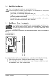
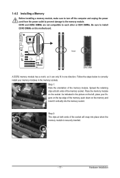
...memory of the memory. The four DDR2 memory sockets are unable to insert the memory, switch the direction. 1-4-1 Dual Channel Memory Configuration This motherboard provides four DDR2 memory sockets and supports Dual Channel Technology. Hardware Installation - 16 - If you begin to install the memory: • ... memory mode will automatically detect the specifications and capacity of the same capacity, brand, speed, and chips be used . (Go to GIGABYTE's website for the latest memory support list.) • Always turn off the computer and unplug the power cord from the power outlet before...
...memory of the memory. The four DDR2 memory sockets are unable to insert the memory, switch the direction. 1-4-1 Dual Channel Memory Configuration This motherboard provides four DDR2 memory sockets and supports Dual Channel Technology. Hardware Installation - 16 - If you begin to install the memory: • ... memory mode will automatically detect the specifications and capacity of the same capacity, brand, speed, and chips be used . (Go to GIGABYTE's website for the latest memory support list.) • Always turn off the computer and unplug the power cord from the power outlet before...
Manual
Page 17
... below to correctly install your fingers on the top edge of the socket will snap into the memory socket. Place the memory module on this motherboard. Notch DDR2 DIMM A DDR2 memory module has a notch, so it vertically into place when the memory module is securely inserted. - 17 - Spread the retaining clips...
... below to correctly install your fingers on the top edge of the socket will snap into the memory socket. Place the memory module on this motherboard. Notch DDR2 DIMM A DDR2 memory module has a notch, so it vertically into place when the memory module is securely inserted. - 17 - Spread the retaining clips...
Manual
Page 18
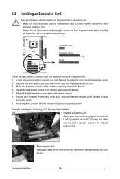
... a screw. 5. Hardware Installation - 18 - Remove the metal slot cover from the power outlet before you begin to install an expansion card: • Make sure the motherboard supports the expansion card. Example: Installing and Removing a PCI Express Graphics Card: • Installing a Graphics Card: Gently push down on the card until it is...
... a screw. 5. Hardware Installation - 18 - Remove the metal slot cover from the power outlet before you begin to install an expansion card: • Make sure the motherboard supports the expansion card. Example: Installing and Removing a PCI Express Graphics Card: • Installing a Graphics Card: Gently push down on the card until it is...
Manual
Page 19
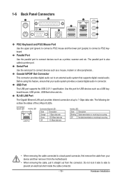
... port (green) to connect a PS/2 mouse and the lower port (purple) to an external audio system that your device and then remove it from the motherboard. • When removing the cable, pull it side to side to 1 Gbps data rate.
... port (green) to connect a PS/2 mouse and the lower port (purple) to an external audio system that your device and then remove it from the motherboard. • When removing the cable, pull it side to side to 1 Gbps data rate.
Manual
Page 21
... devices and your devices are compliant with the connectors you wish to connect. • Before installing the devices, be sure to the connector on the motherboard. - 21 -
... devices and your devices are compliant with the connectors you wish to connect. • Before installing the devices, be sure to the connector on the motherboard. - 21 -
Manual
Page 22
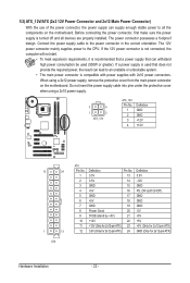
... power supply cable into pins under the protective cover when using a 2x12 power supply, remove the protective cover from the main power connector on the motherboard. The power connector possesses a foolproof design. If the 12V power connector is not connected, the computer will not start. • To meet expansion requirements, it... power connector mainly supplies power to the power connector in the correct orientation. If a power supply is turned off and all the components on the motherboard.
... power supply cable into pins under the protective cover when using a 2x12 power supply, remove the protective cover from the main power connector on the motherboard. The power connector possesses a foolproof design. If the 12V power connector is not connected, the computer will not start. • To meet expansion requirements, it... power connector mainly supplies power to the power connector in the correct orientation. If a power supply is turned off and all the components on the motherboard.
Manual
Page 23
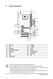
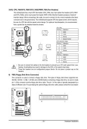
...Pin No. The pin 1 of the cable is used to locate pin 1 of floppy disk drives supported are not configuration jumper blocks. The motherboard supports CPU fan speed control, which requires the use of different color. For optimum heat dissipation, it in damage to the CPU or the ... This connector is typically designated by a stripe of a CPU fan with fan speed control design. 3/4/5) CPU_FAN/SYS_FAN1/SYS_FAN2/PWR_FAN (Fan Headers) The motherboard has a 4-pin CPU fan header (CPU_FAN), two 3-pin system fan headers (SYS_FAN1 and SYS_FAN2), and a 3-pin power fan header (PWR_FAN).
...Pin No. The pin 1 of the cable is used to locate pin 1 of floppy disk drives supported are not configuration jumper blocks. The motherboard supports CPU fan speed control, which requires the use of different color. For optimum heat dissipation, it in damage to the CPU or the ... This connector is typically designated by a stripe of a CPU fan with fan speed control design. 3/4/5) CPU_FAN/SYS_FAN1/SYS_FAN2/PWR_FAN (Fan Headers) The motherboard has a 4-pin CPU fan header (CPU_FAN), two 3-pin system fan headers (SYS_FAN1 and SYS_FAN2), and a 3-pin power fan header (PWR_FAN).
Manual
Page 26
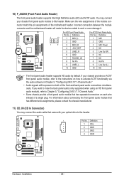
... Audio Header) The front panel audio header supports Intel High Definition audio (HD) and AC'97 audio. Incorrect connection between the module connector and the motherboard header will be present on each wire instead of a single plug. Definition Pin No. If your optical drive to work or even damage it. For... Front Panel Audio: For AC'97 Front Panel Audio: Pin No. You may connect the audio cable that has separated connectors on both of the motherboard header. Definition 1 CD-L 2 GND 3 GND 4 CD-R Hardware Installation - 26 -
... Audio Header) The front panel audio header supports Intel High Definition audio (HD) and AC'97 audio. Incorrect connection between the module connector and the motherboard header will be present on each wire instead of a single plug. Definition Pin No. If your optical drive to work or even damage it. For... Front Panel Audio: For AC'97 Front Panel Audio: Pin No. You may connect the audio cable that has separated connectors on both of the motherboard header. Definition 1 CD-L 2 GND 3 GND 4 CD-R Hardware Installation - 26 -
Manual
Page 27
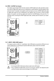
... your graphics card if you wish to connect an HDMI display to the graphics card and have digital audio output from your motherboard to the USB bracket. - 27 - Hardware Installation For information about connecting the S/PDIF digital audio cable, carefully read the manual for your computer and unplug ...
... your graphics card if you wish to connect an HDMI display to the graphics card and have digital audio output from your motherboard to the USB bracket. - 27 - Hardware Installation For information about connecting the S/PDIF digital audio cable, carefully read the manual for your computer and unplug ...
Manual
Page 28
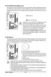
... CMOS values (e.g. Replace the battery when the battery voltage drops to Chapter 2, "BIOS Setup," for 5 seconds.) 3. Failure to do so may cause damage to the motherboard. • After system restart, go to BIOS Setup to load factory defaults (select Load Optimized efaults) or manually configure the BIOS settings (refer to a low...
... CMOS values (e.g. Replace the battery when the battery voltage drops to Chapter 2, "BIOS Setup," for 5 seconds.) 3. Failure to do so may cause damage to the motherboard. • After system restart, go to BIOS Setup to load factory defaults (select Load Optimized efaults) or manually configure the BIOS settings (refer to a low...


