
Manual
Page 1
GA-P35T-DQ6 LGA775 socket motherboard for Intel® CoreTM processor family/ Intel® Pentium® processor family/Intel® Celeron® processor family User's Manual Rev. 1003 12ME-P35TDQ6-1003R * The WEEE marking on the product indicates this product must not be disposed of with user's other household waste and must be handed over to a designated collection point for the recycling of waste electrical and electronic equipment!! * The WEEE marking applies only in European Union's member states.
GA-P35T-DQ6 LGA775 socket motherboard for Intel® CoreTM processor family/ Intel® Pentium® processor family/Intel® Celeron® processor family User's Manual Rev. 1003 12ME-P35TDQ6-1003R * The WEEE marking on the product indicates this product must not be disposed of with user's other household waste and must be handed over to a designated collection point for the recycling of waste electrical and electronic equipment!! * The WEEE marking applies only in European Union's member states.

Manual
Page 2
Motherboard GA-P35T-DQ6 Apr. 20, 2007 Motherboard GA-P35T-DQ6 Apr. 20, 2007
Motherboard GA-P35T-DQ6 Apr. 20, 2007 Motherboard GA-P35T-DQ6 Apr. 20, 2007
Manual
Page 3
... may be reproduced, copied, translated, transmitted, or published in this product, GIGABYTE provides the following types of documentations: „ For quick set-up of GIGABYTE branded motherboards. For product-related information, check on our website at: http://www.gigabyte.com.tw Identifying Your Motherboard Revision The revision number on our website. Copyright © 2007 GIGA...
... may be reproduced, copied, translated, transmitted, or published in this product, GIGABYTE provides the following types of documentations: „ For quick set-up of GIGABYTE branded motherboards. For product-related information, check on our website at: http://www.gigabyte.com.tw Identifying Your Motherboard Revision The revision number on our website. Copyright © 2007 GIGA...

Manual
Page 4
Table of Contents OptionalItems ...6 Box Contents ...6 GA-P35T-DQ6 Motherboard Layout 7 Block Diagram ...8 Chapter 1 Hardware Installation 9 1-1 Installation Precautions 9 1-2 Product Specifications 10 1-3 Installing the CPU and CPU Cooler 13 1-3-1 Installing the CPU 13 1-3-2 Installing the CPU Cooler 15 1-3-3 Removing the Crazy Cool Heatsink from the Back of the Motherboard ..... 16 1-4 Installing the Memory 17 1-4-1 Dual Channel Memory...
Table of Contents OptionalItems ...6 Box Contents ...6 GA-P35T-DQ6 Motherboard Layout 7 Block Diagram ...8 Chapter 1 Hardware Installation 9 1-1 Installation Precautions 9 1-2 Product Specifications 10 1-3 Installing the CPU and CPU Cooler 13 1-3-1 Installing the CPU 13 1-3-2 Installing the CPU Cooler 15 1-3-3 Removing the Crazy Cool Heatsink from the Back of the Motherboard ..... 16 1-4 Installing the Memory 17 1-4-1 Dual Channel Memory...

Manual
Page 6
The box contents are for reference only and the actual items shall depend on product package you obtain. Box Contents GA-P35T-DQ6 motherboard Motherboard driver disk User's Manual Quick Installation Guide Intel® LGA775 CPU Installation Guide One IDE cable and one floppy disk drive cable Four SATA 3Gb/s ...
The box contents are for reference only and the actual items shall depend on product package you obtain. Box Contents GA-P35T-DQ6 motherboard Motherboard driver disk User's Manual Quick Installation Guide Intel® LGA775 CPU Installation Guide One IDE cable and one floppy disk drive cable Four SATA 3Gb/s ...

Manual
Page 7
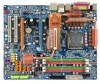
GA-P35T-DQ6 Motherboard Layout KB_MS COAXIAL OPTICAL SYS_FAN1 ATX_12V_2X LGA775 PWR_FAN PCIE_12V ATX COMA LPT USB 1394 GA-P35T-DQ6 USB LAN F_AUDIO CPU_FAN AUDIO PCIE_1 Intel® P35 FDD RTL8111B PCIE_16_1 NB_FAN DDRIII1 DDRIII2 DDRIII3 DDRIII4 CODEC CD_IN PCIE_2 BP_BIOS MAIN_BIOS PCIE_3 PCIE_16_2 BATTERY CLR_CMOS PCI1 TSB43AB23 IT8718 PCI2 SPDIF_IN TPM CI SYS_FAN2 F_USB4 F_USB3 F_USB2 F_USB1 Intel® ICH9R SATAII4 SATAII5 SATAII0 SATAII1 SATAII2 SATAII3 GIGABYTE SATA2 IDE F1_1394 F2_1394 PWR_LED F_PANEL GSATAII0 GSATAII1 - 7 -
GA-P35T-DQ6 Motherboard Layout KB_MS COAXIAL OPTICAL SYS_FAN1 ATX_12V_2X LGA775 PWR_FAN PCIE_12V ATX COMA LPT USB 1394 GA-P35T-DQ6 USB LAN F_AUDIO CPU_FAN AUDIO PCIE_1 Intel® P35 FDD RTL8111B PCIE_16_1 NB_FAN DDRIII1 DDRIII2 DDRIII3 DDRIII4 CODEC CD_IN PCIE_2 BP_BIOS MAIN_BIOS PCIE_3 PCIE_16_2 BATTERY CLR_CMOS PCI1 TSB43AB23 IT8718 PCI2 SPDIF_IN TPM CI SYS_FAN2 F_USB4 F_USB3 F_USB2 F_USB1 Intel® ICH9R SATAII4 SATAII5 SATAII0 SATAII1 SATAII2 SATAII3 GIGABYTE SATA2 IDE F1_1394 F2_1394 PWR_LED F_PANEL GSATAII0 GSATAII1 - 7 -

Manual
Page 9
...required for warranty validation. • Always remove the AC power by your hardware components are connected. • To prevent damage to the motherboard, do not have an ESD wrist strap, keep your hands dry and first touch a metal object to eliminate static electricity. • ...When connecting hardware components to the internal connectors on the power, make sure they are connected tightly and securely. • When handling the motherboard, avoid touching any metal leads or connectors. • It is best to wear an electrostatic discharge (ESD) wrist strap when handling electronic ...
...required for warranty validation. • Always remove the AC power by your hardware components are connected. • To prevent damage to the motherboard, do not have an ESD wrist strap, keep your hands dry and first touch a metal object to eliminate static electricity. • ...When connecting hardware components to the internal connectors on the power, make sure they are connected tightly and securely. • When handling the motherboard, avoid touching any metal leads or connectors. • It is best to wear an electrostatic discharge (ESD) wrist strap when handling electronic ...

Manual
Page 10
.../Intel® Pentium® 4 processor/ Intel® Celeron® D processor in the LGA 775 package (Go to GIGABYTE's website for the latest CPU support list.) Š Support for Intel® Hyper-Threading Technology Š L2 cache varies..., SATAII3, SATAII4, SATAII5) supporting up to 6 SATA 3Gb/s devices - Support for SATA RAID 0, RAID 1, RAID 5, and RAID 10 Š GIGABYTE SATA2 chip: - 1 x IDE connector supporting ATA-133/100/66/33 and up to 2 IDE devices - 2 x SATA 3 Gb/s connectors ...5V DDR3 DIMM sockets supporting up to the internal IEEE 1394 headers) GA-P35T-DQ6 Motherboard - 10 -
.../Intel® Pentium® 4 processor/ Intel® Celeron® D processor in the LGA 775 package (Go to GIGABYTE's website for the latest CPU support list.) Š Support for Intel® Hyper-Threading Technology Š L2 cache varies..., SATAII3, SATAII4, SATAII5) supporting up to 6 SATA 3Gb/s devices - Support for SATA RAID 0, RAID 1, RAID 5, and RAID 10 Š GIGABYTE SATA2 chip: - 1 x IDE connector supporting ATA-133/100/66/33 and up to 2 IDE devices - 2 x SATA 3 Gb/s connectors ...5V DDR3 DIMM sockets supporting up to the internal IEEE 1394 headers) GA-P35T-DQ6 Motherboard - 10 -

Manual
Page 12
Adjust PCI Express x16 frequency from 100 MHz to 700 MHz with 0.05V increment - GA-P35T-DQ6 Motherboard - 12 - Increase (G)MCH voltage by 0.025V to 0.375V with 1 MHz increment Š Support for Virtual Dual BIOS Š Norton Internet Security (OEM version) Š ... second PCI Express x16 slot (PCIE_16_2) is in use, the three PCI Express x1 slots become unavailable. (Note 3) Available functions in Easytune may differ by motherboard model. (Note 4) The adjustable CPU voltage range depends on the CPU being used. (Note 5) Due to chipset limitation, Intel ICH9R RAID driver does not...
Adjust PCI Express x16 frequency from 100 MHz to 700 MHz with 0.05V increment - GA-P35T-DQ6 Motherboard - 12 - Increase (G)MCH voltage by 0.025V to 0.375V with 1 MHz increment Š Support for Virtual Dual BIOS Š Norton Internet Security (OEM version) Š ... second PCI Express x16 slot (PCIE_16_2) is in use, the three PCI Express x1 slots become unavailable. (Note 3) Available functions in Easytune may differ by motherboard model. (Note 4) The adjustable CPU voltage range depends on the CPU being used. (Note 5) Due to chipset limitation, Intel ICH9R RAID driver does not...

Manual
Page 13
... cord from the power outlet before you begin to install the CPU: • Make sure that the motherboard supports the CPU. (Go to GIGABYTE's website for the peripherals. Locate the alignment keys on the motherboard CPU socket and the notches on the CPU Hardware Installation Notch Triangle Pin One Marking on the CPU...
... cord from the power outlet before you begin to install the CPU: • Make sure that the motherboard supports the CPU. (Go to GIGABYTE's website for the peripherals. Locate the alignment keys on the motherboard CPU socket and the notches on the CPU Hardware Installation Notch Triangle Pin One Marking on the CPU...

Manual
Page 14
... one marking (triangle) with the pin one corner of the CPU socket (or you may align the CPU notches with your thumb and index fingers. GA-P35T-DQ6 Motherboard - 14 - English B. Follow the steps below to the CPU. CPU Socket Lever Step 1: Completely raise the CPU socket lever. Step 4: Hold the CPU with the... CPU into its locked position. Step 5: Once the CPU is properly inserted, replace the load plate and push the CPU socket lever back into the motherboard CPU socket. Step 3: Lift the metal load plate on the CPU socket. Step 2: Remove the protective socket cover.
... one marking (triangle) with the pin one corner of the CPU socket (or you may align the CPU notches with your thumb and index fingers. GA-P35T-DQ6 Motherboard - 14 - English B. Follow the steps below to the CPU. CPU Socket Lever Step 1: Completely raise the CPU socket lever. Step 4: Hold the CPU with the... CPU into its locked position. Step 5: Once the CPU is properly inserted, replace the load plate and push the CPU socket lever back into the motherboard CPU socket. Step 3: Lift the metal load plate on the CPU socket. Step 2: Remove the protective socket cover.

Manual
Page 15
..., on the contrary, is complete. Hardware Installation English 1-3-2 Installing the CPU Cooler Follow the steps below to correctly install the CPU cooler on the motherboard. (The following procedure uses Intel® boxed cooler as the picture above, the installation is to install.) Step 3: Place the cooler atop the ...CPU, aligning the four push pins through the pin holes on the motherboard. Direction of the Arrow Sign on the Male Push Pin Male Push Pin The Top of Female Push Pin Female Push Pin Step 2: Before...
..., on the contrary, is complete. Hardware Installation English 1-3-2 Installing the CPU Cooler Follow the steps below to correctly install the CPU cooler on the motherboard. (The following procedure uses Intel® boxed cooler as the picture above, the installation is to install.) Step 3: Place the cooler atop the ...CPU, aligning the four push pins through the pin holes on the motherboard. Direction of the Arrow Sign on the Male Push Pin Male Push Pin The Top of Female Push Pin Female Push Pin Step 2: Before...

Manual
Page 16
...to replace the copper fin.) Refer to the left and remove the screws. English 1-3-3 Removing the Crazy Cool Heatsink from the Back of the Motherboard To install a non-Intel CPU cooler that requires extra mounting holes, follow the steps below remove the Crazy Cool heatsink from the products illustrated...your CPU cooler installation manual for the other spring screw. Tools needed: 1. Step 7: Finally, you may vary in the picture to the full. GA-P35T-DQ6 Motherboard - 16 - Do not remove the spring screws. Step 5: Push down on one of the two spring screws and put the nut on the ...
...to replace the copper fin.) Refer to the left and remove the screws. English 1-3-3 Removing the Crazy Cool Heatsink from the Back of the Motherboard To install a non-Intel CPU cooler that requires extra mounting holes, follow the steps below remove the Crazy Cool heatsink from the products illustrated...your CPU cooler installation manual for the other spring screw. Tools needed: 1. Step 7: Finally, you may vary in the picture to the full. GA-P35T-DQ6 Motherboard - 16 - Do not remove the spring screws. Step 5: Push down on one of the two spring screws and put the nut on the ...

Manual
Page 17
...to install the memory: • Make sure that memory of the same capacity, brand, speed, and chips be used . (Go to GIGABYTE's website for optimum performance. English 1-4 Installing the Memory Read the following : Channel 0: DDRIII1, DDRIII2 Channel 1: DDRIII3, DDRIII4 Dual Channel...flexibility to upgrade by allowing different memory sizes to insert the memory, switch the direction. 1-4-1 Dual Channel Memory Configuration This motherboard provides four DDR3 memory sockets and supports Dual Channel Technology. Hardware Installation When enabling Dual Channel mode with two or four...
...to install the memory: • Make sure that memory of the same capacity, brand, speed, and chips be used . (Go to GIGABYTE's website for optimum performance. English 1-4 Installing the Memory Read the following : Channel 0: DDRIII1, DDRIII2 Channel 1: DDRIII3, DDRIII4 Dual Channel...flexibility to upgrade by allowing different memory sizes to insert the memory, switch the direction. 1-4-1 Dual Channel Memory Configuration This motherboard provides four DDR3 memory sockets and supports Dual Channel Technology. Hardware Installation When enabling Dual Channel mode with two or four...

Manual
Page 18
... left, place your memory modules in one direction. Follow the steps below to correctly install your fingers on the top edge of the memory module. GA-P35T-DQ6 Motherboard - 18 - English 1-4-2 Installing a Memory Before installing a memory module , make sure to turn off the computer and unplug the power cord from the power outlet to...
... left, place your memory modules in one direction. Follow the steps below to correctly install your fingers on the top edge of the memory module. GA-P35T-DQ6 Motherboard - 18 - English 1-4-2 Installing a Memory Before installing a memory module , make sure to turn off the computer and unplug the power cord from the power outlet to...
Manual
Page 19
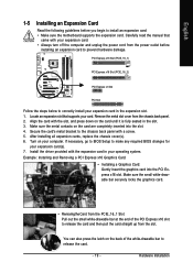
... expansion card(s). 7. English 1-5 Installing an Expansion Card Read the following guidelines before installing an expansion card to install an expansion card: • Make sure the motherboard supports the expansion card. Carefully read the manual that supports your operating system. PCI Express x16 Slot (PCIE_16_1) PCI Express x16 Slot (PCIE_16_2) PCI Express...
... expansion card(s). 7. English 1-5 Installing an Expansion Card Read the following guidelines before installing an expansion card to install an expansion card: • Make sure the motherboard supports the expansion card. Carefully read the manual that supports your operating system. PCI Express x16 Slot (PCIE_16_1) PCI Express x16 Slot (PCIE_16_2) PCI Express...

Manual
Page 20
GA-P35T-DQ6 Motherboard - 20 - When you install two graphics cards, connect the power cable from the slot. • The motherboard provides a PCIE_12V power connector, which can supply extra power to this connector. English • Removing the Card from the PCIE_16_2 Slot: Press the white latch at the end of the PCI Express x16 slot to release the card and then pull the card straight up from your power supply to the onboard PCI Express x16 slots.
GA-P35T-DQ6 Motherboard - 20 - When you install two graphics cards, connect the power cable from the slot. • The motherboard provides a PCIE_12V power connector, which can supply extra power to this connector. English • Removing the Card from the PCIE_16_2 Slot: Press the white latch at the end of the PCI Express x16 slot to release the card and then pull the card straight up from your power supply to the onboard PCI Express x16 slots.

Manual
Page 21
... the internal SATA port(s) to the chassis back panel. • Turn off the power of the SATA signal cable and SATA power cable to your motherboard. English 1-6 Installing the SATA Bracket The SATA bracket allows you only need to connect the SATA signal cable. Step 2: Connect the SATA cable from the...
... the internal SATA port(s) to the chassis back panel. • Turn off the power of the SATA signal cable and SATA power cable to your motherboard. English 1-6 Installing the SATA Bracket The SATA bracket allows you only need to connect the SATA signal cable. Step 2: Connect the SATA cable from the...

Manual
Page 22
...Off No data transmission or receiving is also called a printer port. Use this feature, ensure that your device and then remove it from the motherboard. • When removing the cable, pull it side to side to 1 Gbps data rate. Do not rock it straight out from the ... port is occurring • When removing the cable connected to connect devices such as an USB keyboard/mouse, USB printer, USB flash drive and etc. GA-P35T-DQ6 Motherboard - 22 - English 1-7 Back Panel Connectors PS/2 Keyboard and PS/2 Mouse Port Use the upper port (green) to connect a PS/2 mouse and ...
...Off No data transmission or receiving is also called a printer port. Use this feature, ensure that your device and then remove it from the motherboard. • When removing the cable, pull it side to side to 1 Gbps data rate. Do not rock it straight out from the ... port is occurring • When removing the cable connected to connect devices such as an USB keyboard/mouse, USB printer, USB flash drive and etc. GA-P35T-DQ6 Motherboard - 22 - English 1-7 Back Panel Connectors PS/2 Keyboard and PS/2 Mouse Port Use the upper port (green) to connect a PS/2 mouse and ...

Manual
Page 24
... compliant with the connectors you wish to connect. • Before installing the devices, be sure to the connector on the computer, make sure your computer. GA-P35T-DQ6 Motherboard - 24 - English 1-8 Internal Connectors 1 43 5 7 2 8 14 6 20 10 22 15 9 21 16 19 4 18 17 11 12 13 1) ATX_12V_2X 2) ATX (Power Connector) 3) CPU_FAN 4) SYS_FAN1/SYS_FAN2...) SPDIF_IN 17) F_USB1/F_USB2/F_USB3/F_USB4 18) F1_1394/F2_1394 19) TPM 20) CLR_CMOS 21) CI 22) BATTERY Read the following guidelines before turning on the motherboard.
... compliant with the connectors you wish to connect. • Before installing the devices, be sure to the connector on the computer, make sure your computer. GA-P35T-DQ6 Motherboard - 24 - English 1-8 Internal Connectors 1 43 5 7 2 8 14 6 20 10 22 15 9 21 16 19 4 18 17 11 12 13 1) ATX_12V_2X 2) ATX (Power Connector) 3) CPU_FAN 4) SYS_FAN1/SYS_FAN2...) SPDIF_IN 17) F_USB1/F_USB2/F_USB3/F_USB4 18) F1_1394/F2_1394 19) TPM 20) CLR_CMOS 21) CI 22) BATTERY Read the following guidelines before turning on the motherboard.


