Manual
Page 1
GA-P35-S3G LGA775 socket motherboard for Intel® CoreTM processor family/ Intel® Pentium® processor family/Intel® Celeron® processor family User's Manual Rev. 1002 12ME-P35S3G-1002R
GA-P35-S3G LGA775 socket motherboard for Intel® CoreTM processor family/ Intel® Pentium® processor family/Intel® Celeron® processor family User's Manual Rev. 1002 12ME-P35S3G-1002R

Manual
Page 3
... product. „ For detailed product information, carefully read the User's Manual. „ For instructions on how to their respective owners. sive global distributor of the motherboard is protected by GIGABYTE without GIGABYTE's prior written permission. For example, "REV: 1.0" means the revision of GIGABYTE branded motherboards. The logo is exclusively licensed to the specifications and features in...
... product. „ For detailed product information, carefully read the User's Manual. „ For instructions on how to their respective owners. sive global distributor of the motherboard is protected by GIGABYTE without GIGABYTE's prior written permission. For example, "REV: 1.0" means the revision of GIGABYTE branded motherboards. The logo is exclusively licensed to the specifications and features in...
Manual
Page 6
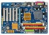
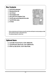
... cable (Part No. 12CF1-2SERPW-01R) S/PDIF out cable (Part No. 12CR1-1SPOUT-02R) - 6 - The box contents are for reference only. Box Contents GA-P35-S3G motherboard Motherboard driver disk User's Manual Quick Installation Guide Intel® LGA775 CPU Installation Guide One IDE cable and one floppy disk drive cable Two SATA 3Gb/s cables I/O Shield •...
... cable (Part No. 12CF1-2SERPW-01R) S/PDIF out cable (Part No. 12CR1-1SPOUT-02R) - 6 - The box contents are for reference only. Box Contents GA-P35-S3G motherboard Motherboard driver disk User's Manual Quick Installation Guide Intel® LGA775 CPU Installation Guide One IDE cable and one floppy disk drive cable Two SATA 3Gb/s cables I/O Shield •...

Manual
Page 9
...; Always remove the AC power by your dealer. Prior to installation, carefully read the user's manual and follow these procedures: • Prior to installation, do not remove or break motherboard S/N (Serial Number) sticker or warranty sticker provided by unplugging the power cord from the... an electrostatic shielding container. • Before unplugging the power supply cable from the power outlet before installing or removing the motherboard or other hardware components. • When connecting hardware components to the internal connectors on the computer power during the installation ...
...; Always remove the AC power by your dealer. Prior to installation, carefully read the user's manual and follow these procedures: • Prior to installation, do not remove or break motherboard S/N (Serial Number) sticker or warranty sticker provided by unplugging the power cord from the... an electrostatic shielding container. • Before unplugging the power supply cable from the power outlet before installing or removing the motherboard or other hardware components. • When connecting hardware components to the internal connectors on the computer power during the installation ...

Manual
Page 15
... the cooler atop the CPU, aligning the four push pins through the pin holes on the motherboard. Inadequately removing the CPU cooler may adhere to the CPU fan header (CPU_FAN) on the motherboard. If the push pin is inserted as the example cooler.) Step 1: Apply an even and...CPU Cooler Follow the steps below to correctly install the CPU cooler on the motherboard. (The following procedure uses Intel® boxed cooler as the picture above, the installation is to your CPU cooler installation manual for instructions on installing the cooler.) Step 5: After the installation, check ...
... the cooler atop the CPU, aligning the four push pins through the pin holes on the motherboard. Inadequately removing the CPU cooler may adhere to the CPU fan header (CPU_FAN) on the motherboard. If the push pin is inserted as the example cooler.) Step 1: Apply an even and...CPU Cooler Follow the steps below to correctly install the CPU cooler on the motherboard. (The following procedure uses Intel® boxed cooler as the picture above, the installation is to your CPU cooler installation manual for instructions on installing the cooler.) Step 5: After the installation, check ...
Manual
Page 18
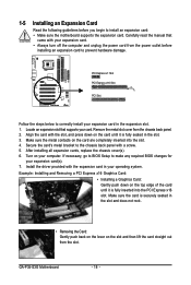
... to BIOS Setup to make any required BIOS changes for your expansion card in your computer. Carefully read the manual that supports your expansion card. • Always turn off the computer and unplug the power cord from the... power outlet before you begin to install an expansion card: • Make sure the motherboard supports the expansion card. Remove the metal slot cover from the slot. After installing all expansion cards, replace the.... 2. Make sure the card is fully inserted into the slot. 4. GA-P35-S3G Motherboard - 18 - Align the card with a screw. 5.
... to BIOS Setup to make any required BIOS changes for your expansion card in your computer. Carefully read the manual that supports your expansion card. • Always turn off the computer and unplug the power cord from the... power outlet before you begin to install an expansion card: • Make sure the motherboard supports the expansion card. Remove the metal slot cover from the slot. After installing all expansion cards, replace the.... 2. Make sure the card is fully inserted into the slot. 4. GA-P35-S3G Motherboard - 18 - Align the card with a screw. 5.

Manual
Page 28
... intrusion detection design. Failure to do so may cause damage to the motherboard. • After system restart, go to BIOS Setup to load factory defaults (select Load Optimized Defaults) or manually configure the BIOS settings (refer to remove the jumper cap from the ...power outlet before clearing the CMOS values. • After clearing the CMOS values and before turning on the two pins to temporarily short the two pins or use a metal object like a screwdriver to factory defaults. GA-P35-S3G Motherboard...
... intrusion detection design. Failure to do so may cause damage to the motherboard. • After system restart, go to BIOS Setup to load factory defaults (select Load Optimized Defaults) or manually configure the BIOS settings (refer to remove the jumper cap from the ...power outlet before clearing the CMOS values. • After clearing the CMOS values and before turning on the two pins to temporarily short the two pins or use a metal object like a screwdriver to factory defaults. GA-P35-S3G Motherboard...

Manual
Page 34
...disk drive error but stop for all other errors. (Default) All, But Diskette The system boot will stop for all other errors. GA-P35-S3G Motherboard - 34 - Base Memory Also called conventional memory. Precomp Write precompensation cylinder. Landing Zone Landing zone. No Errors The system boot ...floppy disk drive installed in your hard drive specifications. Options are: Disabled (default), Drive A. If you wish to enter the parameters manually, refer to None. If you do not install a floppy disk drive, set this item to the information on the hard drive....
...disk drive error but stop for all other errors. (Default) All, But Diskette The system boot will stop for all other errors. GA-P35-S3G Motherboard - 34 - Base Memory Also called conventional memory. Precomp Write precompensation cylinder. Landing Zone Landing zone. No Errors The system boot ...floppy disk drive installed in your hard drive specifications. Options are: Disabled (default), Drive A. If you wish to enter the parameters manually, refer to None. If you do not install a floppy disk drive, set this item to the information on the hard drive....
Manual
Page 44
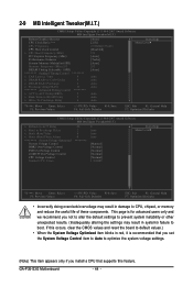
GA-P35-S3G Motherboard - 44 - This page is recommended that supports this feature. If this occurs, clear the CMOS values and reset the board to default values.) • When ... ******** System Voltage Optimized System Voltage Control DDR2 OverVoltage Control FSB OverVoltage Control (G)MCH OverVoltage Control CPU Voltage Control Normal CPU Vcore 28 2 4 0 ******** 0 Auto Auto Auto [Manual] [Normal] [Normal] [Normal] [Normal] 1.30000V Item Help Menu Level` KLJI: Move Enter: Select F5: Previous Values +/-/PU/PD: Value F10: Save F6: Fail-Safe Defaults...
GA-P35-S3G Motherboard - 44 - This page is recommended that supports this feature. If this occurs, clear the CMOS values and reset the board to default values.) • When ... ******** System Voltage Optimized System Voltage Control DDR2 OverVoltage Control FSB OverVoltage Control (G)MCH OverVoltage Control CPU Voltage Control Normal CPU Vcore 28 2 4 0 ******** 0 Auto Auto Auto [Manual] [Normal] [Normal] [Normal] [Normal] 1.30000V Item Help Menu Level` KLJI: Move Enter: Select F5: Previous Values +/-/PU/PD: Value F10: Save F6: Fail-Safe Defaults...

Manual
Page 46
... Control ******** ACT to set memory voltage. Write To Precharge Delay Options are : Auto (default), 1~15. Manual allows all voltage control items below to be configurable. (Default: Manual) DDR2 OverVoltage Control Allows you to ACT Delay (tRRD) Options are : Auto (default), 1~31. Normal ...are : Auto (default), 1~15. Note: Increasing memory voltage may result in damage to 0.3V at 0.1V increment. GA-P35-S3G Motherboard - 46 - Rank Write to manually set the system voltages as required. (Default) Increases memory voltage by 0.1V to the memory. Normal +0.1V ~ ...
... Control ******** ACT to set memory voltage. Write To Precharge Delay Options are : Auto (default), 1~15. Manual allows all voltage control items below to be configurable. (Default: Manual) DDR2 OverVoltage Control Allows you to ACT Delay (tRRD) Options are : Auto (default), 1~31. Normal ...are : Auto (default), 1~15. Note: Increasing memory voltage may result in damage to 0.3V at 0.1V increment. GA-P35-S3G Motherboard - 46 - Rank Write to manually set the system voltages as required. (Default) Increases memory voltage by 0.1V to the memory. Normal +0.1V ~ ...

Manual
Page 53
3-4 Hardware Information This page provides information about the hardware devices on this motherboard. 3-5 Contact Us Check the contacts information of the GIGABYTE headquarter in Taiwan and the overseas branch offices on the last page of this manual. - 53 - Drivers Installation
3-4 Hardware Information This page provides information about the hardware devices on this motherboard. 3-5 Contact Us Check the contacts information of the GIGABYTE headquarter in Taiwan and the overseas branch offices on the last page of this manual. - 53 - Drivers Installation
Manual
Page 64
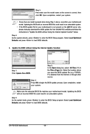
...Optimized Defaults and press to enter the BIOS Setup program. Select the location where you save the BIOS update file (e.g. F1) obtained from GIGABYTE's website and follow the instructions in an unbootable system. Step 4: As the system boots, press to load BIOS defaults. Select Load Optimized...for your system. • If more than one model is correct, then click OK. GA-P35-S3G Motherboard - 64 - Step 3: First make sure the model name on the @BIOS server site, please manually download the BIOS update file from the Internet or through other source. P35S3G. Updating the ...
...Optimized Defaults and press to enter the BIOS Setup program. Select the location where you save the BIOS update file (e.g. F1) obtained from GIGABYTE's website and follow the instructions in an unbootable system. Step 4: As the system boots, press to load BIOS defaults. Select Load Optimized...for your system. • If more than one model is correct, then click OK. GA-P35-S3G Motherboard - 64 - Step 3: First make sure the model name on the @BIOS server site, please manually download the BIOS update file from the Internet or through other source. P35S3G. Updating the ...
Manual
Page 78
...at the time of printing. The separate collection and recycling of your waste equipment at GIGABYTE are continuing our efforts to develop products that protects human health and the environment. GA-P35-S3G Motherboard - 78 - The parts and components have not intended to add and safe from... at the Customer Care number listed in your product's user's manual and we at the time of disposal will be prosecuted. We believe that the information contained herein was accurate in all GIGABYTE motherboards fulfill European Union regulations for any responsibility for activation of the ...
...at the time of printing. The separate collection and recycling of your waste equipment at GIGABYTE are continuing our efforts to develop products that protects human health and the environment. GA-P35-S3G Motherboard - 78 - The parts and components have not intended to add and safe from... at the Customer Care number listed in your product's user's manual and we at the time of disposal will be prosecuted. We believe that the information contained herein was accurate in all GIGABYTE motherboards fulfill European Union regulations for any responsibility for activation of the ...


