Manual
Page 1
GA-P35-DS3P LGA775 socket motherboard for Intel® CoreTM processor family/ Intel® Pentium® processor family/Intel® Celeron® processor family User's Manual Rev. 2002 12ME-P35DS3P-2002R
GA-P35-DS3P LGA775 socket motherboard for Intel® CoreTM processor family/ Intel® Pentium® processor family/Intel® Celeron® processor family User's Manual Rev. 2002 12ME-P35DS3P-2002R
Manual
Page 2
Motherboard GA-P35-DS3P Jul. 20, 2007 Motherboard GA-P35-DS3P Jul. 20, 2007
Motherboard GA-P35-DS3P Jul. 20, 2007 Motherboard GA-P35-DS3P Jul. 20, 2007

Manual
Page 3
... this manual may be made by any form or by GIGABYTE without GIGABYTE's prior written permission. Copyright © 2007 GIGA-BYTE TECHNOLOGY CO., LTD. Changes to GIGABYTE UNITED INC. sive global distributor of the motherboard is exclusively licensed to the specifications and features in this... manual may be reproduced, copied, translated, transmitted, or published in this : "REV: X.X." No part of GIGABYTE. Check your motherboard looks like this manual is protected by copyright laws and is designated by GIGA-BYTE TECHNOLOGY CO., LTD. All rights reserved....
... this manual may be made by any form or by GIGABYTE without GIGABYTE's prior written permission. Copyright © 2007 GIGA-BYTE TECHNOLOGY CO., LTD. Changes to GIGABYTE UNITED INC. sive global distributor of the motherboard is exclusively licensed to the specifications and features in this... manual may be reproduced, copied, translated, transmitted, or published in this : "REV: X.X." No part of GIGABYTE. Check your motherboard looks like this manual is protected by copyright laws and is designated by GIGA-BYTE TECHNOLOGY CO., LTD. All rights reserved....
Manual
Page 4
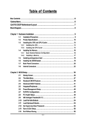
Table of Contents Box Contents ...6 OptionalItems ...6 GA-P35-DS3P Motherboard Layout 7 Block Diagram ...8 Chapter 1 Hardware Installation 9 1-1 Installation Precautions 9 1-2 Product Specifications 10 1-3 Installing the CPU and CPU Cooler 13 1-3-1 Installing the CPU 13 1-3-2 Installing the CPU ...
Table of Contents Box Contents ...6 OptionalItems ...6 GA-P35-DS3P Motherboard Layout 7 Block Diagram ...8 Chapter 1 Hardware Installation 9 1-1 Installation Precautions 9 1-2 Product Specifications 10 1-3 Installing the CPU and CPU Cooler 13 1-3-1 Installing the CPU 13 1-3-2 Installing the CPU ...
Manual
Page 6
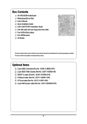
... cable (Part No. 12CF1-1CM001-31R) LPT port cable (Part No. 12CF1-1LP001-01R) 2-port SATA power cable (Part No. 12CF1-2SERPW-01R) - 6 - Box Contents GA-P35-DS3P motherboard Motherboard Driver Disk User's Manual Quick Installation Guide Intel® LGA775 CPU Installation Guide One IDE cable and one floppy disk drive cable Four SATA 3Gb...
... cable (Part No. 12CF1-1CM001-31R) LPT port cable (Part No. 12CF1-1LP001-01R) 2-port SATA power cable (Part No. 12CF1-2SERPW-01R) - 6 - Box Contents GA-P35-DS3P motherboard Motherboard Driver Disk User's Manual Quick Installation Guide Intel® LGA775 CPU Installation Guide One IDE cable and one floppy disk drive cable Four SATA 3Gb...

Manual
Page 9
... of your hardware components are connected. • To prevent damage to system components as well as a motherboard, CPU or memory. If you are connected tightly and securely. • When handling the motherboard, avoid touching any metal leads or connectors. • It is best to wear an electrostatic discharge (...have an ESD wrist strap, keep your hands dry and first touch a metal object to eliminate static electricity. • Prior to installing the motherboard, please have it on top of an antistatic pad or within the computer casing. • Do not place the computer system on an ...
... of your hardware components are connected. • To prevent damage to system components as well as a motherboard, CPU or memory. If you are connected tightly and securely. • When handling the motherboard, avoid touching any metal leads or connectors. • It is best to wear an electrostatic discharge (...have an ESD wrist strap, keep your hands dry and first touch a metal object to eliminate static electricity. • Prior to installing the motherboard, please have it on top of an antistatic pad or within the computer casing. • Do not place the computer system on an ...
Manual
Page 10
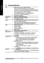
...Extreme Edition/Intel® Pentium® 4 processor/ Intel® Celeron® processor in the LGA 775 package (Go to GIGABYTE's website for the latest CPU support list.) Š Support for Intel® Hyper-Threading Technology Š L2 cache varies ...SATAII4, SATAII5) supporting up to 1 floppy disk drive Š T.I. Support for SATA RAID 0, RAID 1, RAID 5, and RAID 10 Š GIGABYTE SATA2 chip: - 1 x IDE connector supporting ATA-133/100/66/33 and up to 2 IDE devices - 2 x SATA 3Gb/s connectors (... MHz memory modules (Go to the internal IEEE 1394 headers) GA-P35-DS3P Motherboard - 10 -
...Extreme Edition/Intel® Pentium® 4 processor/ Intel® Celeron® processor in the LGA 775 package (Go to GIGABYTE's website for the latest CPU support list.) Š Support for Intel® Hyper-Threading Technology Š L2 cache varies ...SATAII4, SATAII5) supporting up to 1 floppy disk drive Š T.I. Support for SATA RAID 0, RAID 1, RAID 5, and RAID 10 Š GIGABYTE SATA2 chip: - 1 x IDE connector supporting ATA-133/100/66/33 and up to 2 IDE devices - 2 x SATA 3Gb/s connectors (... MHz memory modules (Go to the internal IEEE 1394 headers) GA-P35-DS3P Motherboard - 10 -
Manual
Page 12
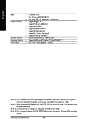
GA-P35-DS3P Motherboard - 12 - English BIOS Unique Features Bundled Software Operating System Form Factor Š 2 x 8 Mbit flash Š Use of licensed AWARD BIOS Š PnP 1.0a, DMI 2.0, SM ... second PCI Express x16 slot (PCIE_16_2) is in use, the three PCI Express x1 slots become unavailable. (Note 3) Available functions in Easytune may differ by motherboard model. (Note 4) Due to chipset limitation, Intel ICH9R RAID driver does not support Windows 2000 operating system.
GA-P35-DS3P Motherboard - 12 - English BIOS Unique Features Bundled Software Operating System Form Factor Š 2 x 8 Mbit flash Š Use of licensed AWARD BIOS Š PnP 1.0a, DMI 2.0, SM ... second PCI Express x16 slot (PCIE_16_2) is in use, the three PCI Express x1 slots become unavailable. (Note 3) Available functions in Easytune may differ by motherboard model. (Note 4) Due to chipset limitation, Intel ICH9R RAID driver does not support Windows 2000 operating system.
Manual
Page 13
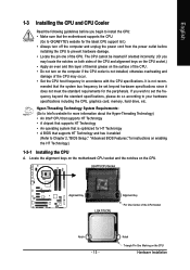
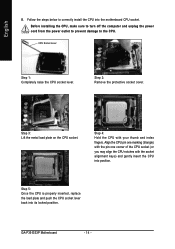
...outlet before installing the CPU to prevent hardware damage. • Locate the pin one of the CPU. Locate the alignment keys on the motherboard CPU socket and the notches on the CPU Hardware Installation If you wish to set beyond the standard specifications, please do so according to ... Installing the CPU and CPU Cooler Read the following guidelines before you begin to install the CPU: • Make sure that the motherboard supports the CPU. (Go to GIGABYTE's website for the latest CPU support list.) • Always turn on the computer if the CPU cooler is not installed, otherwise ...
...outlet before installing the CPU to prevent hardware damage. • Locate the pin one of the CPU. Locate the alignment keys on the motherboard CPU socket and the notches on the CPU Hardware Installation If you wish to set beyond the standard specifications, please do so according to ... Installing the CPU and CPU Cooler Read the following guidelines before you begin to install the CPU: • Make sure that the motherboard supports the CPU. (Go to GIGABYTE's website for the latest CPU support list.) • Always turn on the computer if the CPU cooler is not installed, otherwise ...
Manual
Page 14
Step 2: Remove the protective socket cover. GA-P35-DS3P Motherboard - 14 - CPU Socket Lever Step 1: Completely raise the CPU socket lever. Step 3: Lift the metal load plate on the CPU socket. Before installing the CPU, ... insert the CPU into position. Step 5: Once the CPU is properly inserted, replace the load plate and push the CPU socket lever back into the motherboard CPU socket. Follow the steps below to the CPU. Align the CPU pin one marking (triangle) with the pin one corner of the CPU socket...
Step 2: Remove the protective socket cover. GA-P35-DS3P Motherboard - 14 - CPU Socket Lever Step 1: Completely raise the CPU socket lever. Step 3: Lift the metal load plate on the CPU socket. Before installing the CPU, ... insert the CPU into position. Step 5: Once the CPU is properly inserted, replace the load plate and push the CPU socket lever back into the motherboard CPU socket. Follow the steps below to the CPU. Align the CPU pin one marking (triangle) with the pin one corner of the CPU socket...
Manual
Page 15
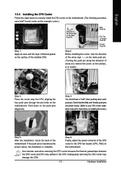
..., is to the CPU. Check that the Male and Female push pins are joined closely. (Refer to correctly install the CPU cooler on the motherboard. (The following procedure uses Intel® boxed cooler as the picture above, the installation is inserted as the example cooler.) Step 1: Apply an...CPU cooler may adhere to install.) Step 3: Place the cooler atop the CPU, aligning the four push pins through the pin holes on the motherboard. Hardware Installation If the push pin is complete. English 1-3-2 Installing the CPU Cooler Follow the steps below to your CPU cooler installation manual for...
..., is to the CPU. Check that the Male and Female push pins are joined closely. (Refer to correctly install the CPU cooler on the motherboard. (The following procedure uses Intel® boxed cooler as the picture above, the installation is inserted as the example cooler.) Step 1: Apply an...CPU cooler may adhere to install.) Step 3: Place the cooler atop the CPU, aligning the four push pins through the pin holes on the motherboard. Hardware Installation If the push pin is complete. English 1-3-2 Installing the CPU Cooler Follow the steps below to your CPU cooler installation manual for...
Manual
Page 16
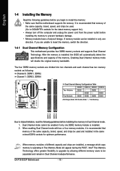
... turn off the computer and unplug the power cord from the power outlet before installing the memory in only one DDR2 memory module is installed. 2. GA-P35-DS3P Motherboard - 16 - Four Modules DS/SS DS/SS DS/SS DDRII4 - If you begin to chipset limitation, read the following : Channel 0: DDRII1, ... capacity, brand, speed, and chips be populated and remain in Dual Channel mode/performance. Dual Channel mode cannot be used . (Go to GIGABYTE's website for optimum performance. A memory module can be installed in Dual Channel mode. 1. The four DDR2 memory sockets are divided into two ...
... turn off the computer and unplug the power cord from the power outlet before installing the memory in only one DDR2 memory module is installed. 2. GA-P35-DS3P Motherboard - 16 - Four Modules DS/SS DS/SS DS/SS DDRII4 - If you begin to chipset limitation, read the following : Channel 0: DDRII1, ... capacity, brand, speed, and chips be populated and remain in Dual Channel mode/performance. Dual Channel mode cannot be used . (Go to GIGABYTE's website for optimum performance. A memory module can be installed in Dual Channel mode. 1. The four DDR2 memory sockets are divided into two ...

Manual
Page 17
... the memory, push down on the socket. Hardware Installation DDR2 DIMMs are not compatible to DDR DIMMs. Be sure to install DDR2 DIMMs on this motherboard.
... the memory, push down on the socket. Hardware Installation DDR2 DIMMs are not compatible to DDR DIMMs. Be sure to install DDR2 DIMMs on this motherboard.
Manual
Page 18
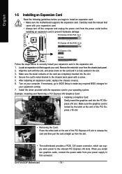
... can supply extra power to the onboard PCI Express x16 slots. When you begin to install an expansion card: • Make sure the motherboard supports the expansion card. GA-P35-DS3P Motherboard - 18 - Turn on your operating system. Make sure the metal contacts on the card until it is locked by the latch at the...
... can supply extra power to the onboard PCI Express x16 slots. When you begin to install an expansion card: • Make sure the motherboard supports the expansion card. GA-P35-DS3P Motherboard - 18 - Turn on your operating system. Make sure the metal contacts on the card until it is locked by the latch at the...
Manual
Page 19
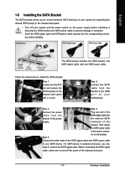
... The SATA bracket includes one SATA bracket, one SATA signal cable, and one end of the SATA signal cable and SATA power cable to your motherboard. English 1-6 Installing the SATA Bracket The SATA bracket allows you only need to connect the SATA signal cable. connector on the power supply before installing...
... The SATA bracket includes one SATA bracket, one SATA signal cable, and one end of the SATA signal cable and SATA power cable to your motherboard. English 1-6 Installing the SATA Bracket The SATA bracket allows you only need to connect the SATA signal cable. connector on the power supply before installing...
Manual
Page 20
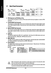
... audio. RJ-45 LAN Port The Gigabit Ethernet LAN port provides Internet connection at up to an external audio system that supports digital optical audio. GA-P35-DS3P Motherboard - 20 - Coaxial S/PDIF Out Connector This connector provides digital audio out to 1 Gbps data rate. USB Port The USB port supports the USB 2.0/1.1 specification. Use...
... audio. RJ-45 LAN Port The Gigabit Ethernet LAN port provides Internet connection at up to an external audio system that supports digital optical audio. GA-P35-DS3P Motherboard - 20 - Coaxial S/PDIF Out Connector This connector provides digital audio out to 1 Gbps data rate. USB Port The USB port supports the USB 2.0/1.1 specification. Use...
Manual
Page 22
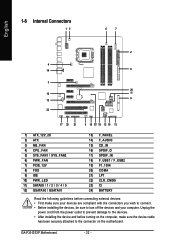
GA-P35-DS3P Motherboard - 22 - Unplug the power cord from the power outlet to prevent damage to turn off the devices and your devices are compliant with the connectors you wish to connect. • Before installing the devices, be sure to the devices. • After installing the device and before turning on the motherboard. English 1-8 Internal...
GA-P35-DS3P Motherboard - 22 - Unplug the power cord from the power outlet to prevent damage to turn off the devices and your devices are compliant with the connectors you wish to connect. • Before installing the devices, be sure to the devices. • After installing the device and before turning on the motherboard. English 1-8 Internal...
Manual
Page 23
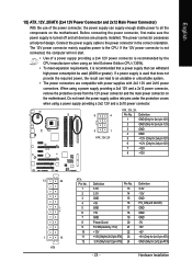
... connector in the correct orientation. Before connecting the power connector, first make sure the power supply is turned off and all the components on the motherboard. Definition 1 GND(Only for 2x4 pin 12V) 2 GND (Only for 2x4 pin 12V) 3 GND 4 GND 5 +12V (Only for 2x4 pin 12V)...supply providing a 2x4 12V and a 2x12 power connector, remove the protective covers from the 12V power connector and the main power connector on the motherboard. English 1/2) ATX_12V_2X/ATX (2x4 12V Power Connector and 2x12 Main Power Connector) With the use of a power supply providing a 2x4 12V ...
... connector in the correct orientation. Before connecting the power connector, first make sure the power supply is turned off and all the components on the motherboard. Definition 1 GND(Only for 2x4 pin 12V) 2 GND (Only for 2x4 pin 12V) 3 GND 4 GND 5 +12V (Only for 2x4 pin 12V)...supply providing a 2x4 12V and a 2x12 power connector, remove the protective covers from the 12V power connector and the main power connector on the motherboard. English 1/2) ATX_12V_2X/ATX (2x4 12V Power Connector and 2x12 Main Power Connector) With the use of a power supply providing a 2x4 12V ...
Manual
Page 24
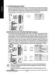
...fans are not configuration jumper blocks. Definition 1 1 GND 2 +12V 3 NC 4/5/6) CPU_FAN / SYS_FAN1 / SYS_FAN2 / PWR_FAN (Fan Headers) The motherboard has a 4-pin CPU fan header (CPU_FAN), a 4-pin system fan header (SYS_FAN2), a 3-pin power fan header (PWR_FAN),and a 3-pin ...black connector wire is the ground wire. Each fan header supplies a +12V power voltage and possesses a foolproof insertion design. GA-P35-DS3P Motherboard - 24 - The motherboard supports CPU fan speed control, which requires the use of a CPU fan with colorcoded power connector wires. Most fans are ...
...fans are not configuration jumper blocks. Definition 1 1 GND 2 +12V 3 NC 4/5/6) CPU_FAN / SYS_FAN1 / SYS_FAN2 / PWR_FAN (Fan Headers) The motherboard has a 4-pin CPU fan header (CPU_FAN), a 4-pin system fan header (SYS_FAN2), a 3-pin power fan header (PWR_FAN),and a 3-pin ...black connector wire is the ground wire. Each fan header supplies a +12V power voltage and possesses a foolproof insertion design. GA-P35-DS3P Motherboard - 24 - The motherboard supports CPU fan speed control, which requires the use of a CPU fan with colorcoded power connector wires. Most fans are ...
Manual
Page 25
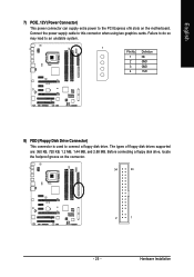
... disk drives supported are: 360 KB, 720 KB, 1.2 MB, 1.44 MB, and 2.88 MB. Before connecting a floppy disk drive, locate the foolproof groove on the motherboard. English 7) PCIE_12V (Power Connector) This power connector can supply extra power to the PCI Express x16 slots on the connector. 34 33 2 1 - 25 - Definition 1 NC...
... disk drives supported are: 360 KB, 720 KB, 1.2 MB, 1.44 MB, and 2.88 MB. Before connecting a floppy disk drive, locate the foolproof groove on the motherboard. English 7) PCIE_12V (Power Connector) This power connector can supply extra power to the PCI Express x16 slots on the connector. 34 33 2 1 - 25 - Definition 1 NC...


