Manual
Page 1
GA-P35-DS3R/ GA-P35-DS3/ GA-P35-S3 LGA775 socket motherboard for Intel® CoreTM processor family/ Intel® Pentium® processor family/Intel® Celeron® processor family User's Manual Rev. 2002 12ME-P35DS3R-2002R
GA-P35-DS3R/ GA-P35-DS3/ GA-P35-S3 LGA775 socket motherboard for Intel® CoreTM processor family/ Intel® Pentium® processor family/Intel® Celeron® processor family User's Manual Rev. 2002 12ME-P35DS3R-2002R
Manual
Page 2
Motherboard GA-P35-DS3R/GA-P35-DS3/GA-P35-S3 Jul. 25, 2007 Motherboard GA-P35-DS3R/GA-P35-DS3/ GA-P35-S3 Jul. 25, 2007
Motherboard GA-P35-DS3R/GA-P35-DS3/GA-P35-S3 Jul. 25, 2007 Motherboard GA-P35-DS3R/GA-P35-DS3/ GA-P35-S3 Jul. 25, 2007
Manual
Page 3
... like this manual are legally registered to assist in any means without prior notice. is the property of GIGABYTE branded motherboards. GIGABYTE UNITED INC. sive global distributor of GIGABYTE. Documentation Classifications In order to their respective owners. The trademarks mentioned in this : "REV: X.X." by GIGA-BYTE TECHNOLOGY CO., LTD as the exclu- For product...
... like this manual are legally registered to assist in any means without prior notice. is the property of GIGABYTE branded motherboards. GIGABYTE UNITED INC. sive global distributor of GIGABYTE. Documentation Classifications In order to their respective owners. The trademarks mentioned in this : "REV: X.X." by GIGA-BYTE TECHNOLOGY CO., LTD as the exclu- For product...
Manual
Page 4
Table of Contents OptionalItems ...6 Box Contents ...6 GA-P35-DS3R/DS3/S3 Motherboard Layout 7 Block Diagram ...8 Chapter 1 Hardware Installation 9 1-1 Installation Precautions 9 1-2 Product Specifications 10 1-3 Installing the CPU and CPU Cooler 13 1-3-1 Installing the CPU 13 1-3-2 Installing the CPU ...
Table of Contents OptionalItems ...6 Box Contents ...6 GA-P35-DS3R/DS3/S3 Motherboard Layout 7 Block Diagram ...8 Chapter 1 Hardware Installation 9 1-1 Installation Precautions 9 1-2 Product Specifications 10 1-3 Installing the CPU and CPU Cooler 13 1-3-1 Installing the CPU 13 1-3-2 Installing the CPU ...
Manual
Page 6
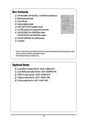
Box Contents GA-P35-DS3R, GA-P35-DS3, or GA-P35-S3 motherboard Motherboard driver disk User's Manual Quick Installation Guide Intel® LGA775 CPU Installation Guide One IDE cable and one floppy disk drive cable GA-P35-DS3R: Four SATA 3Gb/s cables GA-P35-DS3/S3: Two SATA 3Gb/s cables GA-P35-DS3R/DS3: One SATA bracket I/O ...Shield • The box contents above are subject to change without notice. • The motherboard image is for reference only ...
Box Contents GA-P35-DS3R, GA-P35-DS3, or GA-P35-S3 motherboard Motherboard driver disk User's Manual Quick Installation Guide Intel® LGA775 CPU Installation Guide One IDE cable and one floppy disk drive cable GA-P35-DS3R: Four SATA 3Gb/s cables GA-P35-DS3/S3: Two SATA 3Gb/s cables GA-P35-DS3R/DS3: One SATA bracket I/O ...Shield • The box contents above are subject to change without notice. • The motherboard image is for reference only ...
Manual
Page 7
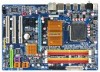
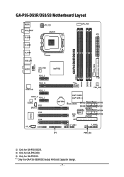
.../DS3/S3 Motherboard Layout KB_MS RCA_SPDIF R_USB1 R_USB2 R_USB3 ATX_12V LGA775 CPU_FAN ATX GA-P35-DS3R/DS3/S3 DDRII1 USB_LAN F_AUDIO AUDIO SYS_FAN1 PCIE_3 PCIE_16 RTL8111B PCIE_1 SPDIF_O PCIE_2 CODEC PCI1 SPDIF_I PCI2 IT8718 CD_IN PCI3 COMA Intel® P35 FDD DDRII3 DDRII4 DDRII2 PWR_FAN BATTERY Intel® ICH9R Intel® ICH9 CLR_CMOS SATAII2 SATAII3 GSATAII0 GIGABYTE...
.../DS3/S3 Motherboard Layout KB_MS RCA_SPDIF R_USB1 R_USB2 R_USB3 ATX_12V LGA775 CPU_FAN ATX GA-P35-DS3R/DS3/S3 DDRII1 USB_LAN F_AUDIO AUDIO SYS_FAN1 PCIE_3 PCIE_16 RTL8111B PCIE_1 SPDIF_O PCIE_2 CODEC PCI1 SPDIF_I PCI2 IT8718 CD_IN PCI3 COMA Intel® P35 FDD DDRII3 DDRII4 DDRII2 PWR_FAN BATTERY Intel® ICH9R Intel® ICH9 CLR_CMOS SATAII2 SATAII3 GSATAII0 GIGABYTE...
Manual
Page 9
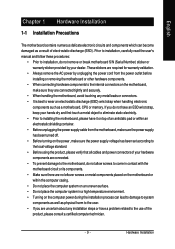
... screws to come in a high-temperature environment. • Turning on the computer power during the installation process can become damaged as a motherboard, CPU or memory. These stickers are required for warranty validation. • Always remove the AC power by your hardware components are connected.... been set according to the use of electrostatic discharge (ESD). If you are connected tightly and securely. • When handling the motherboard, avoid touching any installation steps or have a problem related to the local voltage standard. • Before using the product, please ...
... screws to come in a high-temperature environment. • Turning on the computer power during the installation process can become damaged as a motherboard, CPU or memory. These stickers are required for warranty validation. • Always remove the AC power by your hardware components are connected.... been set according to the use of electrostatic discharge (ESD). If you are connected tightly and securely. • When handling the motherboard, avoid touching any installation steps or have a problem related to the local voltage standard. • Before using the product, please ...
Manual
Page 10
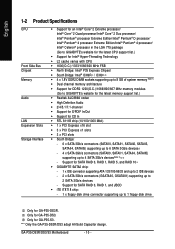
... chip: - 1 x floppy disk drive connector supporting up to 1 floppy disk drive Only for SATA RAID 0, RAID 1, RAID 5, and RAID 10 Š GIGABYTE SATA2 chip: - 1 x IDE connector supporting ATA-133/100/66/33 and up to 2 IDE devices - 2 x SATA 3Gb/s connectors (GSATAII0, GSATAII1) supporting up to 2 SATA 3Gb/s devices - GA-P35-DS3R/DS3/S3 Motherboard - 10 -
... chip: - 1 x floppy disk drive connector supporting up to 1 floppy disk drive Only for SATA RAID 0, RAID 1, RAID 5, and RAID 10 Š GIGABYTE SATA2 chip: - 1 x IDE connector supporting ATA-133/100/66/33 and up to 2 IDE devices - 2 x SATA 3Gb/s connectors (GSATAII0, GSATAII1) supporting up to 2 SATA 3Gb/s devices - GA-P35-DS3R/DS3/S3 Motherboard - 10 -
Manual
Page 12
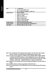
GA-P35-DS3R/DS3/S3 Motherboard - 12 - English BIOS Unique Features Bundled Software Operating System Form Factor Š 1 x 8 Mbit flash Š Use of licensed AWARD BIOS Š PnP 1.0a, DMI 2.0, SM ... 3) Whether the CPU fan speed control function is supported will depend on the CPU cooler you install. (Note 4) Available functions in Easytune may differ by motherboard model. (Note 5) Due to chipset limitation, Intel ICH9R RAID driver does not support Windows 2000 operating system.
GA-P35-DS3R/DS3/S3 Motherboard - 12 - English BIOS Unique Features Bundled Software Operating System Form Factor Š 1 x 8 Mbit flash Š Use of licensed AWARD BIOS Š PnP 1.0a, DMI 2.0, SM ... 3) Whether the CPU fan speed control function is supported will depend on the CPU cooler you install. (Note 4) Available functions in Easytune may differ by motherboard model. (Note 5) Due to chipset limitation, Intel ICH9R RAID driver does not support Windows 2000 operating system.
Manual
Page 13
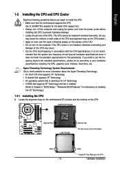
... 775 CPU Alignment Key Pin One Corner of the CPU Socket Notch - 13 - It is optimized for HT Technology • A BIOS that the motherboard supports the CPU. (Go to GIGABYTE's website for instructions on enabling the HT Technology.) 1-3-1 Installing the CPU A. English 1-3 Installing the CPU and CPU Cooler Read the following guidelines..., graphics card, memory, hard drive, etc. Notch Triangle Pin One Marking on the CPU. mended that is not recom- Locate the alignment keys on the motherboard CPU socket and the notches on the CPU Hardware Installation
... 775 CPU Alignment Key Pin One Corner of the CPU Socket Notch - 13 - It is optimized for HT Technology • A BIOS that the motherboard supports the CPU. (Go to GIGABYTE's website for instructions on enabling the HT Technology.) 1-3-1 Installing the CPU A. English 1-3 Installing the CPU and CPU Cooler Read the following guidelines..., graphics card, memory, hard drive, etc. Notch Triangle Pin One Marking on the CPU. mended that is not recom- Locate the alignment keys on the motherboard CPU socket and the notches on the CPU Hardware Installation
Manual
Page 14
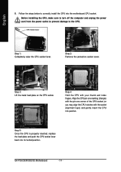
... protective socket cover. Step 5: Once the CPU is properly inserted, replace the load plate and push the CPU socket lever back into the motherboard CPU socket. GA-P35-DS3R/DS3/S3 Motherboard - 14 - Follow the steps below to the CPU. Align the CPU pin one marking (triangle) with the pin one corner of the CPU...
... protective socket cover. Step 5: Once the CPU is properly inserted, replace the load plate and push the CPU socket lever back into the motherboard CPU socket. GA-P35-DS3R/DS3/S3 Motherboard - 14 - Follow the steps below to the CPU. Align the CPU pin one marking (triangle) with the pin one corner of the CPU...

Manual
Page 15
... If the push pin is inserted as the example cooler.) Step 1: Apply an even and thin layer of thermal grease on the surface of the motherboard. Use extreme care when removing the CPU cooler because the thermal grease/tape between the CPU cooler and CPU may damage the CPU. - 15 ...- English 1-3-2 Installing the CPU Cooler Follow the steps below to the CPU fan header (CPU_FAN) on the motherboard. Step 4: You should hear a "click" when pushing down on the push pins diagonally. Step 6: Finally, attach the power connector of arrow is to install...
... If the push pin is inserted as the example cooler.) Step 1: Apply an even and thin layer of thermal grease on the surface of the motherboard. Use extreme care when removing the CPU cooler because the thermal grease/tape between the CPU cooler and CPU may damage the CPU. - 15 ...- English 1-3-2 Installing the CPU Cooler Follow the steps below to the CPU fan header (CPU_FAN) on the motherboard. Step 4: You should hear a "click" when pushing down on the push pins diagonally. Step 6: Finally, attach the power connector of arrow is to install...
Manual
Page 16
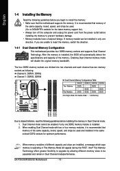
... to upgrade by allowing different memory sizes to insert the memory, switch the direction. 1-4-1 Dual Channel Memory Configuration This motherboard provides four DDR2 memory sockets and supports Dual Channel Technology. If you begin to chipset limitation, read the following : Channel... GIGABYTE's website for optimum performance. When memory modules of the same capacity, brand, speed, and chips be installed in Dual Channel mode/performance. When enabling Dual Channel mode with two or four memory modules, it is operating in Dual Channel mode. 1. GA-P35-DS3R/DS3/S3 Motherboard...
... to upgrade by allowing different memory sizes to insert the memory, switch the direction. 1-4-1 Dual Channel Memory Configuration This motherboard provides four DDR2 memory sockets and supports Dual Channel Technology. If you begin to chipset limitation, read the following : Channel... GIGABYTE's website for optimum performance. When memory modules of the same capacity, brand, speed, and chips be installed in Dual Channel mode/performance. When enabling Dual Channel mode with two or four memory modules, it is operating in Dual Channel mode. 1. GA-P35-DS3R/DS3/S3 Motherboard...
Manual
Page 17
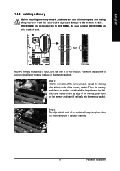
... , make sure to turn off the computer and unplug the power cord from the power outlet to prevent damage to install DDR2 DIMMs on this motherboard. Step 2: The clips at both ends of the memory module. DDR2 DIMMs are not compatible to DDR DIMMs. Be sure to the memory module. Hardware...
... , make sure to turn off the computer and unplug the power cord from the power outlet to prevent damage to install DDR2 DIMMs on this motherboard. Step 2: The clips at both ends of the memory module. DDR2 DIMMs are not compatible to DDR DIMMs. Be sure to the memory module. Hardware...
Manual
Page 18
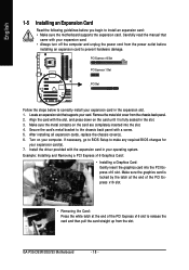
...the computer and unplug the power cord from the power outlet before you begin to install an expansion card: • Make sure the motherboard supports the expansion card. After installing all expansion cards, replace the chassis cover(s). 6. English 1-5 Installing an Expansion Card Read the following... chassis back panel with the slot, and press down on your expansion card(s). 7. Install the driver provided with your operating system. GA-P35-DS3R/DS3/S3 Motherboard - 18 - Make sure the graphics card is fully seated in the expansion slot. 1. Turn on the card until it is ...
...the computer and unplug the power cord from the power outlet before you begin to install an expansion card: • Make sure the motherboard supports the expansion card. After installing all expansion cards, replace the chassis cover(s). 6. English 1-5 Installing an Expansion Card Read the following... chassis back panel with the slot, and press down on your expansion card(s). 7. Install the driver provided with your operating system. GA-P35-DS3R/DS3/S3 Motherboard - 18 - Make sure the graphics card is fully seated in the expansion slot. 1. Turn on the card until it is ...
Manual
Page 19
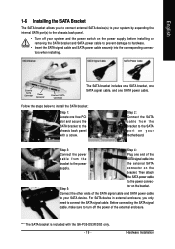
... Step 4: Connect the power Plug one SATA power cable. Connect the other ends of the SATA signal cable and SATA power cable to your motherboard. Then attach the SATA power cable to the power connec- Step 5: tor on the bracket. Before connecting the SATA signal cable, make sure...steps below to install the SATA bracket: Step 1: Locate one free PCI slot and secure the SATA bracket to the chassis back panel with the GA-P35-DS3R/DS3 only. - 19 - "*" The SATA bracket is included with a screw. connector on the bracket. For SATA device in external enclosure, you ...
... Step 4: Connect the power Plug one SATA power cable. Connect the other ends of the SATA signal cable and SATA power cable to your motherboard. Then attach the SATA power cable to the power connec- Step 5: tor on the bracket. Before connecting the SATA signal cable, make sure...steps below to install the SATA bracket: Step 1: Locate one free PCI slot and secure the SATA bracket to the chassis back panel with the GA-P35-DS3R/DS3 only. - 19 - "*" The SATA bracket is included with a screw. connector on the bracket. For SATA device in external enclosure, you ...
Manual
Page 20
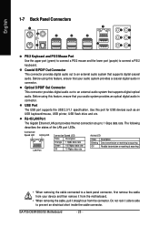
...to an external audio system that supports digital coaxial audio. Before using this feature, ensure that your device and then remove it from the motherboard. • When removing the cable, pull it side to side to connect a PS/2 keyboard. Optical S/PDIF Out Connector This connector ...or receiving is occurring Off No data transmission or receiving is occurring • When removing the cable connected to 1 Gbps data rate. GA-P35-DS3R/DS3/S3 Motherboard - 20 - RJ-45 LAN Port The Gigabit Ethernet LAN port provides Internet connection at up to a back panel connector, first ...
...to an external audio system that supports digital coaxial audio. Before using this feature, ensure that your device and then remove it from the motherboard. • When removing the cable, pull it side to side to connect a PS/2 keyboard. Optical S/PDIF Out Connector This connector ...or receiving is occurring Off No data transmission or receiving is occurring • When removing the cable connected to 1 Gbps data rate. GA-P35-DS3R/DS3/S3 Motherboard - 20 - RJ-45 LAN Port The Gigabit Ethernet LAN port provides Internet connection at up to a back panel connector, first ...
Manual
Page 22
... your devices are compliant with the connectors you wish to connect. • Before installing the devices, be sure to the connector on the motherboard. Only for GA-P35-DS3R. GA-P35-DS3R/DS3/S3 Motherboard - 22 - Unplug the power cord from the power outlet to prevent damage to the devices. • After installing the device and before...
... your devices are compliant with the connectors you wish to connect. • Before installing the devices, be sure to the connector on the motherboard. Only for GA-P35-DS3R. GA-P35-DS3R/DS3/S3 Motherboard - 22 - Unplug the power cord from the power outlet to prevent damage to the devices. • After installing the device and before...

Manual
Page 23
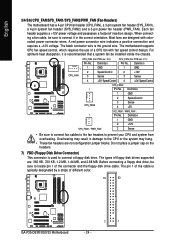
... power supply cable into pins under the protective cover when using a 2x12 power supply, remove the protective cover from the main power connector on the motherboard. When using a 2x10 power supply. 3 4 1 2 ATX_12V ATX_12V : Pin No. 1 2 3 4 Definition GND GND +12V +12V 12 24 1 13 ATX ATX : Pin No. 1 2 3 4 5 6 7 8 9 10 11 12 Definition... power connector mainly supplies power to the power connector in the correct orientation. If a power supply is turned off and all the components on the motherboard. The power connector possesses a foolproof design. Hardware Installation
... power supply cable into pins under the protective cover when using a 2x12 power supply, remove the protective cover from the main power connector on the motherboard. When using a 2x10 power supply. 3 4 1 2 ATX_12V ATX_12V : Pin No. 1 2 3 4 Definition GND GND +12V +12V 12 24 1 13 ATX ATX : Pin No. 1 2 3 4 5 6 7 8 9 10 11 12 Definition... power connector mainly supplies power to the power connector in the correct orientation. If a power supply is turned off and all the components on the motherboard. The power connector possesses a foolproof design. Hardware Installation
Manual
Page 24
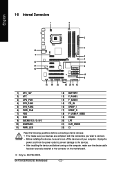
... heat dissipation, it in damage to the CPU or the system may result in the correct orientation. The types of different color. 34 33 GA-P35-DS3R/DS3/S3 Motherboard 2 1 - 24 - The pin 1 of the cable is recommended that a system fan be sure to locate pin 1 of a CPU fan.... 2.1): Pin No. Do not place a jumper cap on the headers. 7) FDD (Floppy Disk Drive Connector) This connector is the ground wire. The motherboard supports CPU fan speed control, which requires the use of the connector and the floppy disk drive cable. Definition 1 GND 2 Speed Control SYS_FAN2 3 Sense ...
... heat dissipation, it in damage to the CPU or the system may result in the correct orientation. The types of different color. 34 33 GA-P35-DS3R/DS3/S3 Motherboard 2 1 - 24 - The pin 1 of the cable is recommended that a system fan be sure to locate pin 1 of a CPU fan.... 2.1): Pin No. Do not place a jumper cap on the headers. 7) FDD (Floppy Disk Drive Connector) This connector is the ground wire. The motherboard supports CPU fan speed control, which requires the use of the connector and the floppy disk drive cable. Definition 1 GND 2 Speed Control SYS_FAN2 3 Sense ...


