Manual
Page 8
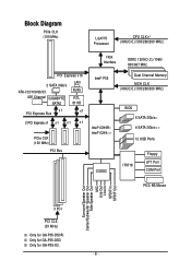
Only for GA-P35-DS3R. Block Diagram PCIe CLK (100 MHz) LGA775 Processor CPU CLK+/(400(O.C.)/333/266/200 MHz) Host Interface DDR2 1200(O.C.)/1066/ 800/667 MHz PCI Express x16 2 SATA 3Gb/s ATA-133/100/66/33 IDE Channel GIGABYTE SATA2 LAN RJ45 RTL 8111B x1 PCI Express Bus x1 3 PCI Express x1 x 1 x 1 x 1 PCIe CLK (100... Speaker Out Center/Subwoofer Speaker Out Side Speaker Out MIC Line-Out Line-In SPDIF In SPDIF Out 3 PCI PCI CLK (33 MHz) Only for GA-P35-S3. - 8 - Only for GA-P35-DS3.
Only for GA-P35-DS3R. Block Diagram PCIe CLK (100 MHz) LGA775 Processor CPU CLK+/(400(O.C.)/333/266/200 MHz) Host Interface DDR2 1200(O.C.)/1066/ 800/667 MHz PCI Express x16 2 SATA 3Gb/s ATA-133/100/66/33 IDE Channel GIGABYTE SATA2 LAN RJ45 RTL 8111B x1 PCI Express Bus x1 3 PCI Express x1 x 1 x 1 x 1 PCIe CLK (100... Speaker Out Center/Subwoofer Speaker Out Side Speaker Out MIC Line-Out Line-In SPDIF In SPDIF Out 3 PCI PCI CLK (33 MHz) Only for GA-P35-S3. - 8 - Only for GA-P35-DS3.
Manual
Page 54
... automatically set the system voltages as required. Normal Supplies the FSB voltage as required. (Default) +0.1V ~ +0.3V Increases PCIe bus voltage by 0.1V to set the CPU voltage. Normal CPU Vcore Displays the normal operating voltage of your CPU or ...~ +0.3V Increases FSB voltage by 0.1V to set PCIe voltage. Manual allows all voltage control items below to be configurable. (Default: Manual) DDR2 OverVoltage Control Allows you to to manually set the system voltages. English System Voltage Control Determines whether to set memory voltage. GA-P35-DS3R/DS3/S3 Motherboard - 54 -
... automatically set the system voltages as required. Normal Supplies the FSB voltage as required. (Default) +0.1V ~ +0.3V Increases PCIe bus voltage by 0.1V to set the CPU voltage. Normal CPU Vcore Displays the normal operating voltage of your CPU or ...~ +0.3V Increases FSB voltage by 0.1V to set PCIe voltage. Manual allows all voltage control items below to be configurable. (Default: Manual) DDR2 OverVoltage Control Allows you to to manually set the system voltages. English System Voltage Control Determines whether to set memory voltage. GA-P35-DS3R/DS3/S3 Motherboard - 54 -
Manual
Page 82
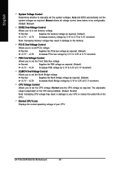
... . Figure 2 In the main screen of Windows operating system for a message which says "Press to enter the GIGABYTE SATA2 RAID BIOS utility. GA-P35-DS3R/DS3/S3 Motherboard - 82 - http://www.gigabyte.com.tw HDD0 : HDD1 : ST3120026AS ST3120026AS 120 GB Non-RAID 120 GB Non-RAID ODD0 : DVDROM GO-D1600B... key to highlight through choices in RAID BIOS Enter the RAID BIOS setup utility to see detailed information about the selected hard drive. PCIE-to enter RAID Setup Utility ... Press + to enter RAID Setup Utility" (Figure 2). After the POST memory test begins and before...
... . Figure 2 In the main screen of Windows operating system for a message which says "Press to enter the GIGABYTE SATA2 RAID BIOS utility. GA-P35-DS3R/DS3/S3 Motherboard - 82 - http://www.gigabyte.com.tw HDD0 : HDD1 : ST3120026AS ST3120026AS 120 GB Non-RAID 120 GB Non-RAID ODD0 : DVDROM GO-D1600B... key to highlight through choices in RAID BIOS Enter the RAID BIOS setup utility to see detailed information about the selected hard drive. PCIE-to enter RAID Setup Utility ... Press + to enter RAID Setup Utility" (Figure 2). After the POST memory test begins and before...
Manual
Page 84
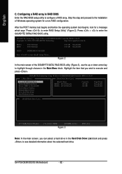
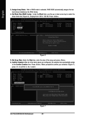
.... 6. When prompted to confirm your selection (Figure 7), press to confirm or to the Confirm Creation item. GIGABYTE Technology Corp. The following are configured, the selection bar automatically jumps to abort. Press . Press . Set ...typical values: RAID 0-128KB [KL]-Switch RAID Block Size [ENTER]-Next Figure 6 [ESC]-Abort 5. GIGABYTE Technology Corp. PCIE-to seperate RAID members. PCIE-to-SATAII/IDE RAID Controller BIOSv1.06.59 [ Create New RAID ] [ Hard Disk Drive List...Delete Number Figure 7 [ENTER]-Next [ESC]-Abort GA-P35-DS3R/DS3/S3 Motherboard - 84 - English 3.
.... 6. When prompted to confirm your selection (Figure 7), press to confirm or to the Confirm Creation item. GIGABYTE Technology Corp. The following are configured, the selection bar automatically jumps to abort. Press . Press . Set ...typical values: RAID 0-128KB [KL]-Switch RAID Block Size [ENTER]-Next Figure 6 [ESC]-Abort 5. GIGABYTE Technology Corp. PCIE-to seperate RAID members. PCIE-to-SATAII/IDE RAID Controller BIOSv1.06.59 [ Create New RAID ] [ Hard Disk Drive List...Delete Number Figure 7 [ENTER]-Next [ESC]-Abort GA-P35-DS3R/DS3/S3 Motherboard - 84 - English 3.
Manual
Page 86
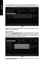
...to the RAID Disk Drive List block. When prompted to confirm your settings before exiting the RAID BIOS utility, then press (Figure 10). PCIE-to-SATAII/IDE RAID Controller BIOSv1.06.59 [ Main Menu ] [ Hard Disk Drive List ] Create RAID Disk Drive Delete RAID Disk...Level Capacity Status 0-Stripe 240 GB Normal Members(HDDx) 01 [KL]-Select RAID [SPACE]-Mark Delete [DEL]-Confirm Figure 11 GA-P35-DS3R/DS3/S3 Motherboard - 86 - [ESC]-Abort GIGABYTE Technology Corp. PCIE-to-SATAII/IDE RAID Controller BIOSv1.06.59 [ Main Menu ] [ Hard Disk Drive List ] Create RAID Disk Drive ...
...to the RAID Disk Drive List block. When prompted to confirm your settings before exiting the RAID BIOS utility, then press (Figure 10). PCIE-to-SATAII/IDE RAID Controller BIOSv1.06.59 [ Main Menu ] [ Hard Disk Drive List ] Create RAID Disk Drive Delete RAID Disk...Level Capacity Status 0-Stripe 240 GB Normal Members(HDDx) 01 [KL]-Select RAID [SPACE]-Mark Delete [DEL]-Confirm Figure 11 GA-P35-DS3R/DS3/S3 Motherboard - 86 - [ESC]-Abort GIGABYTE Technology Corp. PCIE-to-SATAII/IDE RAID Controller BIOSv1.06.59 [ Main Menu ] [ Hard Disk Drive List ] Create RAID Disk Drive ...


