Manual
Page 3
Changes to use GIGABYTE's unique features, read or download the information on/from the Support\Motherboard\Technology Guide page on your motherboard revision before updating motherboard BIOS, drivers, or when looking for technical information. For example, "REV: 1.0" means the revision of the ...number on our website. Example: The trademarks mentioned in this product, GIGABYTE provides the following types of GIGABYTE. No part of this manual may be made by any form or by GIGABYTE without GIGABYTE's prior written permission. Copyright © 2008 GIGA-BYTE TECHNOLOGY CO...
Changes to use GIGABYTE's unique features, read or download the information on/from the Support\Motherboard\Technology Guide page on your motherboard revision before updating motherboard BIOS, drivers, or when looking for technical information. For example, "REV: 1.0" means the revision of the ...number on our website. Example: The trademarks mentioned in this product, GIGABYTE provides the following types of GIGABYTE. No part of this manual may be made by any form or by GIGABYTE without GIGABYTE's prior written permission. Copyright © 2008 GIGA-BYTE TECHNOLOGY CO...
Manual
Page 4
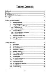
Table of Contents Box Contents ...6 OptionalItems ...6 GA-P31-ES3G Motherboard Layout 7 Block Diagram ...8 Chapter 1 Hardware Installation 9 1-1 Installation Precautions 9 1-2 Product Specifications 10 1-3 Installing the CPU and CPU Cooler 13... Memory 17 1-5 Installing an Expansion Card 18 1-6 Back Panel Connectors 19 1-7 Internal Connectors 21 Chapter 2 BIOS Setup 31 2-1 Startup Screen 32 2-2 The Main Menu 33 2-3 Standard CMOS Features 35 2-4 Advanced BIOS Features 37 2-5 IntegratedPeripherals 39 2-6 Power Management Setup 42 2-7 PnP/PCI Configurations 44 2-8 PC Health Status ...
Table of Contents Box Contents ...6 OptionalItems ...6 GA-P31-ES3G Motherboard Layout 7 Block Diagram ...8 Chapter 1 Hardware Installation 9 1-1 Installation Precautions 9 1-2 Product Specifications 10 1-3 Installing the CPU and CPU Cooler 13... Memory 17 1-5 Installing an Expansion Card 18 1-6 Back Panel Connectors 19 1-7 Internal Connectors 21 Chapter 2 BIOS Setup 31 2-1 Startup Screen 32 2-2 The Main Menu 33 2-3 Standard CMOS Features 35 2-4 Advanced BIOS Features 37 2-5 IntegratedPeripherals 39 2-6 Power Management Setup 42 2-7 PnP/PCI Configurations 44 2-8 PC Health Status ...

Manual
Page 5
... 54 3-3 Technical Manuals 54 3-4 Contact ...55 3-5 System ...55 3-6 Download Center 56 Chapter 4 Unique Features 57 4-1 Xpress Recovery2 57 4-2 BIOS Update Utilities 62 4-2-1 Updating the BIOS with the Q-Flash Utility 62 4-2-2 Updating the BIOS with the @BIOS Utility 65 4-3 EasyTune 5 Pro 66 4-4 Easy Energy Saver 67 Chapter 5 Appendix ...69 5-1 ConfiguringAudio Input and Output 69 5-1-1 Configuring...
... 54 3-3 Technical Manuals 54 3-4 Contact ...55 3-5 System ...55 3-6 Download Center 56 Chapter 4 Unique Features 57 4-1 Xpress Recovery2 57 4-2 BIOS Update Utilities 62 4-2-1 Updating the BIOS with the Q-Flash Utility 62 4-2-2 Updating the BIOS with the @BIOS Utility 65 4-3 EasyTune 5 Pro 66 4-4 Easy Energy Saver 67 Chapter 5 Appendix ...69 5-1 ConfiguringAudio Input and Output 69 5-1-1 Configuring...
Manual
Page 8
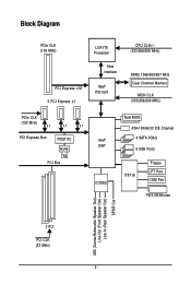
Block Diagram PCIe CLK (100 MHz) LGA775 Processor Host Interface PCI Express x16 3 PCI Express x1 Intel® P31/G31 CPU CLK+/(333/266/200 MHz) DDR2 1066/800/667 MHz Dual Channel Memory MCH CLK (333/266/200 MHz) PCIe CLK (100 MHz) x1 x1 x1 PCI Express Bus RTL8111C RJ45 LAN PCI Bus Intel® ICH7 CODEC Dual BIOS ATA-100/66/33 IDE Channel 4 SATA 3Gb/s 8 USB Ports IT8718 Floppy LPT Port COM Port PS/2 KB/Mouse MIC (Center/Subwoofer Speaker Out) Line-Out (Front Speaker Out) Line-In (Rear Speaker Out) SPDIF Out 3 PCI PCI CLK (33 MHz) - 8 -
Block Diagram PCIe CLK (100 MHz) LGA775 Processor Host Interface PCI Express x16 3 PCI Express x1 Intel® P31/G31 CPU CLK+/(333/266/200 MHz) DDR2 1066/800/667 MHz Dual Channel Memory MCH CLK (333/266/200 MHz) PCIe CLK (100 MHz) x1 x1 x1 PCI Express Bus RTL8111C RJ45 LAN PCI Bus Intel® ICH7 CODEC Dual BIOS ATA-100/66/33 IDE Channel 4 SATA 3Gb/s 8 USB Ports IT8718 Floppy LPT Port COM Port PS/2 KB/Mouse MIC (Center/Subwoofer Speaker Out) Line-Out (Front Speaker Out) Line-In (Rear Speaker Out) SPDIF Out 3 PCI PCI CLK (33 MHz) - 8 -
Manual
Page 11
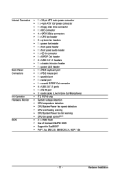
... detection Š CPU/System/Power fan speed detection Š CPU overheating warning Š CPU/System/Power fan fail warning Š CPU fan speed control(Note 3) BIOS Š 2 x 4 Mbit flash Š Use of licensed AWARD BIOS Š Support for DualBIOSTM Š PnP 1.0a, DMI 2.0, SM...
... detection Š CPU/System/Power fan speed detection Š CPU overheating warning Š CPU/System/Power fan fail warning Š CPU fan speed control(Note 3) BIOS Š 2 x 4 Mbit flash Š Use of licensed AWARD BIOS Š Support for DualBIOSTM Š PnP 1.0a, DMI 2.0, SM...
Manual
Page 12
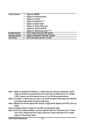
... Center Š Support for Q-Flash Š Support for EasyTune (Note 4) Š Support for Xpress Install Š Support for Xpress Recovery2 Š Support for Virtual Dual BIOS Š Support for Easy Energy Saver (Note 5) Š Norton Internet Security (OEM version) Š Support for Microsoft® Windows® Vista/XP Š ATX Form... and enable the multi-channel audio feature through the audio driver. (Note 3) Whether the CPU fan speed control function is less than the stated amount. GA-P31-ES3G Motherboard - 12 - For example, 4 GB of memory is reserved for Easy Energy Saver.
... Center Š Support for Q-Flash Š Support for EasyTune (Note 4) Š Support for Xpress Install Š Support for Xpress Recovery2 Š Support for Virtual Dual BIOS Š Support for Easy Energy Saver (Note 5) Š Norton Internet Security (OEM version) Š Support for Microsoft® Windows® Vista/XP Š ATX Form... and enable the multi-channel audio feature through the audio driver. (Note 3) Whether the CPU fan speed control function is less than the stated amount. GA-P31-ES3G Motherboard - 12 - For example, 4 GB of memory is reserved for Easy Energy Saver.
Manual
Page 16
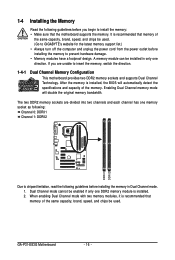
... can be enabled if only one DDR2 memory module is installed, the BIOS will double the original memory bandwidth. Dual Channel mode cannot be installed in Dual Channel mode. 1. GA-P31-ES3G Motherboard - 16 - When enabling Dual Channel mode with two memory modules..., it is recommended that memory of the same capacity, brand, speed, and chips be used . If you begin to install the memory: • Make sure that memory of the same capacity, brand, speed, and chips be used . (Go to GIGABYTE...
... can be enabled if only one DDR2 memory module is installed, the BIOS will double the original memory bandwidth. Dual Channel mode cannot be installed in Dual Channel mode. 1. GA-P31-ES3G Motherboard - 16 - When enabling Dual Channel mode with two memory modules..., it is recommended that memory of the same capacity, brand, speed, and chips be used . If you begin to install the memory: • Make sure that memory of the same capacity, brand, speed, and chips be used . (Go to GIGABYTE...
Manual
Page 18
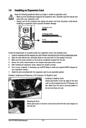
.... Turn on the card until it is fully inserted into the slot. 4. Make sure the card is securely seated in the expansion slot. 1. GA-P31-ES3G Motherboard - 18 - Locate an expansion slot that came with the slot, and press down on the slot and then lift the card straight out ...from the chassis back panel. 2. Secure the card's metal bracket to make any required BIOS changes for your computer. Install the driver provided with a screw. 5. If necessary, go to BIOS Setup to the chassis back panel with the expansion card in the slot. 3. Align the card with...
.... Turn on the card until it is fully inserted into the slot. 4. Make sure the card is securely seated in the expansion slot. 1. GA-P31-ES3G Motherboard - 18 - Locate an expansion slot that came with the slot, and press down on the slot and then lift the card straight out ...from the chassis back panel. 2. Secure the card's metal bracket to make any required BIOS changes for your computer. Install the driver provided with a screw. 5. If necessary, go to BIOS Setup to the chassis back panel with the expansion card in the slot. 3. Align the card with...
Manual
Page 26
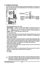
... pins before connecting the cables. If a problem is detected, the BIOS may configure the way to turn off when the system is off your chassis front panel module to indicate the problem. GA-P31-ES3G Motherboard - 26 - When connecting your system using the power switch ...(refer to Chapter 2, "BIOS Setup," "Power Management Setup," for information about beep codes. • HD (IDE Hard...
... pins before connecting the cables. If a problem is detected, the BIOS may configure the way to turn off when the system is off your chassis front panel module to indicate the problem. GA-P31-ES3G Motherboard - 26 - When connecting your system using the power switch ...(refer to Chapter 2, "BIOS Setup," "Power Management Setup," for information about beep codes. • HD (IDE Hard...
Manual
Page 28
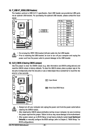
...) and reset the CMOS values to touch the two pins for BIOS configurations). GA-P31-ES3G Motherboard - 28 - Each USB header can provide two USB ports via an optional USB bracket. For purchasing the optional USB bracket, please contact the local ... the jumper cap from the jumper. Failure to do so may cause damage to the motherboard. • After system restart, go to BIOS Setup to load factory defaults (select Load Optimized Defaults) or manually configure the BIOS settings (refer to USB 2.0/1.1 specification. 14) F_USB1/F_USB2 (USB Headers) The headers conform to Chapter...
...) and reset the CMOS values to touch the two pins for BIOS configurations). GA-P31-ES3G Motherboard - 28 - Each USB header can provide two USB ports via an optional USB bracket. For purchasing the optional USB bracket, please contact the local ... the jumper cap from the jumper. Failure to do so may cause damage to the motherboard. • After system restart, go to BIOS Setup to load factory defaults (select Load Optimized Defaults) or manually configure the BIOS settings (refer to USB 2.0/1.1 specification. 14) F_USB1/F_USB2 (USB Headers) The headers conform to Chapter...
Manual
Page 29
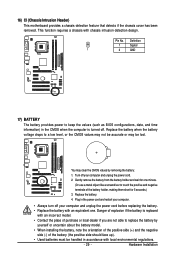
... feature that detects if the chassis cover has been removed. Definition 1 Signal 1 2 GND 17) BATTERY The battery provides power to keep the values (such as BIOS configurations, date, and time information) in the power cord and restart your computer. • Always turn off your computer and unplug the power cord before...
... feature that detects if the chassis cover has been removed. Definition 1 Signal 1 2 GND 17) BATTERY The battery provides power to keep the values (such as BIOS configurations, date, and time information) in the power cord and restart your computer. • Always turn off your computer and unplug the power cord before...

Manual
Page 31
... 5, "Troubleshooting," for how to clear the CMOS values.) - 31 - To upgrade the BIOS, use either the GIGABYTE Q-Flash or @BIOS utility. • Q-Flash allows the user to quickly and easily upgrade or back up BIOS without entering the operating system. • @BIOS is a Windows-based utility that allows the user to modify basic system configuration...
... 5, "Troubleshooting," for how to clear the CMOS values.) - 31 - To upgrade the BIOS, use either the GIGABYTE Q-Flash or @BIOS utility. • Q-Flash allows the user to quickly and easily upgrade or back up BIOS without entering the operating system. • @BIOS is a Windows-based utility that allows the user to modify basic system configuration...
Manual
Page 32
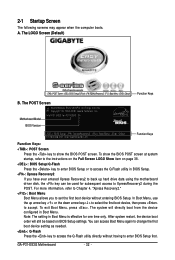
... is effective for subsequent access to accept. To exit Boot Menu, press . The system will still be used for one time only. GA-P31-ES3G Motherboard - 32 - The POST Screen Award Modular BIOS v6.00PG, An Energy Star Ally Copyright (C) 1984-2008, Award Software, Inc. Note: The setting in Boot Menu. You can be...
... is effective for subsequent access to accept. To exit Boot Menu, press . The system will still be used for one time only. GA-P31-ES3G Motherboard - 32 - The POST Screen Award Modular BIOS v6.00PG, An Energy Star Ally Copyright (C) 1984-2008, Award Software, Inc. Note: The setting in Boot Menu. You can be...
Manual
Page 33
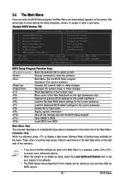
... Exit Setup Exit Without Saving ESC: Quit F8: Q-Flash KLJI: Select Item F10: Save & Exit Setup F11: Save CMOS to BIOS F12: Load CMOS from BIOS Main Menu Help The onscreen description of a highlighted setup option is not stable as shown below) appears on the screen. Press to ... function keys available for the current submenus Access the Q-Flash utility Display system information Save all the changes and exit the BIOS Setup program Save CMOS to BIOS Load CMOS from BIOS Time, Date, Hard Disk Type... 2-2 The Main Menu Once you want in the Main Menu or a submenu, press...
... Exit Setup Exit Without Saving ESC: Quit F8: Q-Flash KLJI: Select Item F10: Save & Exit Setup F11: Save CMOS to BIOS F12: Load CMOS from BIOS Main Menu Help The onscreen description of a highlighted setup option is not stable as shown below) appears on the screen. Press to ... function keys available for the current submenus Access the Q-Flash utility Display system information Save all the changes and exit the BIOS Setup program Save CMOS to BIOS Load CMOS from BIOS Time, Date, Hard Disk Type... 2-2 The Main Menu Once you want in the Main Menu or a submenu, press...
Manual
Page 34
...system voltage and fan speed, etc. „ MB Intelligent Tweaker(M.I.T.) Use this menu to configure all changes and the previous settings remain in BIOS Setup. „ Set User Password Change, set , or disable password. First select the profile you wish to load, then press to ...or disable password. First enter the profile name (to erase the default profile name, use this task.) GA-P31-ES3G Motherboard - 34 - „ The Functions of your system becomes unstable and you have loaded the BIOS default settings, you can create up to 8 profiles (Profile 1-8) and name each profile.
...system voltage and fan speed, etc. „ MB Intelligent Tweaker(M.I.T.) Use this menu to configure all changes and the previous settings remain in BIOS Setup. „ Set User Password Change, set , or disable password. First select the profile you wish to load, then press to ...or disable password. First enter the profile name (to erase the default profile name, use this task.) GA-P31-ES3G Motherboard - 34 - „ The Functions of your system becomes unstable and you have loaded the BIOS default settings, you can create up to 8 profiles (Profile 1-8) and name each profile.

Manual
Page 35
... up arrow or down arrow key to CHS. Options are : Auto (default), Large. - 35 - Options are : Auto (default), CHS, LBA, Large. BIOS Setup The date format is 13:0:0. IDE Channel 0 Master/Slave IDE HDD Auto-Detection Press to autodetect the parameters of the hard drive when the...Sets the hard drive access mode. Extended IDE Drive Configure your IDE/SATA devices by using one of the two methods below : • Auto Lets BIOS automatically detect IDE/SATA devices during the POST. (Default) • None If no IDE/SATA devices are used , set the time. For example, ...
... up arrow or down arrow key to CHS. Options are : Auto (default), Large. - 35 - Options are : Auto (default), CHS, LBA, Large. BIOS Setup The date format is 13:0:0. IDE Channel 0 Master/Slave IDE HDD Auto-Detection Press to autodetect the parameters of the hard drive when the...Sets the hard drive access mode. Extended IDE Drive Configure your IDE/SATA devices by using one of the two methods below : • Auto Lets BIOS automatically detect IDE/SATA devices during the POST. (Default) • None If no IDE/SATA devices are used , set the time. For example, ...
Manual
Page 36
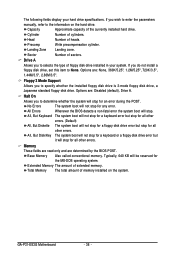
...installed on the hard drive. Cylinder Number of heads. Head Number of cylinders. Landing Zone Landing zone. All Errors Whenever the BIOS detects a non-fatal error the system boot will not stop for an error during the POST. Memory These fields are read-only...44M/3.5", 2.88M/3.5". Options are determined by the BIOS POST. Options are: Disabled (default), Drive A. The following fields display your system. All, But Disk/Key The system boot will not stop for a keyboard or a floppy disk drive error but stop . GA-P31-ES3G Motherboard - 36 - Sector Number of extended ...
...installed on the hard drive. Cylinder Number of heads. Head Number of cylinders. Landing Zone Landing zone. All Errors Whenever the BIOS detects a non-fatal error the system boot will not stop for an error during the POST. Memory These fields are read-only...44M/3.5", 2.88M/3.5". Options are determined by the BIOS POST. Options are: Disabled (default), Drive A. The following fields display your system. All, But Disk/Key The system boot will not stop for a keyboard or a floppy disk drive error but stop . GA-P31-ES3G Motherboard - 36 - Sector Number of extended ...
Manual
Page 37
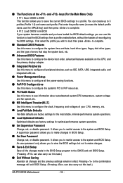
...-ZIP, USB-CDROM, USB-HDD, LAN, Disabled. HDD S.M.A.R.T. For more information about Intel CPUs' unique features, please visit Intel's website. - 37 - BIOS Setup First/Second/Third Boot Device Specifies the boot order from the installed hard drives. Use the up or down arrow key to select a hard... (or ) to exit this item, set the password(s) under the Set Supervisor/User Password item in the BIOS Main Menu. Setup A password is only required for entering the BIOS Setup program. Password Check Specifies whether a password is required every time the system boots, or only when you...
...-ZIP, USB-CDROM, USB-HDD, LAN, Disabled. HDD S.M.A.R.T. For more information about Intel CPUs' unique features, please visit Intel's website. - 37 - BIOS Setup First/Second/Third Boot Device Specifies the boot order from the installed hard drives. Use the up or down arrow key to select a hard... (or ) to exit this item, set the password(s) under the Set Supervisor/User Password item in the BIOS Main Menu. Setup A password is only required for entering the BIOS Setup program. Password Check Specifies whether a password is required every time the system boots, or only when you...
Manual
Page 39
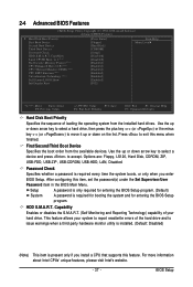
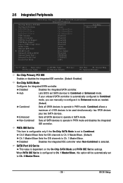
... to Combined mode, you can manually re-configure it to Enhanced mode as needed. (Default) Combined Sets all SATA devices to operate in SATA mode. BIOS Setup If your onboard SATA controller is dependent on the On-Chip SATA Mode and PATA IDE Set to operate in PATA mode. Disabled Disables... devices to Ch. 1 Master/Slave, this option will be used simultaneously: two PATA devices plus two SATA devices. PATA IDE Set to Combined. Auto Lets BIOS set to This item is configurable only if the On-Chip SATA Mode is selected. When PATA IDE Set to is configured to Combined or...
... to Combined mode, you can manually re-configure it to Enhanced mode as needed. (Default) Combined Sets all SATA devices to operate in SATA mode. BIOS Setup If your onboard SATA controller is dependent on the On-Chip SATA Mode and PATA IDE Set to operate in PATA mode. Disabled Disables... devices to Ch. 1 Master/Slave, this option will be used simultaneously: two PATA devices plus two SATA devices. PATA IDE Set to Combined. Auto Lets BIOS set to This item is configurable only if the On-Chip SATA Mode is selected. When PATA IDE Set to is configured to Combined or...
Manual
Page 41
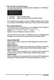
... on Part 1-2. Parallel Port Mode Selects an operating mode for the onboard parallel (LPT) port. When LAN Cable Is Functioning Normally... When a Cable Problem Occurs... BIOS Setup If no cable problem is the approximate length of the attached LAN cable. Onboard Parallel Port Enables or disables the onboard parallel port (LPT...
... on Part 1-2. Parallel Port Mode Selects an operating mode for the onboard parallel (LPT) port. When LAN Cable Is Functioning Normally... When a Cable Problem Occurs... BIOS Setup If no cable problem is the approximate length of the attached LAN cable. Onboard Parallel Port Enables or disables the onboard parallel port (LPT...


