Manual
Page 1
GA-P31-ES3G LGA775 socket motherboard for Intel® CoreTM processor family/ Intel® Pentium® processor family/Intel® Celeron® processor family User's Manual Rev. 1101 12ME-P31ES3G-1101R
GA-P31-ES3G LGA775 socket motherboard for Intel® CoreTM processor family/ Intel® Pentium® processor family/Intel® Celeron® processor family User's Manual Rev. 1101 12ME-P31ES3G-1101R
Manual
Page 2
Motherboard GA-P31-ES3G Jul. 24, 2008 Motherboard GA-P31-ES3G Jul. 24, 2008
Motherboard GA-P31-ES3G Jul. 24, 2008 Motherboard GA-P31-ES3G Jul. 24, 2008
Manual
Page 4
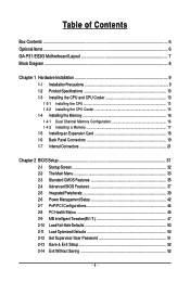
Table of Contents Box Contents ...6 OptionalItems ...6 GA-P31-ES3G Motherboard Layout 7 Block Diagram ...8 Chapter 1 Hardware Installation 9 1-1 Installation Precautions 9 1-2 Product Specifications 10 1-3 Installing the CPU and CPU Cooler 13 1-3-1 Installing the CPU 13 1-3-2 Installing the ...
Table of Contents Box Contents ...6 OptionalItems ...6 GA-P31-ES3G Motherboard Layout 7 Block Diagram ...8 Chapter 1 Hardware Installation 9 1-1 Installation Precautions 9 1-2 Product Specifications 10 1-3 Installing the CPU and CPU Cooler 13 1-3-1 Installing the CPU 13 1-3-2 Installing the ...
Manual
Page 6
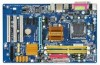
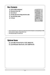
Optional Items 2-port USB 2.0 bracket (Part No. 12CR1-1UB030-51R) 2-port SATA power cable (Part No. 12CF1-2SERPW-01R) - 6 - The box contents are for reference only. Box Contents GA-P31-ES3G motherboard Motherboard driver disk User's Manual One IDE cable and one floppy disk drive cable Two SATA 3Gb/s cables I/O Shield • The box contents above are subject to change without notice. • The motherboard image is for reference only and the actual items shall depend on product package you obtain.
Optional Items 2-port USB 2.0 bracket (Part No. 12CR1-1UB030-51R) 2-port SATA power cable (Part No. 12CF1-2SERPW-01R) - 6 - The box contents are for reference only. Box Contents GA-P31-ES3G motherboard Motherboard driver disk User's Manual One IDE cable and one floppy disk drive cable Two SATA 3Gb/s cables I/O Shield • The box contents above are subject to change without notice. • The motherboard image is for reference only and the actual items shall depend on product package you obtain.
Manual
Page 7
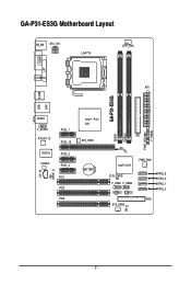
GA-P31-ES3G Motherboard Layout KB_MS ATX_12V LGA775 CPU_FAN COMA LPT COAXIAL ATX GA-P31-ES3G USB R_USB LAN AUDIO F_AUDIO RTL8111C IT8718 CODEC PCIE_1 PCIE_16 PCIE_2 PCIE_3 CD_IN SPDIF_O PCI1 PCI2 PCI3 PWR_LED F_PANEL Intel® P31/ G31 IDE SYS_FAN1 DDRII1 DDRII2 BATTERY Intel® ICH7 PWR_FAN CLR_CMOS F_USB1 F_USB2 M_BIOS B_BIOS SYS_FAN2 CI SATA2_3 SATA2_2 SATA2_1 SATA2_0 FDD - 7 -
GA-P31-ES3G Motherboard Layout KB_MS ATX_12V LGA775 CPU_FAN COMA LPT COAXIAL ATX GA-P31-ES3G USB R_USB LAN AUDIO F_AUDIO RTL8111C IT8718 CODEC PCIE_1 PCIE_16 PCIE_2 PCIE_3 CD_IN SPDIF_O PCI1 PCI2 PCI3 PWR_LED F_PANEL Intel® P31/ G31 IDE SYS_FAN1 DDRII1 DDRII2 BATTERY Intel® ICH7 PWR_FAN CLR_CMOS F_USB1 F_USB2 M_BIOS B_BIOS SYS_FAN2 CI SATA2_3 SATA2_2 SATA2_1 SATA2_0 FDD - 7 -
Manual
Page 8
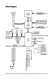
Block Diagram PCIe CLK (100 MHz) LGA775 Processor Host Interface PCI Express x16 3 PCI Express x1 Intel® P31/G31 CPU CLK+/(333/266/200 MHz) DDR2 1066/800/667 MHz Dual Channel Memory MCH CLK (333/266/200 MHz) PCIe CLK (100 MHz) x1 x1 x1 PCI Express Bus RTL8111C RJ45 LAN PCI Bus Intel® ICH7 CODEC Dual BIOS ATA-100/66/33 IDE Channel 4 SATA 3Gb/s 8 USB Ports IT8718 Floppy LPT Port COM Port PS/2 KB/Mouse MIC (Center/Subwoofer Speaker Out) Line-Out (Front Speaker Out) Line-In (Rear Speaker Out) SPDIF Out 3 PCI PCI CLK (33 MHz) - 8 -
Block Diagram PCIe CLK (100 MHz) LGA775 Processor Host Interface PCI Express x16 3 PCI Express x1 Intel® P31/G31 CPU CLK+/(333/266/200 MHz) DDR2 1066/800/667 MHz Dual Channel Memory MCH CLK (333/266/200 MHz) PCIe CLK (100 MHz) x1 x1 x1 PCI Express Bus RTL8111C RJ45 LAN PCI Bus Intel® ICH7 CODEC Dual BIOS ATA-100/66/33 IDE Channel 4 SATA 3Gb/s 8 USB Ports IT8718 Floppy LPT Port COM Port PS/2 KB/Mouse MIC (Center/Subwoofer Speaker Out) Line-Out (Front Speaker Out) Line-In (Rear Speaker Out) SPDIF Out 3 PCI PCI CLK (33 MHz) - 8 -
Manual
Page 10
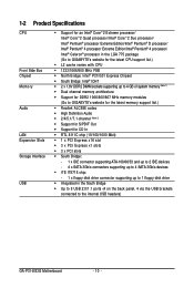
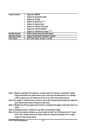
.../Intel® Pentium® 4 processor/ Intel® Celeron® processor in the LGA 775 package (Go to GIGABYTE's website for the latest CPU support list.) Š L2 cache varies with CPU Š 1333/1066/800 MHz FSB &#...memory (Note 1) Š Dual channel memory architecture Š Support for DDR2 1066/800/667 MHz memory modules (Go to GIGABYTE's website for the latest memory support list.) Š Realtek ALC888 codec Š High Definition Audio Š 2/4/5.1/7.1-channel (Note ... the back panel, 4 via the USB brackets connected to the internal USB headers) GA-P31-ES3G Motherboard - 10 -
.../Intel® Pentium® 4 processor/ Intel® Celeron® processor in the LGA 775 package (Go to GIGABYTE's website for the latest CPU support list.) Š L2 cache varies with CPU Š 1333/1066/800 MHz FSB &#...memory (Note 1) Š Dual channel memory architecture Š Support for DDR2 1066/800/667 MHz memory modules (Go to GIGABYTE's website for the latest memory support list.) Š Realtek ALC888 codec Š High Definition Audio Š 2/4/5.1/7.1-channel (Note ... the back panel, 4 via the USB brackets connected to the internal USB headers) GA-P31-ES3G Motherboard - 10 -
Manual
Page 12
... Š Support for Virtual Dual BIOS Š Support for Easy Energy Saver (Note 5) Š Norton Internet Security (OEM version) Š Support for Easy Energy Saver. GA-P31-ES3G Motherboard - 12 -
... Š Support for Virtual Dual BIOS Š Support for Easy Energy Saver (Note 5) Š Norton Internet Security (OEM version) Š Support for Easy Energy Saver. GA-P31-ES3G Motherboard - 12 -
Manual
Page 14
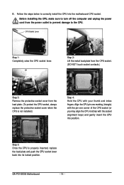
... protective socket cover when the CPU is properly inserted, replace the load plate and push the CPU socket lever back into the motherboard CPU socket. GA-P31-ES3G Motherboard - 14 - Step 2: Lift the metal load plate from the CPU socket. (DO NOT touch socket contacts.) Step 3: Remove the protective socket cover from the...
... protective socket cover when the CPU is properly inserted, replace the load plate and push the CPU socket lever back into the motherboard CPU socket. GA-P31-ES3G Motherboard - 14 - Step 2: Lift the metal load plate from the CPU socket. (DO NOT touch socket contacts.) Step 3: Remove the protective socket cover from the...
Manual
Page 16
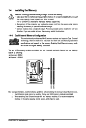
If you begin to install the memory: • Make sure that memory of the same capacity, brand, speed, and chips be used . (Go to GIGABYTE's website for the latest memory support list.) • Always turn off the computer and unplug the power cord from the power outlet before installing the ... Dual Channel memory mode will automatically detect the specifications and capacity of the same capacity, brand, speed, and chips be installed in Dual Channel mode. 1. GA-P31-ES3G Motherboard - 16 - A memory module can be used . It is installed. 2.
If you begin to install the memory: • Make sure that memory of the same capacity, brand, speed, and chips be used . (Go to GIGABYTE's website for the latest memory support list.) • Always turn off the computer and unplug the power cord from the power outlet before installing the ... Dual Channel memory mode will automatically detect the specifications and capacity of the same capacity, brand, speed, and chips be installed in Dual Channel mode. 1. GA-P31-ES3G Motherboard - 16 - A memory module can be used . It is installed. 2.
Manual
Page 18
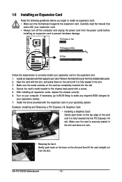
... steps below to correctly install your expansion card(s). 7. 1-5 Installing an Expansion Card Read the following guidelines before installing an expansion card to prevent hardware damage. GA-P31-ES3G Motherboard - 18 -
... steps below to correctly install your expansion card(s). 7. 1-5 Installing an Expansion Card Read the following guidelines before installing an expansion card to prevent hardware damage. GA-P31-ES3G Motherboard - 18 -
Manual
Page 20
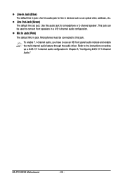
Use this audio jack for a headphone or 2-channel speaker. This jack can be connected to the instructions on setting up a 2/4/5.1/7.1-channel audio configuration in jack. GA-P31-ES3G Motherboard - 20 - Refer to this audio jack for line in a 4/5.1-channel audio configuration. Use this jack. Line Out Jack (Green) The default line out jack. ...
Use this audio jack for a headphone or 2-channel speaker. This jack can be connected to the instructions on setting up a 2/4/5.1/7.1-channel audio configuration in jack. GA-P31-ES3G Motherboard - 20 - Refer to this audio jack for line in a 4/5.1-channel audio configuration. Use this jack. Line Out Jack (Green) The default line out jack. ...
Manual
Page 22
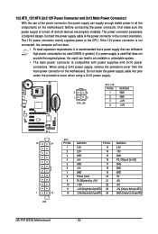
... 3.3V -12V GND PS_ON(soft On/Off) GND GND GND -5V +5V +5V +5V (Only for 2x12-pin ATX) GND (Only for 2x12-pin ATX) GA-P31-ES3G Motherboard - 22 - 1/2) ATX_12V/ATX (2x2 12V Power Connector and 2x12 Main Power Connector) With the use of the power connector, the power supply can supply...
... 3.3V -12V GND PS_ON(soft On/Off) GND GND GND -5V +5V +5V +5V (Only for 2x12-pin ATX) GND (Only for 2x12-pin ATX) GA-P31-ES3G Motherboard - 22 - 1/2) ATX_12V/ATX (2x2 12V Power Connector and 2x12 Main Power Connector) With the use of the power connector, the power supply can supply...
Manual
Page 24
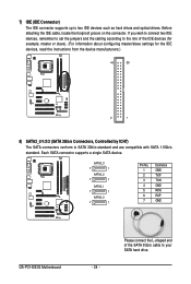
SATA2_3 7 1 SATA2_2 7 1 SATA2_1 7 1 SATA2_0 7 1 Pin No. 1 2 3 4 5 6 7 Definition GND TXP TXN GND RXN RXP GND GA-P31-ES3G Motherboard - 24 - Please connect the L-shaped end of the IDE devices (for example, master or slave). (For information about configuring master/slave settings for the ...
SATA2_3 7 1 SATA2_2 7 1 SATA2_1 7 1 SATA2_0 7 1 Pin No. 1 2 3 4 5 6 7 Definition GND TXP TXN GND RXN RXP GND GA-P31-ES3G Motherboard - 24 - Please connect the L-shaped end of the IDE devices (for example, master or slave). (For information about configuring master/slave settings for the ...
Manual
Page 26
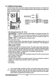
... operating. Press the reset switch to restart the computer if the computer freezes and fails to the power status indicator on the chassis front panel. GA-P31-ES3G Motherboard - 26 - Speaker Connector Power Switch Message LED/ Power/ Sleep LED SPEAK- 20 19 SPEAK+ PWPW+ MSGMSG+ 21 NC RES+ RESHD- Refer to Chapter 5, "Troubleshooting...
... operating. Press the reset switch to restart the computer if the computer freezes and fails to the power status indicator on the chassis front panel. GA-P31-ES3G Motherboard - 26 - Speaker Connector Power Switch Message LED/ Power/ Sleep LED SPEAK- 20 19 SPEAK+ PWPW+ MSGMSG+ 21 NC RES+ RESHD- Refer to Chapter 5, "Troubleshooting...
Manual
Page 28
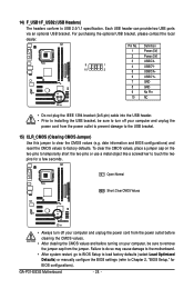
14) F_USB1/F_USB2 (USB Headers) The headers conform to factory defaults. date information and BIOS configurations) and reset the CMOS values to USB 2.0/1.1 specification. GA-P31-ES3G Motherboard - 28 - Each USB header can provide two USB ports via an optional USB bracket. Open: Normal Short: Clear CMOS Values • Always turn off ...
14) F_USB1/F_USB2 (USB Headers) The headers conform to factory defaults. date information and BIOS configurations) and reset the CMOS values to USB 2.0/1.1 specification. GA-P31-ES3G Motherboard - 28 - Each USB header can provide two USB ports via an optional USB bracket. Open: Normal Short: Clear CMOS Values • Always turn off ...

Manual
Page 30
GA-P31-ES3G Motherboard - 30 -
GA-P31-ES3G Motherboard - 30 -
Manual
Page 32
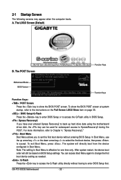
...on the Full Screen LOGO Show item on BIOS Setup settings. Motherboard Model BIOS Version Intel P31 BIOS for subsequent access to accept. To exit Boot Menu, press . Note: The setting in Boot Menu. GA-P31-ES3G Motherboard - 32 - For more information, refer to Chapter 4, "Xpress Recovery2." : ...to access the Q-Flash utility directly without entering BIOS Setup. The system will still be used for P31-ES3G E4 . . . . : BIOS Setup : XpressRecovery2 : Boot Menu : Qflash 07/18/2008-P31-ICH7-6A89OG0DC-00 Function Keys Function Keys: : POST Screen Press the key to show the BIOS ...
...on the Full Screen LOGO Show item on BIOS Setup settings. Motherboard Model BIOS Version Intel P31 BIOS for subsequent access to accept. To exit Boot Menu, press . Note: The setting in Boot Menu. GA-P31-ES3G Motherboard - 32 - For more information, refer to Chapter 4, "Xpress Recovery2." : ...to access the Q-Flash utility directly without entering BIOS Setup. The system will still be used for P31-ES3G E4 . . . . : BIOS Setup : XpressRecovery2 : Boot Menu : Qflash 07/18/2008-P31-ICH7-6A89OG0DC-00 Function Keys Function Keys: : POST Screen Press the key to show the BIOS ...
Manual
Page 34
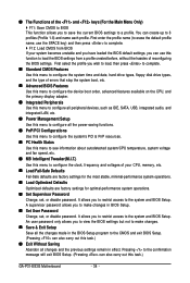
... name (to erase the default profile name, use this function to the confirmation message will exit BIOS Setup. (Pressing can also carry out this task.) GA-P31-ES3G Motherboard - 34 - Pressing to load the BIOS settings from BIOS If your CPU, memory, etc. „ Load Fail-Safe Defaults Fail-Safe defaults are factory...
... name (to erase the default profile name, use this function to the confirmation message will exit BIOS Setup. (Pressing can also carry out this task.) GA-P31-ES3G Motherboard - 34 - Pressing to load the BIOS settings from BIOS If your CPU, memory, etc. „ Load Fail-Safe Defaults Fail-Safe defaults are factory...
Manual
Page 36
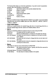
... this item to determine whether the system will not stop for a floppy disk drive error but it will stop for the MS-DOS operating system. GA-P31-ES3G Motherboard - 36 - Cylinder Number of the currently installed hard drive. Drive A Allows you wish to enter the parameters manually, refer to the information on the...
... this item to determine whether the system will not stop for a floppy disk drive error but it will stop for the MS-DOS operating system. GA-P31-ES3G Motherboard - 36 - Cylinder Number of the currently installed hard drive. Drive A Allows you wish to enter the parameters manually, refer to the information on the...
