Manual
Page 5
... Repair ...72 Chapter 5 Appendix ...73 5-1 Configuring SATA Hard Drive(s 73 5-1-1 Configuring AMD SB750 SATA Controllers 73 5-1-2 Configuring GIGABYTE SATA2 SATA Controller 79 5-1-3 Making a SATA RAID/AHCI Driver Diskette for Windows XP 85 5-1-4 Installing the SATA RAID/AHCI Driver and Operating System 86 5-2 ConfiguringAudio Input and Output 95 5-2-1 Configuring 2/4/5.1/7.1-Channel Audio 95 5-2-2 Configuring S/PDIF...
... Repair ...72 Chapter 5 Appendix ...73 5-1 Configuring SATA Hard Drive(s 73 5-1-1 Configuring AMD SB750 SATA Controllers 73 5-1-2 Configuring GIGABYTE SATA2 SATA Controller 79 5-1-3 Making a SATA RAID/AHCI Driver Diskette for Windows XP 85 5-1-4 Installing the SATA RAID/AHCI Driver and Operating System 86 5-2 ConfiguringAudio Input and Output 95 5-2-1 Configuring 2/4/5.1/7.1-Channel Audio 95 5-2-2 Configuring S/PDIF...
Manual
Page 10
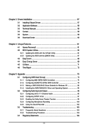
...back panel, 4 via the USB brackets connected to 1 floppy disk drive T.I. Support for SATA RAID 0, RAID 1, and JBOD iTE IT8720 chip: - 1 x floppy disk drive connector supporting up to the internal USB headers) GA-MA790XT-UD4P Motherboard - 10 - 1-2 Product Specifications CPU Hyper Transport Bus Chipset &#...system memory (Note 1) Dual channel memory architecture Support for DDR3 1666(O.C.)/1333/1066 MHz memory modules (Go to GIGABYTE's website for the latest memory support list.) Realtek ALC889A codec High Definition Audio 2/4/5.1/7.1-channel Support for Dolby®...
...back panel, 4 via the USB brackets connected to 1 floppy disk drive T.I. Support for SATA RAID 0, RAID 1, and JBOD iTE IT8720 chip: - 1 x floppy disk drive connector supporting up to the internal USB headers) GA-MA790XT-UD4P Motherboard - 10 - 1-2 Product Specifications CPU Hyper Transport Bus Chipset &#...system memory (Note 1) Dual channel memory architecture Support for DDR3 1666(O.C.)/1333/1066 MHz memory modules (Go to GIGABYTE's website for the latest memory support list.) Realtek ALC889A codec High Definition Audio 2/4/5.1/7.1-channel Support for Dolby®...

Manual
Page 26
GA-MA790XT-UD4P Motherboard - 26 - The AMD SB750 controller supports RAID 0, RAID 1, RAID 5, RAID 10, and JBOD. Pin No. Before attaching the IDE cable, locate the foolproof groove on configuring a RAID array. Definition 11 1 GND 2 TXP SATA2_5 SATA2_4 3 TXN 4 GND 5 RXN 6 RXP 7 GND SATA2_3 SATA2_2 ... supports a single SATA device. 7) IDE (IDE Connector) The IDE connector supports up to be an even number.) • A RAID 10 configuration requires at least two hard drives. If more than two hard drives are compatible with SATA 1.5Gb/s standard. Refer to ...
GA-MA790XT-UD4P Motherboard - 26 - The AMD SB750 controller supports RAID 0, RAID 1, RAID 5, RAID 10, and JBOD. Pin No. Before attaching the IDE cable, locate the foolproof groove on configuring a RAID array. Definition 11 1 GND 2 TXP SATA2_5 SATA2_4 3 TXN 4 GND 5 RXN 6 RXP 7 GND SATA2_3 SATA2_2 ... supports a single SATA device. 7) IDE (IDE Connector) The IDE connector supports up to be an even number.) • A RAID 10 configuration requires at least two hard drives. If more than two hard drives are compatible with SATA 1.5Gb/s standard. Refer to ...

Manual
Page 27
9) GSATA2_0/1 (SATA 3Gb/s Connectors, Controlled by GIGABYTE SATA2) The SATA connectors conform to Chapter 5, "Configuring SATA Hard Drive(s)," for instructions on configuring a RAID array. The LED is on the chassis to indicate system power status. The LED keeps blinking when the system is operating. ... requires at least two hard drives. The LED is off when the system is in S1 sleep state. The GIGABYTE SATA2 controller supports RAID 0, RAID 1, and JBOD. Hardware Installation Refer to SATA 3Gb/s standard and are compatible with SATA 1.5Gb/s standard. Please ...
9) GSATA2_0/1 (SATA 3Gb/s Connectors, Controlled by GIGABYTE SATA2) The SATA connectors conform to Chapter 5, "Configuring SATA Hard Drive(s)," for instructions on configuring a RAID array. The LED is on the chassis to indicate system power status. The LED keeps blinking when the system is operating. ... requires at least two hard drives. The LED is off when the system is in S1 sleep state. The GIGABYTE SATA2 controller supports RAID 0, RAID 1, and JBOD. Hardware Installation Refer to SATA 3Gb/s standard and are compatible with SATA 1.5Gb/s standard. Please ...
Manual
Page 47
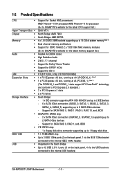
IDE Disables RAID for the SATA controller. OnChip SATA Port4/5 Mode (AMD SB750 South Bridge, SATA2_4/SATA2_5 connectors) This option is configurable only when OnChip SATA Type is ... of the integrated SATA controller. Native IDE Allows the SATA controller to operate in audio card instead of using the onboard audio, set to RAID or AHCI. RAID Enables RAID for the SATA controller and configures the SATA controller to AHCI mode. Advanced Host Controller Interface (AHCI) is set this item to enable...
IDE Disables RAID for the SATA controller. OnChip SATA Port4/5 Mode (AMD SB750 South Bridge, SATA2_4/SATA2_5 connectors) This option is configurable only when OnChip SATA Type is ... of the integrated SATA controller. Native IDE Allows the SATA controller to operate in audio card instead of using the onboard audio, set to RAID or AHCI. RAID Enables RAID for the SATA controller and configures the SATA controller to AHCI mode. Advanced Host Controller Interface (AHCI) is set this item to enable...
Manual
Page 48
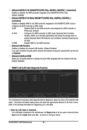
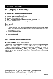
...LAN Cable Diagnostic Function) CMOS Setup Utility-Copyright (C) 1984-2009 Award Software SMART LAN Start detecting at Port..... GA-MA790XT-UD4P Motherboard - 48 - RAID Enables RAID for diagnosing your LAN cable: When No LAN Cable Is Attached... Refer to the following information for the SATA... connectors) Enables or disables the SATA controller integrated in the GIGABYTE SATA 2 chip. (Default: Enabled) Onboard GSATA-II Ctrl Mode (GIGABYTE SATA2 Chip, GSATA2_0/GSATA2_1 connectors) Enables or disables RAID for the SATA controller and configures the SATA controller to PATA...
...LAN Cable Diagnostic Function) CMOS Setup Utility-Copyright (C) 1984-2009 Award Software SMART LAN Start detecting at Port..... GA-MA790XT-UD4P Motherboard - 48 - RAID Enables RAID for diagnosing your LAN cable: When No LAN Cable Is Attached... Refer to the following information for the SATA... connectors) Enables or disables the SATA controller integrated in the GIGABYTE SATA 2 chip. (Default: Enabled) Onboard GSATA-II Ctrl Mode (GIGABYTE SATA2 Chip, GSATA2_0/GSATA2_1 connectors) Enables or disables RAID for the SATA controller and configures the SATA controller to PATA...
Manual
Page 61
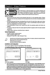
... card • Windows® XP with Xpress Recovery cannot be restored using Xpress Recovery2. • USB hard drives are not supported. • Hard drives in RAID/AHCI mode are different utilities. Supporting NTFS, FAT32, and FAT16 file systems, Xpress Recovery2 can only back up/restore the first physical hard drive that...
... card • Windows® XP with Xpress Recovery cannot be restored using Xpress Recovery2. • USB hard drives are not supported. • Hard drives in RAID/AHCI mode are different utilities. Supporting NTFS, FAT32, and FAT16 file systems, Xpress Recovery2 can only back up/restore the first physical hard drive that...
Manual
Page 64
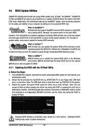
...GIGABYTE's website, download the latest compressed BIOS update file that support DualBIOS have two BIOS onboard, a main BIOS and a backup BIOS. During the POST, press the key to your computer by either pressing the key during the POST to an independent IDE/SATA controller, use FAT32/16/12 file system. 3. GA-MA790XT-UD4P...protection for the safety and stability of your floppy disk, USB flash drive, or hard drive. What is saved to a hard drive in RAID/AHCI mode or a hard drive attached to access Q-Flash. Embedded in the Windows environment. @BIOS will take over on the main BIOS....
...GIGABYTE's website, download the latest compressed BIOS update file that support DualBIOS have two BIOS onboard, a main BIOS and a backup BIOS. During the POST, press the key to your computer by either pressing the key during the POST to an independent IDE/SATA controller, use FAT32/16/12 file system. 3. GA-MA790XT-UD4P...protection for the safety and stability of your floppy disk, USB flash drive, or hard drive. What is saved to a hard drive in RAID/AHCI mode or a hard drive attached to access Q-Flash. Embedded in the Windows environment. @BIOS will take over on the main BIOS....

Manual
Page 65
... file from the floppy disk is updating the BIOS. appears, press to update BIOS?" Step 3: When the update process is saved to a hard drive in RAID/AHCI mode or a hard drive attached to an independent IDE/SATA controller, use the up or down arrow key to a floppy disk. Unique Features Updating...
... file from the floppy disk is updating the BIOS. appears, press to update BIOS?" Step 3: When the update process is saved to a hard drive in RAID/AHCI mode or a hard drive attached to an independent IDE/SATA controller, use the up or down arrow key to a floppy disk. Unique Features Updating...
Manual
Page 73
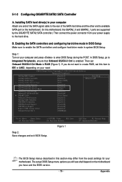
... you do not want to available SATA port on the motherboard. If you do not want to AHCI or RAID mode. - 73 - Configure SATA controller mode in RAID BIOS. (Note 1) D. C . B. Install the SATA RAID/AHCI driver and operating system. (Note 2) Before you begin Please prepare: • At least two SATA ... you may prepare only one end of the SATA signal cable to the rear of the SATA hard drive and the other end to create RAID array on your computer Attach one hard drive. • An empty formatted floppy disk. • Windows Vista/XP setup disk. • Motherboard driver disk...
... you do not want to available SATA port on the motherboard. If you do not want to AHCI or RAID mode. - 73 - Configure SATA controller mode in RAID BIOS. (Note 1) D. C . B. Install the SATA RAID/AHCI driver and operating system. (Note 2) Before you begin Please prepare: • At least two SATA ... you may prepare only one end of the SATA signal cable to the rear of the SATA hard drive and the other end to create RAID array on your computer Attach one hard drive. • An empty formatted floppy disk. • Windows Vista/XP setup disk. • Motherboard driver disk...

Manual
Page 74
... F1: General Help F7: Optimized Defaults Step 2: Save changes and exit BIOS Setup. To enable RAID for your computer and press to RAID. The BIOS Setup menus described in BIOS Setup Make sure to As SATA Type (Figure 1). GA-MA790XT-UD4P Motherboard - 74 - Ensure OnChip SATA Controller is enabled under Integrated Peripherals. B. Configuring SATA controller...
... F1: General Help F7: Optimized Defaults Step 2: Save changes and exit BIOS Setup. To enable RAID for your computer and press to RAID. The BIOS Setup menus described in BIOS Setup Make sure to As SATA Type (Figure 1). GA-MA790XT-UD4P Motherboard - 74 - Ensure OnChip SATA Controller is enabled under Integrated Peripherals. B. Configuring SATA controller...

Manual
Page 75
... press to enter the Controller Configuration window. To view controller settings, press to enter the View Drive Assignments window. RAID Option ROM Version 3.0.1540.47 (c) 2008 Advanced Micro Devices, Inc. Step 1: After the POST memory test begins and... Inc. [ Main Menu ] View Drive Assignments 1 ] Define LD 2 ] Delete LD 3 ] Controller Configuration 4 ] Press 1..4 to configure a RAID array. Configuring RAID set in RAID BIOS Enter the RAID BIOS setup utility to Select Option [ Keys Available ] Figure 3 [ESC] Exit - 75 - Figure 2 Step 2: Main Menu This is defined.....
... press to enter the Controller Configuration window. To view controller settings, press to enter the View Drive Assignments window. RAID Option ROM Version 3.0.1540.47 (c) 2008 Advanced Micro Devices, Inc. Step 1: After the POST memory test begins and... Inc. [ Main Menu ] View Drive Assignments 1 ] Define LD 2 ] Delete LD 3 ] Controller Configuration 4 ] Press 1..4 to configure a RAID array. Configuring RAID set in RAID BIOS Enter the RAID BIOS setup utility to Select Option [ Keys Available ] Figure 3 [ESC] Exit - 75 - Figure 2 Step 2: Main Menu This is defined.....
Manual
Page 76
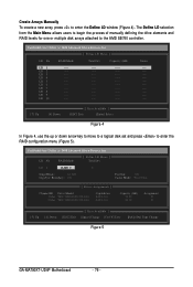
...to a logical disk set and press to enter the Define LD window (Figure 4). LD No RAID Mode [ Define LD Menu ] Total Drv LD 1 RAID 0 0 Stripe Block: 64 KB Gigabyte Boundary: ON Fast Init: ON Cache Mode: WriteThru [ Drives Assignments ] Channel:ID Drive ...ESC] Exit [ Keys Available ] [Space] Change [Ctrl-Y] Save [PgUp/Dn] Page Change Figure 5 GA-MA790XT-UD4P Motherboard - 76 - LD 4 ---- Create Arrays Manually To create a new array, press to enter the RAID configuration menu (Figure 5). LD 5 ---- The Define LD selection from the Main Menu allows users to begin ...
...to a logical disk set and press to enter the Define LD window (Figure 4). LD No RAID Mode [ Define LD Menu ] Total Drv LD 1 RAID 0 0 Stripe Block: 64 KB Gigabyte Boundary: ON Fast Init: ON Cache Mode: WriteThru [ Drives Assignments ] Channel:ID Drive ...ESC] Exit [ Keys Available ] [Space] Change [Ctrl-Y] Save [PgUp/Dn] Page Change Figure 5 GA-MA790XT-UD4P Motherboard - 76 - LD 4 ---- Create Arrays Manually To create a new array, press to enter the RAID configuration menu (Figure 5). LD 5 ---- The Define LD selection from the Main Menu allows users to begin ...

Manual
Page 77
...Press Ctrl-Y to Modify Array Capacity or press any other keys to set the array to the disk array. Figure 7 7. Under the RAID Mode section, press the key to use maximum capacity... This action adds the drive to its maximum capacity. 8. Press to return to Main... Drive Assignments The View Drive Assignments option in the Main Menu displays whether drives attached to the AMD SB750 controller are assigned to exit the RAID BIOS utility. Press + to set the capacity of disks assigned. 5. Under the Assignment column, drives are unassigned. After the creation is ...
...Press Ctrl-Y to Modify Array Capacity or press any other keys to set the array to the disk array. Figure 7 7. Under the RAID Mode section, press the key to use maximum capacity... This action adds the drive to its maximum capacity. 8. Press to return to Main... Drive Assignments The View Drive Assignments option in the Main Menu displays whether drives attached to the AMD SB750 controller are assigned to exit the RAID BIOS utility. Press + to set the capacity of disks assigned. 5. Under the Assignment column, drives are unassigned. After the creation is ...

Manual
Page 78
... 9) showing which drives are sure to delete the array or other key to abort. 3. Press to return to Delete LD Menu. Figure 9 GA-MA790XT-UD4P Motherboard - 78 - Delete an Array The Delete Array menu option allows for deletion of data. or press any other keys to abort... Press... + if you wish to enter the Delete LD Menu. LD No [ View LD Definition Menu ] RAID Mode Total Drv Capacity (GB) Status LD 1 RAID 0 2 157.99 Functional Stripe Block: 64KB Cache Mode: WriteThru [ Drives Assignments ] Channel:ID Drive Model 1:Mas WDC WD800JD...
... 9) showing which drives are sure to delete the array or other key to abort. 3. Press to return to Delete LD Menu. Figure 9 GA-MA790XT-UD4P Motherboard - 78 - Delete an Array The Delete Array menu option allows for deletion of data. or press any other keys to abort... Press... + if you wish to enter the Delete LD Menu. LD No [ View LD Definition Menu ] RAID Mode Total Drv Capacity (GB) Status LD 1 RAID 0 2 157.99 Functional Stripe Block: 64KB Cache Mode: WriteThru [ Drives Assignments ] Channel:ID Drive Model 1:Mas WDC WD800JD...
Manual
Page 79
..., ensure that Onboard GSATA-II Ctrl is enabled. On this motherboard, the GSATA2_0 and GSATA2_1 ports are supported by the GIGABYTE SATA2 SATA controller.) Then connect the power connector from the exact settings for your computer Attach one end of the SATA ... USB EHCI Controller USB Keyboard Support USB Mouse Support Legacy USB storage detect Onboard Serial Port 1 [Enabled] [Enabled] [Native IDE] [IDE] [Enabled] [Enabled] [RAID] [Enabled] [Disabled] [Press Enter] [Enabled] [Enabled] [Enabled] [Disabled] [Disabled] [Enabled] [3F8/IRQ4] Item Help Menu Level Move Enter:...
..., ensure that Onboard GSATA-II Ctrl is enabled. On this motherboard, the GSATA2_0 and GSATA2_1 ports are supported by the GIGABYTE SATA2 SATA controller.) Then connect the power connector from the exact settings for your computer Attach one end of the SATA ... USB EHCI Controller USB Keyboard Support USB Mouse Support Legacy USB storage detect Onboard Serial Port 1 [Enabled] [Enabled] [Native IDE] [IDE] [Enabled] [Enabled] [RAID] [Enabled] [Disabled] [Press Enter] [Enabled] [Enabled] [Enabled] [Disabled] [Disabled] [Enabled] [3F8/IRQ4] Item Help Menu Level Move Enter:...
Manual
Page 80
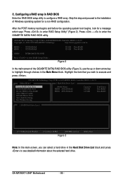
... system boot begins, look for a non-RAID configuration. Press + to enter RAID Setup Utility ... GA-MA790XT-UD4P Motherboard - 80 - http://www.gigabyte.com.tw HDD0 : HDD1 : ST3120026AS ST3120026AS 120 GB Non-RAID 120 GB Non-RAID ODD0 : DVDROM GO-D1600B Press to enter the GIGABYTE SATA2 RAID BIOS utility. PCIE-to-SATAII/IDE RAID Controller BIOS v1.06.59 [ Main Menu...
... system boot begins, look for a non-RAID configuration. Press + to enter RAID Setup Utility ... GA-MA790XT-UD4P Motherboard - 80 - http://www.gigabyte.com.tw HDD0 : HDD1 : ST3120026AS ST3120026AS 120 GB Non-RAID 120 GB Non-RAID ODD0 : DVDROM GO-D1600B Press to enter the GIGABYTE SATA2 RAID BIOS utility. PCIE-to-SATAII/IDE RAID Controller BIOS v1.06.59 [ Main Menu...

Manual
Page 81
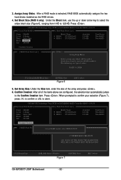
... [ESC]-Abort The Create New RAID block displays all the items that need to select RAID 0 (Stripe), RAID 1 (Mirror), or JBOD (Figure 5). Create a RAID Array: In the main screen, press on the Create RAID Disk Drive item. Steps: 1. GIGABYTE Technology Corp. Data striped for ...HDD0: ST3120026AS HDD1: ST3120026AS Available 120 GB 120 GB Type/Status Non-RAID Non-RAID Confirm Creation [ RAID Disk Drive List ] [ Help ] Select RAID Level RAID 0 RAID 1 JBOD - GIGABYTE Technology Corp. Then the Create New RAID screen appears (Figure 4). Enter Array Name: Under the Name item, ...
... [ESC]-Abort The Create New RAID block displays all the items that need to select RAID 0 (Stripe), RAID 1 (Mirror), or JBOD (Figure 5). Create a RAID Array: In the main screen, press on the Create RAID Disk Drive item. Steps: 1. GIGABYTE Technology Corp. Data striped for ...HDD0: ST3120026AS HDD1: ST3120026AS Available 120 GB 120 GB Type/Status Non-RAID Non-RAID Confirm Creation [ RAID Disk Drive List ] [ Help ] Select RAID Level RAID 0 RAID 1 JBOD - GIGABYTE Technology Corp. Then the Create New RAID screen appears (Figure 4). Enter Array Name: Under the Name item, ...
Manual
Page 82
...[DEL,BS]-Delete Number Figure 7 [ENTER]-Next [ESC]-Abort GA-MA790XT-UD4P Motherboard - 82 - Set Array Size: Under the Size item, enter the size of the items above are typical values: RAID 0-128KB []-Switch RAID Block Size [ENTER]-Next Figure 6 [ESC]-Abort 5. Confirm Creation... 6. PCIE-to abort. The following are configured, the selection bar automatically jumps to 128 KB. GIGABYTE Technology Corp. PCIE-to-SATAII/IDE RAID Controller BIOS v1.06.59 [ Create New RAID ] [ Hard Disk Drive List ] Name: GRAID Level: 0-Stripe Disks: Select Disk Block: ...
...[DEL,BS]-Delete Number Figure 7 [ENTER]-Next [ESC]-Abort GA-MA790XT-UD4P Motherboard - 82 - Set Array Size: Under the Size item, enter the size of the items above are typical values: RAID 0-128KB []-Switch RAID Block Size [ENTER]-Next Figure 6 [ESC]-Abort 5. Confirm Creation... 6. PCIE-to abort. The following are configured, the selection bar automatically jumps to 128 KB. GIGABYTE Technology Corp. PCIE-to-SATAII/IDE RAID Controller BIOS v1.06.59 [ Create New RAID ] [ Hard Disk Drive List ] Name: GRAID Level: 0-Stripe Disks: Select Disk Block: ...

Manual
Page 83
GIGABYTE Technology Corp. GIGABYTE Technology Corp. A small window displaying the array information will be displayed in the RAID Disk Drive List block (Figure 8). PCIE-to-SATAII/IDE RAID Controller BIOS v1.06.59 [ Main Menu ] [ Hard Disk Drive List ] Create RAID Disk Drive Delete RAID Disk Drive Revert HDD to Non-RAID...Without Saving Model Name HDD0: ST3120026AS HDD1: ST3120026AS Capacity Type/Status 120 GB RAID Inside 120 GB RAID Inside [ RAID Disk Drive List ] Model Name RDD0: GRAID RAID Level 0-Stripe Capacity Status 240 GB Normal Members(HDDx) 01 [...
GIGABYTE Technology Corp. GIGABYTE Technology Corp. A small window displaying the array information will be displayed in the RAID Disk Drive List block (Figure 8). PCIE-to-SATAII/IDE RAID Controller BIOS v1.06.59 [ Main Menu ] [ Hard Disk Drive List ] Create RAID Disk Drive Delete RAID Disk Drive Revert HDD to Non-RAID...Without Saving Model Name HDD0: ST3120026AS HDD1: ST3120026AS Capacity Type/Status 120 GB RAID Inside 120 GB RAID Inside [ RAID Disk Drive List ] Model Name RDD0: GRAID RAID Level 0-Stripe Capacity Status 240 GB Normal Members(HDDx) 01 [...


