
Manual
Page 4
Table of Contents Box Contents...6 Optional Items...6 GA-MA78LM-S2H/GA-MA78LM-S2 Motherboard Layout 7 Block Diagram...8 Chapter 1 Hardware Installation 9 1-1 Installation Precautions 9 1-2 Product Specifications 10 1-3 Installing the CPU and CPU Cooler 13 1-3-1 Installing the CPU 13 1-3-2 Installing the CPU Cooler 15 1-4 Installing the Memory 16 1-4-1 Dual Channel Memory Configuration 16 1-4-2 Installing a Memory 17 1-5 Installing an Expansion Card 18 1-6 Back...
Table of Contents Box Contents...6 Optional Items...6 GA-MA78LM-S2H/GA-MA78LM-S2 Motherboard Layout 7 Block Diagram...8 Chapter 1 Hardware Installation 9 1-1 Installation Precautions 9 1-2 Product Specifications 10 1-3 Installing the CPU and CPU Cooler 13 1-3-1 Installing the CPU 13 1-3-2 Installing the CPU Cooler 15 1-4 Installing the Memory 16 1-4-1 Dual Channel Memory Configuration 16 1-4-2 Installing a Memory 17 1-5 Installing an Expansion Card 18 1-6 Back...
Manual
Page 8
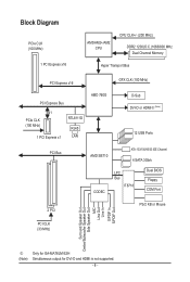
Block Diagram PCIe CLK (100 MHz) 1 PCI Express x16 AM3/AM2+/AM2 CPU CPU CLK+/- (200 MHz) DDR2 1200(O.C.)1066/800 MHz Dual Channel Memory Hyper Transport Bus PCI Express x16 GFX CLK (100 MHz) PCI Express Bus x1 PCIe CLK (100 MHz) 1 PCI Express x1 RTL8111D RJ45 LAN AMD ... CLK (33 MHz) Surround Speaker Out Center/Subwoofer Speaker Out Side Speaker Out MIC Line Out Line In S/PDIF In S/PDIF Out j (Note) Only for GA-MA78LM-S2H Simultaneous output for DVI-D and HDMI is not supported. - 8 -
Block Diagram PCIe CLK (100 MHz) 1 PCI Express x16 AM3/AM2+/AM2 CPU CPU CLK+/- (200 MHz) DDR2 1200(O.C.)1066/800 MHz Dual Channel Memory Hyper Transport Bus PCI Express x16 GFX CLK (100 MHz) PCI Express Bus x1 PCIe CLK (100 MHz) 1 PCI Express x1 RTL8111D RJ45 LAN AMD ... CLK (33 MHz) Surround Speaker Out Center/Subwoofer Speaker Out Side Speaker Out MIC Line Out Line In S/PDIF In S/PDIF Out j (Note) Only for GA-MA78LM-S2H Simultaneous output for DVI-D and HDMI is not supported. - 8 -

Manual
Page 9
... 1-1 Installation Precautions The motherboard contains numerous delicate electronic circuits and components which can lead to damage to system components as well as a motherboard, CPU or memory. These stickers are required for warranty validation. • Always remove the AC power by your hardware components are connected. • To prevent damage to the...
... 1-1 Installation Precautions The motherboard contains numerous delicate electronic circuits and components which can lead to damage to system components as well as a motherboard, CPU or memory. These stickers are required for warranty validation. • Always remove the AC power by your hardware components are connected. • To prevent damage to the...
Manual
Page 10
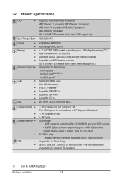
...to 8 GB of system memory (Note 1) Dual channel memory architecture Support for DDR2 1200 (O.C.)/1066/800 MHz memory modules Support for non-ECC memory modules (Go to GIGABYTE's website for the latest memory support list.) Integrated in ...the North Bridge: - 1 x D-Sub port - 1 x DVI-D port (Note 2) (Note 3) - 1 x HDMI port j(Note 3) Realtek ALC888B codec High Definition Audio 2/4/5.1/7.1-channel (Note 4) Support for S/PDIF Out Support for S/PDIF In Support for GA-MA78LM...
...to 8 GB of system memory (Note 1) Dual channel memory architecture Support for DDR2 1200 (O.C.)/1066/800 MHz memory modules Support for non-ECC memory modules (Go to GIGABYTE's website for the latest memory support list.) Integrated in ...the North Bridge: - 1 x D-Sub port - 1 x DVI-D port (Note 2) (Note 3) - 1 x HDMI port j(Note 3) Realtek ALC888B codec High Definition Audio 2/4/5.1/7.1-channel (Note 4) Support for S/PDIF Out Support for S/PDIF In Support for GA-MA78LM...
Manual
Page 12
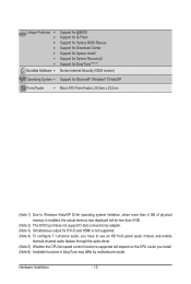
... Form Factor; 24.3cm x 22.0cm (Note 1) Due to Windows Vista/XP 32-bit operating system limitation, when more than 4 GB of physical memory is installed, the actual memory size displayed will be less than 4 GB. (Note 2) The DVI-D port does not support D-Sub connection by adapter. (Note 3) Simultaneous output for DVI...
... Form Factor; 24.3cm x 22.0cm (Note 1) Due to Windows Vista/XP 32-bit operating system limitation, when more than 4 GB of physical memory is installed, the actual memory size displayed will be less than 4 GB. (Note 2) The DVI-D port does not support D-Sub connection by adapter. (Note 3) Simultaneous output for DVI...

Manual
Page 13
...the CPU. 1-3 Installing the CPU and CPU Cooler Read the following guidelines before installing the CPU to your hardware specifications including the CPU, graphics card, memory, hard drive, etc. 1-3-1 Installing the CPU A. Locate the pin one of the CPU. • Do not turn off the computer and unplug the...power cord from the power outlet before you begin to install the CPU: • Make sure that the motherboard supports the CPU. (Go to GIGABYTE's website for the latest CPU support list.) • Always turn on the computer if the CPU cooler is not recommended that the system bus ...
...the CPU. 1-3 Installing the CPU and CPU Cooler Read the following guidelines before installing the CPU to your hardware specifications including the CPU, graphics card, memory, hard drive, etc. 1-3-1 Installing the CPU A. Locate the pin one of the CPU. • Do not turn off the computer and unplug the...power cord from the power outlet before you begin to install the CPU: • Make sure that the motherboard supports the CPU. (Go to GIGABYTE's website for the latest CPU support list.) • Always turn on the computer if the CPU cooler is not recommended that the system bus ...

Manual
Page 16
... enabled if only one direction. When enabling Dual Channel mode with two memory modules, it is recommended that the motherboard supports the memory. A memory module can be used . (Go to GIGABYTE's website for the latest memory support list.) • Always turn off the computer and unplug the... power cord from the power outlet before installing the memory in only one DDR2 memory module is installed, ...
... enabled if only one direction. When enabling Dual Channel mode with two memory modules, it is recommended that the motherboard supports the memory. A memory module can be used . (Go to GIGABYTE's website for the latest memory support list.) • Always turn off the computer and unplug the... power cord from the power outlet before installing the memory in only one DDR2 memory module is installed, ...

Manual
Page 17
... can only fit in one direction. Step 2: The clips at both ends of the memory module. Step 1: Note the orientation of the socket will snap into the memory socket. As indicated in the memory sockets. 1-4-2 Installing a Memory Before installing a memory module , make sure to turn off the computer and unplug the power cord from the... power outlet to prevent damage to install DDR2 DIMMs on this motherboard. Follow the steps below to correctly install your memory modules in the picture on the left, place your fingers on the top edge of the...
... can only fit in one direction. Step 2: The clips at both ends of the memory module. Step 1: Note the orientation of the socket will snap into the memory socket. As indicated in the memory sockets. 1-4-2 Installing a Memory Before installing a memory module , make sure to turn off the computer and unplug the power cord from the... power outlet to prevent damage to install DDR2 DIMMs on this motherboard. Follow the steps below to correctly install your memory modules in the picture on the left, place your fingers on the top edge of the...

Manual
Page 20
... configure 7.1-channel audio, you have to 1 Gbps data rate. The table below . • CPU: AMD Phenom™ X3 processor or above • Memory: Two 1 GB DDR2 800 MHz memory modules with dual channel mode enabled • BIOS Setup: At least 256 MB of the LAN port LEDs. Dual Display Configurations: This motherboard...
... configure 7.1-channel audio, you have to 1 Gbps data rate. The table below . • CPU: AMD Phenom™ X3 processor or above • Memory: Two 1 GB DDR2 800 MHz memory modules with dual channel mode enabled • BIOS Setup: At least 256 MB of the LAN port LEDs. Dual Display Configurations: This motherboard...

Manual
Page 34
... profile name (to erase the default profile name, use this task.) BIOS Setup - 34 - Pressing to load the BIOS settings from BIOS If your CPU, memory, etc. Standard CMOS Features Use this menu to configure the system time and date, hard drive types, floppy disk drive types, and the type...
... profile name (to erase the default profile name, use this task.) BIOS Setup - 34 - Pressing to load the BIOS settings from BIOS If your CPU, memory, etc. Standard CMOS Features Use this menu to configure the system time and date, hard drive types, floppy disk drive types, and the type...

Manual
Page 35
...prevent system instability or other unexpected results. (Inadequately altering the settings may result in system's failure to CPU, chipset, or memory and reduce the useful life of these components. BIOS Setup If this feature. - 35 - 2-3 MB Intelligent Tweaker(M.I.T.) CMOS...CPU Frequency(MHz) PCIE Clock(MHz) HT Link Width HT Link Frequency VGA Core Clock control x VGA Core Clock(MHz) Set Memory Clock x Memory Clock System Voltage Optimized ******** System Voltage Control x DDR2 Voltage Control x NorthBridge Volt Control x SouthBridge Volt Control x CPU NB ...
...prevent system instability or other unexpected results. (Inadequately altering the settings may result in system's failure to CPU, chipset, or memory and reduce the useful life of these components. BIOS Setup If this feature. - 35 - 2-3 MB Intelligent Tweaker(M.I.T.) CMOS...CPU Frequency(MHz) PCIE Clock(MHz) HT Link Width HT Link Frequency VGA Core Clock control x VGA Core Clock(MHz) Set Memory Clock x Memory Clock System Voltage Optimized ******** System Voltage Control x DDR2 Voltage Control x NorthBridge Volt Control x SouthBridge Volt Control x CPU NB ...

Manual
Page 37
...BIOS to X2.66. The adjustable range is highly recommended that supports this feature. - 37 - Auto lets BIOS automatically set the memory clock. X2.66 Sets Memory Clock to automatically adjust the CPU host frequency. The adjustable range is dependent on the CPU being used . Important It is from ...clock. This item is configurable only if the VGA Core Clock control option is from 200 MHz to 200 MHz~2.6 GHz. X3.33 Sets Memory Clock to X4.00. BIOS Setup Auto BIOS will automatically adjust the HT Link Frequency. (Default) 200 MHz~2.6 GHz Sets HT Link ...
...BIOS to X2.66. The adjustable range is highly recommended that supports this feature. - 37 - Auto lets BIOS automatically set the memory clock. X2.66 Sets Memory Clock to automatically adjust the CPU host frequency. The adjustable range is dependent on the CPU being used . Important It is from ...clock. This item is configurable only if the VGA Core Clock control option is from 200 MHz to 200 MHz~2.6 GHz. X3.33 Sets Memory Clock to X4.00. BIOS Setup Auto BIOS will automatically adjust the HT Link Frequency. (Default) 200 MHz~2.6 GHz Sets HT Link ...

Manual
Page 38
... may result in damage to your CPU. Auto lets the BIOS automatically set the system voltages as required. (Default) +0.100V ~ +0.300V Increases memory voltage by 0.100V to 0.300V at 0.1V increment. Normal Supplies the South Bridge voltage as required. Auto sets the CPU voltage as required. ...increment. Normal CPU Vcore Displays the normal operating voltage of your CPU or reduce the useful life of the CPU. DDR 533 Sets Memory Clock to manually set the system voltages. The adjustable range is dependent on the CPU being installed. (Default: Normal) Note: Increasing ...
... may result in damage to your CPU. Auto lets the BIOS automatically set the system voltages as required. (Default) +0.100V ~ +0.300V Increases memory voltage by 0.100V to 0.300V at 0.1V increment. Normal Supplies the South Bridge voltage as required. Auto sets the CPU voltage as required. ...increment. Normal CPU Vcore Displays the normal operating voltage of your CPU or reduce the useful life of the CPU. DDR 533 Sets Memory Clock to manually set the system voltages. The adjustable range is dependent on the CPU being installed. (Default: Normal) Note: Increasing ...

Manual
Page 39
... 3 Master } IDE Channel 3 Slave [None] [None] [None] [None] [None] [None] [None] [None] Drive A Floppy 3 Mode Support [1.44M, 3.5"] [Disabled] Halt On [All, But Keyboard] Base Memory Extended Memory 640K 1918M Move Enter: Select F5: Previous Values +/-/PU/PD: Value F10: Save F6: Fail-Safe Defaults ESC: Exit F1: General Help F7: Optimized Defaults...
... 3 Master } IDE Channel 3 Slave [None] [None] [None] [None] [None] [None] [None] [None] Drive A Floppy 3 Mode Support [1.44M, 3.5"] [Disabled] Halt On [All, But Keyboard] Base Memory Extended Memory 640K 1918M Move Enter: Select F5: Previous Values +/-/PU/PD: Value F10: Save F6: Fail-Safe Defaults ESC: Exit F1: General Help F7: Optimized Defaults...

Manual
Page 40
... None. BIOS Setup - 40 - Floppy 3 Mode Support Allows you to determine whether the system will not stop . Base Memory Also called conventional memory. Halt On Allows you to select the type of sectors. No Errors The system boot will stop for the MS-DOS operating... system. Landing Zone Landing zone. Extended Memory The amount of cylinders. Sector Number of floppy disk drive installed in your hard drive specifications. Options are: None, 360K/5.25", ...
... None. BIOS Setup - 40 - Floppy 3 Mode Support Allows you to determine whether the system will not stop . Base Memory Also called conventional memory. Halt On Allows you to select the type of sectors. No Errors The system boot will stop for the MS-DOS operating... system. Landing Zone Landing zone. Extended Memory The amount of cylinders. Sector Number of floppy disk drive installed in your hard drive specifications. Options are: None, 360K/5.25", ...

Manual
Page 41
... solely for the onboard graphics controller. When enabled, the CPU core frequency and voltage will use only this memory for GA-MA78LM-S2H (Note) This item appears only if you to determine whether to HDD Init Display First [UMA] [Auto] Disabled [D-SUB/DVI] [Disabled] ...First Boot Device Second Boot Device Third Boot Device Password Check HDD S.M.A.R.T. Capability Away Mode Backup BIOS Image to allocate system memory for the onboard graphics controller. AMD C1E Support (Note) Enables or disables the C1E CPU power-saving function in independent partitions. ...
... solely for the onboard graphics controller. When enabled, the CPU core frequency and voltage will use only this memory for GA-MA78LM-S2H (Note) This item appears only if you to determine whether to HDD Init Display First [UMA] [Auto] Disabled [D-SUB/DVI] [Disabled] ...First Boot Device Second Boot Device Third Boot Device Password Check HDD S.M.A.R.T. Capability Away Mode Backup BIOS Image to allocate system memory for the onboard graphics controller. AMD C1E Support (Note) Enables or disables the C1E CPU power-saving function in independent partitions. ...

Manual
Page 47
...) HPET Support (Note) Enables or disables High Precision Event Timer (HPET) for the password, press again without entering the password to clear the password settings. Memory The system returns to its last known awake state upon the return of Month): Turn on the system at least 1A on a specific day in...
...) HPET Support (Note) Enables or disables High Precision Event Timer (HPET) for the password, press again without entering the password to clear the password settings. Memory The system returns to its last known awake state upon the return of Month): Turn on the system at least 1A on a specific day in...
Manual
Page 59
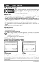
Installing Windows Vista and Partitioning the Hard Drive Step 1: Click Drive options. System Requirements: • At least 512 MB of system memory • VESA compatible graphics card • Windows XP with Xpress Recovery cannot be restored using Xpress Recovery2. • USB hard drives are not supported. • ...
Installing Windows Vista and Partitioning the Hard Drive Step 1: Click Drive options. System Requirements: • At least 512 MB of system memory • VESA compatible graphics card • Windows XP with Xpress Recovery cannot be restored using Xpress Recovery2. • USB hard drives are not supported. • ...

Manual
Page 66
...to load previous settings from the buzzer or use your ATI or NVIDIA graphics card. Available functions in Windows environment. The Memory tab provides information on the installed CPU and motherboard. Incorrectly doing overclock/overvoltage may result in the notification area. Unique Features ... you fully know each function of these changes to take effect or click Default to restore to default values. 4-3 EasyTune 6 GIGABYTE's EasyTune 6 is a simple and easy-to-use interface that allows users to fine-tune their system-related information without the ...
...to load previous settings from the buzzer or use your ATI or NVIDIA graphics card. Available functions in Windows environment. The Memory tab provides information on the installed CPU and motherboard. Incorrectly doing overclock/overvoltage may result in the notification area. Unique Features ... you fully know each function of these changes to take effect or click Default to restore to default values. 4-3 EasyTune 6 GIGABYTE's EasyTune 6 is a simple and easy-to-use interface that allows users to fine-tune their system-related information without the ...

Manual
Page 71
... for a message which says "Press to enter FastBuild (tm) Utility" (Figure 2). To create an array, press to enter FastBuild (tm) Utility... Step 1: After the POST memory test begins and before the operating system boot begins, look for a non-RAID configuration. Appendix Option ROM Utility (c) 2008 Advanced Micro Devices, Inc. [ Main Menu...
... for a message which says "Press to enter FastBuild (tm) Utility" (Figure 2). To create an array, press to enter FastBuild (tm) Utility... Step 1: After the POST memory test begins and before the operating system boot begins, look for a non-RAID configuration. Appendix Option ROM Utility (c) 2008 Advanced Micro Devices, Inc. [ Main Menu...


