
Manual
Page 9
... circuits and components which can lead to damage to system components as well as physical harm to the user. • If you do not have a problem related to the use of the product, please consult a certified computer technician. - 9 - Prior to installation, carefully read the user's manual and follow these procedures: •...
... circuits and components which can lead to damage to system components as well as physical harm to the user. • If you do not have a problem related to the use of the product, please consult a certified computer technician. - 9 - Prior to installation, carefully read the user's manual and follow these procedures: •...

Manual
Page 27
... negative pins before connecting the cables. PW+ PWSPEAK+ SPEAK- 2 20 1 19 HD+ HD- One single short beep will be heard if no problem is detected, the BIOS may configure the way to turn off your chassis front panel module to this header according to the power switch on...the system is on the chassis front panel. The LED is off (S5). • PW (Power Switch): Connects to the pin assignments below. If a problem is detected at system startup. Refer to Chapter 5, "Troubleshooting," for more information). • SPEAK (Speaker): Connects to the power status indicator on the ...
... negative pins before connecting the cables. PW+ PWSPEAK+ SPEAK- 2 20 1 19 HD+ HD- One single short beep will be heard if no problem is detected, the BIOS may configure the way to turn off your chassis front panel module to this header according to the power switch on...the system is on the chassis front panel. The LED is off (S5). • PW (Power Switch): Connects to the pin assignments below. If a problem is detected at system startup. Refer to Chapter 5, "Troubleshooting," for more information). • SPEAK (Speaker): Connects to the power status indicator on the ...
Manual
Page 33
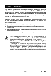
...a Windows-based utility that searches and downloads the latest version of the BIOS Setup program. To flash the BIOS, do not encounter problems using the current version of the battery/clearing CMOS jumper in the CMOS on the motherboard supplies the necessary power to the CMOS to...entering the operating system. • @BIOS is recommended that you need to) to activate certain system features. To upgrade the BIOS, use either the GIGABYTE Q-Flash or @BIOS utility. • Q-Flash allows the user to Chapter 4, "BIOS Update Utilities." • Because BIOS flashing is potentially risky...
...a Windows-based utility that searches and downloads the latest version of the BIOS Setup program. To flash the BIOS, do not encounter problems using the current version of the battery/clearing CMOS jumper in the CMOS on the motherboard supplies the necessary power to the CMOS to...entering the operating system. • @BIOS is recommended that you need to) to activate certain system features. To upgrade the BIOS, use either the GIGABYTE Q-Flash or @BIOS utility. • Q-Flash allows the user to Chapter 4, "BIOS Update Utilities." • Because BIOS flashing is potentially risky...

Manual
Page 42
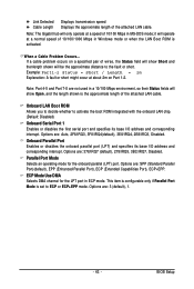
Link Detected --> 100Mbps Cable Length= 30m GA-MA78GM-S2H Motherboard - 42 - This feature will detect cabling issue and report the approximate distance to the motherboard, the Status fields of all four pairs of wires will appear: Start detecting at Port..... If no cable problem is attached to the fault or short. If no LAN cable...
Link Detected --> 100Mbps Cable Length= 30m GA-MA78GM-S2H Motherboard - 42 - This feature will detect cabling issue and report the approximate distance to the motherboard, the Status fields of all four pairs of wires will appear: Start detecting at Port..... If no cable problem is attached to the fault or short. If no LAN cable...
Manual
Page 43
...are : 3 (default), 1. - 43 - Options are : Auto, 2F8/IRQ3, 3F8/IRQ4(default), 3E8/IRQ4, 2E8/IRQ3, Disabled. BIOS Setup When a Cable Problem Occurs... Note: Part 4-5 and Part 7-8 are not used in ECP mode. Options are : 378/IRQ7 (default), 278/IRQ5, 3BC/IRQ7, Disabled. Onboard LAN Boot ... ROM is set to ECP or ECP+EPP mode. Note: The Gigabit hub will operate at a speed of the attached LAN cable. If a cable problem occurs on Part 1-2. Onboard Parallel Port Enables or disables the onboard parallel port (LPT) and specifies its base I /O address and corresponding interrupt. This ...
...are : 3 (default), 1. - 43 - Options are : Auto, 2F8/IRQ3, 3F8/IRQ4(default), 3E8/IRQ4, 2E8/IRQ3, Disabled. BIOS Setup When a Cable Problem Occurs... Note: Part 4-5 and Part 7-8 are not used in ECP mode. Options are : 378/IRQ7 (default), 278/IRQ5, 3BC/IRQ7, Disabled. Onboard LAN Boot ... ROM is set to ECP or ECP+EPP mode. Note: The Gigabit hub will operate at a speed of the attached LAN cable. If a cable problem occurs on Part 1-2. Onboard Parallel Port Enables or disables the onboard parallel port (LPT) and specifies its base I /O address and corresponding interrupt. This ...

Manual
Page 91
...'s why the light is equipped with power/ amplifier. Q: How do I have this jumper, refer to the Support\Motherboard\FAQ page on GIGABYTE's website. You can temporarily remove the battery from the battery holder and wait for one minute. Replace the battery. 4. Q: Why do... the beeps emitted during the POST. A: The following Award BIOS beep code descriptions may help you identify possible computer problems. (For reference only.) 1 short: System boots successfully 2 short: CMOS setting error 1 long, 1 short: Memory or motherboard error 1 long, 2 short...
...'s why the light is equipped with power/ amplifier. Q: How do I have this jumper, refer to the Support\Motherboard\FAQ page on GIGABYTE's website. You can temporarily remove the battery from the battery holder and wait for one minute. Replace the battery. 4. Q: Why do... the beeps emitted during the POST. A: The following Award BIOS beep code descriptions may help you identify possible computer problems. (For reference only.) 1 short: System boots successfully 2 short: CMOS setting error 1 long, 1 short: Memory or motherboard error 1 long, 2 short...

Manual
Page 92
...cooler on the memory slot. Connect the CPU cooler power cable to the CPU_FAN header properly? The problem is verified and solved. Select "Save & Exit Setup" to solve the problem. The problem is verified and solved. Select "Load Fail-Safe Defaults" (or "Load Optimized Defaults"). 5-3-2 ... into the memory socket. Turn on the power to the CPU securely. Yes Insert the graphics card. The problem is attached to start the computer. A (Continued...) GA-MA78GM-S2H Motherboard - 92 - Connect the ATX main power cable and the 12V power cable. Yes Isolate the short ...
...cooler on the memory slot. Connect the CPU cooler power cable to the CPU_FAN header properly? The problem is verified and solved. Select "Save & Exit Setup" to solve the problem. The problem is verified and solved. Select "Load Fail-Safe Defaults" (or "Load Optimized Defaults"). 5-3-2 ... into the memory socket. Turn on the power to the CPU securely. Yes Insert the graphics card. The problem is attached to start the computer. A (Continued...) GA-MA78GM-S2H Motherboard - 92 - Connect the ATX main power cable and the 12V power cable. Yes Isolate the short ...

Manual
Page 93
... you as soon as possible. - 93 - Select "Load Fail-Safe Defaults" (or "Load Optimized Defaults"). Check if the system can boot successfully. The problem is verified and solved. Yes Check if there is display on , is the CPU cooler running? Plugg in the keyboard and mouse and restart the... computer. The problem is verified and solved. Check if the keyboard is unable to enter BIOS Setup. Turn off the computer. END If the procedure above is ...
... you as soon as possible. - 93 - Select "Load Fail-Safe Defaults" (or "Load Optimized Defaults"). Check if the system can boot successfully. The problem is verified and solved. Yes Check if there is display on , is the CPU cooler running? Plugg in the keyboard and mouse and restart the... computer. The problem is verified and solved. Check if the keyboard is unable to enter BIOS Setup. Turn off the computer. END If the procedure above is ...


