Manual
Page 3
... motherboard BIOS, drivers, or when looking for technical information. For product-related information, check on our website at: http://www.gigabyte.com.tw Identifying Your Motherboard Revision The revision number on our website. Changes to assist in this manual are legally registered to ...use of the product, read the Quick Installation Guide included with the product. Documentation Classifications In order to the specifications and features in any means without prior notice. Check...
... motherboard BIOS, drivers, or when looking for technical information. For product-related information, check on our website at: http://www.gigabyte.com.tw Identifying Your Motherboard Revision The revision number on our website. Changes to assist in this manual are legally registered to ...use of the product, read the Quick Installation Guide included with the product. Documentation Classifications In order to the specifications and features in any means without prior notice. Check...
Manual
Page 4
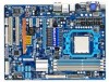
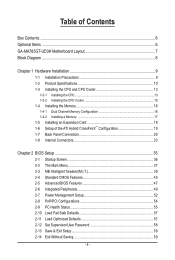
Table of Contents Box Contents...6 Optional Items...6 GA-MA785GT-UD3H Motherboard Layout 7 Block Diagram...8 Chapter 1 Hardware Installation 9 1-1 Installation Precautions 9 1-2 Product Specifications 10 1-3 Installing the CPU and CPU Cooler 13 1-3-1 Installing the CPU 13 1-3-2 Installing the CPU Cooler 15 1-4 Installing the Memory 16 1-4-1 Dual Channel Memory Configuration 16 1-4-2 Installing a Memory 17 1-5 Installing an Expansion Card 18 1-6 Setup of the ATI Hybrid CrossFireX™...
Table of Contents Box Contents...6 Optional Items...6 GA-MA785GT-UD3H Motherboard Layout 7 Block Diagram...8 Chapter 1 Hardware Installation 9 1-1 Installation Precautions 9 1-2 Product Specifications 10 1-3 Installing the CPU and CPU Cooler 13 1-3-1 Installing the CPU 13 1-3-2 Installing the CPU Cooler 15 1-4 Installing the Memory 16 1-4-1 Dual Channel Memory Configuration 16 1-4-2 Installing a Memory 17 1-5 Installing an Expansion Card 18 1-6 Setup of the ATI Hybrid CrossFireX™...
Manual
Page 5
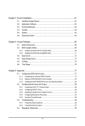
Chapter 3 Drivers Installation 61 3-1 Installing Chipset Drivers 61 3-2 Application Software 62 3-3 Technical Manuals 62 3-4 Contact...63 3-5 System...63 3-6 Download Center 64 Chapter 4 Unique Features 65 4-1 Xpress ...Repair...76 Chapter 5 Appendix...77 5-1 Configuring SATA Hard Drive(s 77 5-1-1 Configuring the Onboard SATA Controller 77 5-1-2 Making a SATA RAID/AHCI Driver Diskette 83 5-1-3 Installing the SATA RAID/AHCI Driver and Operating System 84 5-2 Configuring Audio Input and Output 88 5-2-1 Configuring 2/4/5.1/7.1-Channel Audio 88 5-2-2 Configuring S/PDIF In/Out 90 5-2-3...
Chapter 3 Drivers Installation 61 3-1 Installing Chipset Drivers 61 3-2 Application Software 62 3-3 Technical Manuals 62 3-4 Contact...63 3-5 System...63 3-6 Download Center 64 Chapter 4 Unique Features 65 4-1 Xpress ...Repair...76 Chapter 5 Appendix...77 5-1 Configuring SATA Hard Drive(s 77 5-1-1 Configuring the Onboard SATA Controller 77 5-1-2 Making a SATA RAID/AHCI Driver Diskette 83 5-1-3 Installing the SATA RAID/AHCI Driver and Operating System 84 5-2 Configuring Audio Input and Output 88 5-2-1 Configuring 2/4/5.1/7.1-Channel Audio 88 5-2-2 Configuring S/PDIF In/Out 90 5-2-3...
Manual
Page 6
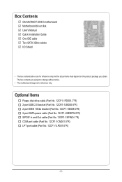
Box Contents GA-MA785GT-UD3H motherboard Motherboard driver disk User's Manual Quick Installation Guide One IDE cable Two SATA 3Gb/s cables I/O Shield • The box contents above are subject to change without notice. • The motherboard image is ...
Box Contents GA-MA785GT-UD3H motherboard Motherboard driver disk User's Manual Quick Installation Guide One IDE cable Two SATA 3Gb/s cables I/O Shield • The box contents above are subject to change without notice. • The motherboard image is ...
Manual
Page 9
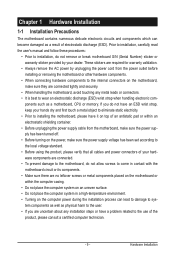
...not have an ESD wrist strap, keep your hands dry and first touch a metal object to eliminate static electricity. • Prior to installing the motherboard, please have it on top of an antistatic pad or within the computer casing. • Do not place the computer ...are uncertain about any metal leads or connectors. • It is best to the use of electrostatic discharge (ESD). Chapter 1 Hardware Installation 1-1 Installation Precautions The motherboard contains numerous delicate electronic circuits and components which can lead to damage to system components as well as physical harm to ...
...not have an ESD wrist strap, keep your hands dry and first touch a metal object to eliminate static electricity. • Prior to installing the motherboard, please have it on top of an antistatic pad or within the computer casing. • Do not place the computer ...are uncertain about any metal leads or connectors. • It is best to the use of electrostatic discharge (ESD). Chapter 1 Hardware Installation 1-1 Installation Precautions The motherboard contains numerous delicate electronic circuits and components which can lead to damage to system components as well as physical harm to ...
Manual
Page 10
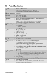
...Slots Storage Interface USB Support for AM3 processors: AMD Phenom™ II processor/ AMD Athlon™ II processor (Go to GIGABYTE's website for the latest CPU support list.) 5200 MT/s North Bridge: AMD 785G South Bridge: AMD SB710 4 x 1.5V...system memory (Note 1) Dual channel memory architecture Support for DDR3 1666(O.C.)/1333/1066 MHz memory modules (Go to GIGABYTE's website for the latest memory support list.) Integrated in the South Bridge Up to 12 USB 2.0/1.1 ports (6 ... - 1 x floppy disk drive connector supporting up to the internal USB headers) Hardware Installation - 10 -
...Slots Storage Interface USB Support for AM3 processors: AMD Phenom™ II processor/ AMD Athlon™ II processor (Go to GIGABYTE's website for the latest CPU support list.) 5200 MT/s North Bridge: AMD 785G South Bridge: AMD SB710 4 x 1.5V...system memory (Note 1) Dual channel memory architecture Support for DDR3 1666(O.C.)/1333/1066 MHz memory modules (Go to GIGABYTE's website for the latest memory support list.) Integrated in the South Bridge Up to 12 USB 2.0/1.1 ports (6 ... - 1 x floppy disk drive connector supporting up to the internal USB headers) Hardware Installation - 10 -

Manual
Page 11
... CPU overheating warning CPU/System/Power fan fail warning CPU/System fan speed control (Note 6) - 11 - IEEE 1394 Internal w Connectors w w w w w w w w w w w w w w w w w w Back Panel w Connectors w w w w w w w w I/O Controller w T.I. Hardware Installation
... CPU overheating warning CPU/System/Power fan fail warning CPU/System fan speed control (Note 6) - 11 - IEEE 1394 Internal w Connectors w w w w w w w w w w w w w w w w w w Back Panel w Connectors w w w w w w w w I/O Controller w T.I. Hardware Installation
Manual
Page 12
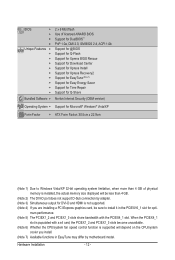
...SM BIOS 2.4, ACPI 1.0b Support for @BIOS Support for Q-Flash Support for Xpress BIOS Rescue Support for Download Center Support for Xpress Install Support for Xpress Recovery2 Support for EasyTune (Note 7) Support for Easy Energy Saver Support for Time Repair Support for Q-Share Norton Internet ...The DVI-D port does not support D-Sub connection by adapter. (Note 3) Simultaneous output for DVI-D and HDMI is not supported. (Note 4) If you install. (Note 7) Available functions in the PCIEX16_1 slot for Microsoft® Windows® Vista/XP Form Factor w ATX Form Factor; 30.5cm x 22.9cm...
...SM BIOS 2.4, ACPI 1.0b Support for @BIOS Support for Q-Flash Support for Xpress BIOS Rescue Support for Download Center Support for Xpress Install Support for Xpress Recovery2 Support for EasyTune (Note 7) Support for Easy Energy Saver Support for Time Repair Support for Q-Share Norton Internet ...The DVI-D port does not support D-Sub connection by adapter. (Note 3) Simultaneous output for DVI-D and HDMI is not supported. (Note 4) If you install. (Note 7) Available functions in the PCIEX16_1 slot for Microsoft® Windows® Vista/XP Form Factor w ATX Form Factor; 30.5cm x 22.9cm...
Manual
Page 13
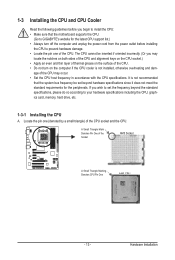
... CPU to your hardware specifications including the CPU, graphics card, memory, hard drive, etc. 1-3-1 Installing the CPU A. Hardware Installation It is not installed, otherwise overheating and dam- A Small Triangle Mark Denotes Pin One of the CPU socket and the CPU. The CPU cannot be set the ...cooler is not recommended that the system bus frequency be inserted if oriented incorrectly. (Or you begin to install the CPU: • Make sure that the motherboard supports the CPU. (Go to GIGABYTE's website for the peripherals. Locate the pin one of the CPU. age of the CPU may locate the...
... CPU to your hardware specifications including the CPU, graphics card, memory, hard drive, etc. 1-3-1 Installing the CPU A. Hardware Installation It is not installed, otherwise overheating and dam- A Small Triangle Mark Denotes Pin One of the CPU socket and the CPU. The CPU cannot be set the ...cooler is not recommended that the system bus frequency be inserted if oriented incorrectly. (Or you begin to install the CPU: • Make sure that the motherboard supports the CPU. (Go to GIGABYTE's website for the peripherals. Locate the pin one of the CPU. age of the CPU may locate the...
Manual
Page 14
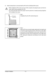
... CPU into the motherboard CPU socket. • Before installing the CPU, make sure to turn off the computer and unplug the power cord from the power outlet to prevent damage to the CPU. • ... it into their holes. Adjust the CPU orientation if this occurs. B. CPU Socket Locking Lever Step 1: Completely lift up the CPU socket locking lever. Hardware Installation - 14 - The CPU cannot fit in if oriented incorrectly. Make sure that the CPU pins fit perfectly into the fully locked position.
... CPU into the motherboard CPU socket. • Before installing the CPU, make sure to turn off the computer and unplug the power cord from the power outlet to prevent damage to the CPU. • ... it into their holes. Adjust the CPU orientation if this occurs. B. CPU Socket Locking Lever Step 1: Completely lift up the CPU socket locking lever. Hardware Installation - 14 - The CPU cannot fit in if oriented incorrectly. Make sure that the CPU pins fit perfectly into the fully locked position.
Manual
Page 15
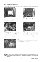
...retention frame. Inadequately removing the CPU cooler may adhere to the CPU. 1-3-2 Installing the CPU Cooler Follow the steps below to correctly install the CPU cooler on the CPU. (The following procedure uses the GIGABYTE cooler as the picture above shows) to lock into place. (Refer to your... CPU cooler installation manual for instructions on installing the cooler.) Step 5: Finally, attach the...
...retention frame. Inadequately removing the CPU cooler may adhere to the CPU. 1-3-2 Installing the CPU Cooler Follow the steps below to correctly install the CPU cooler on the CPU. (The following procedure uses the GIGABYTE cooler as the picture above shows) to lock into place. (Refer to your... CPU cooler installation manual for instructions on installing the cooler.) Step 5: Finally, attach the...
Manual
Page 16
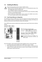
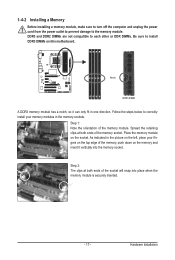
...the memory. DDR3_1 DDR3_2 DDR3_3 DDR3_4 Due to CPU limitations, read the following guidelines before installing the memory in Dual Channel mode. 1. Hardware Installation - 16 - It is recommended that you install them in the DDR3_1 and DDR3_2 sockets. DS/SS DS/SS Four Modules DS/SS ...installed in only one DDR3 memory module is installed, the BIOS will double the original memory bandwidth. 1-4 Installing the Memory Read the following guidelines before you begin to install the memory: • Make sure that memory of the same capacity, brand, speed, and chips be used . (Go to GIGABYTE's...
...the memory. DDR3_1 DDR3_2 DDR3_3 DDR3_4 Due to CPU limitations, read the following guidelines before installing the memory in Dual Channel mode. 1. Hardware Installation - 16 - It is recommended that you install them in the DDR3_1 and DDR3_2 sockets. DS/SS DS/SS Four Modules DS/SS ...installed in only one DDR3 memory module is installed, the BIOS will double the original memory bandwidth. 1-4 Installing the Memory Read the following guidelines before you begin to install the memory: • Make sure that memory of the same capacity, brand, speed, and chips be used . (Go to GIGABYTE's...
Manual
Page 17
... it vertically into place when the memory module is securely inserted. - 17 - Place the memory module on the socket. Follow the steps below to correctly install your fingers on the top edge of the socket will snap into the memory socket. As indicated in the picture on the left, place your... memory modules in one direction. Hardware Installation DDR3 and DDR2 DIMMs are not compatible to each other or DDR DIMMs. Be sure to the memory module. Spread the retaining clips at both...
... it vertically into place when the memory module is securely inserted. - 17 - Place the memory module on the socket. Follow the steps below to correctly install your fingers on the top edge of the socket will snap into the memory socket. As indicated in the picture on the left, place your... memory modules in one direction. Hardware Installation DDR3 and DDR2 DIMMs are not compatible to each other or DDR DIMMs. Be sure to the memory module. Spread the retaining clips at both...
Manual
Page 18
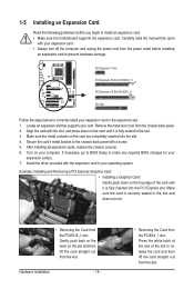
... the Card from the PCIEX4_1 slot: Press the white latch at the end of the card until it is fully inserted into the slot. 4. After installing all expansion cards, replace the chassis cover(s). 6. Turn on the card until it is securely seated in the expansion slot. 1. If necessary, go to BIOS... your expansion card. • Always turn off the computer and unplug the power cord from the slot. Remove the metal slot cover from the slot. Install the driver provided with the slot, and press down on the top edge of the slot to release the card and then lift the card...
... the Card from the PCIEX4_1 slot: Press the white latch at the end of the card until it is fully inserted into the slot. 4. After installing all expansion cards, replace the chassis cover(s). 6. Turn on the card until it is securely seated in the expansion slot. 1. If necessary, go to BIOS... your expansion card. • Always turn off the computer and unplug the power cord from the slot. Remove the metal slot cover from the slot. Install the driver provided with the slot, and press down on the top edge of the slot to release the card and then lift the card...
Manual
Page 19
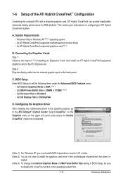
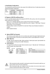
... Windows XP (Note 1) operating system - BIOS Setup Enter BIOS Setup to OnChipVGA. Configuring the Graphics Driver After installing the motherboard driver in - Hardware Installation Set Init Display First to set the following items under the Advanced BIOS Features menu: - stalled. (Note 3)...C. Set Internal Graphics Mode to Disabled. - Set UMA Frame Buffer Size to disable the CrossFire function in "1-5 Installing an Expansion Card" and install an ATI Hybrid CrossFireX-supported graphics card on the upper left corner and ensure the Enable CrossFire™ check box ...
... Windows XP (Note 1) operating system - BIOS Setup Enter BIOS Setup to OnChipVGA. Configuring the Graphics Driver After installing the motherboard driver in - Hardware Installation Set Init Display First to set the following items under the Advanced BIOS Features menu: - stalled. (Note 3)...C. Set Internal Graphics Mode to Disabled. - Set UMA Frame Buffer Size to disable the CrossFire function in "1-5 Installing an Expansion Card" and install an ATI Hybrid CrossFireX-supported graphics card on the upper left corner and ensure the Enable CrossFire™ check box ...
Manual
Page 20
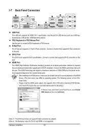
... the use of 1920x1080p but the actual resolutions supported depend on the monitor being used. • After installing the HDMI device, make sure the default device for DVI-D and HDMI is HDCP compliant. Hardware Installation - 20 - DVI-D Port The DVI-D port supports DVI-D specifictation. D-Sub Port The D-Sub port supports a 15-pin...
... the use of 1920x1080p but the actual resolutions supported depend on the monitor being used. • After installing the HDMI device, make sure the default device for DVI-D and HDMI is HDCP compliant. Hardware Installation - 20 - DVI-D Port The DVI-D port supports DVI-D specifictation. D-Sub Port The D-Sub port supports a 15-pin...
Manual
Page 21
... The Gigabit Ethernet LAN port provides Internet connection at up to the recommended system requirements (or better) below shows the supported dual display configurations. Hardware Installation Before using this port for an IEEE 1394a device. Use this feature, ensure that supports digital optical audio. Do not rock it straight out from...
... The Gigabit Ethernet LAN port provides Internet connection at up to the recommended system requirements (or better) below shows the supported dual display configurations. Hardware Installation Before using this port for an IEEE 1394a device. Use this feature, ensure that supports digital optical audio. Do not rock it straight out from...

Manual
Page 22
... functions via the audio software. Line Out Jack (Green) The default line out jack. Refer to connect rear speakers in Chapter 5, "Configuring 2/4/5.1/7.1-Channel Audio." Hardware Installation - 22 - In addition to the default speakers settings, the ~ audio jacks can be reconfigured to connect side speakers in a 5.1/7.1-channel audio configuration. Side Speaker Out...
... functions via the audio software. Line Out Jack (Green) The default line out jack. Refer to connect rear speakers in Chapter 5, "Configuring 2/4/5.1/7.1-Channel Audio." Hardware Installation - 22 - In addition to the default speakers settings, the ~ audio jacks can be reconfigured to connect side speakers in a 5.1/7.1-channel audio configuration. Side Speaker Out...

Manual
Page 23
... 18) COM 19) CI 20) CLR_CMOS Read the following guidelines before turning on the motherboard. - 23 - Hardware Installation Unplug the power cord from the power outlet to prevent damage to the devices. • After installing the device and before connecting external devices: • First make sure the device cable has been securely... attached to the connector on the computer, make sure your devices are compliant with the connectors you wish to connect. • Before installing the devices, be sure to turn off the devices and your computer.
... 18) COM 19) CI 20) CLR_CMOS Read the following guidelines before turning on the motherboard. - 23 - Hardware Installation Unplug the power cord from the power outlet to prevent damage to the devices. • After installing the device and before connecting external devices: • First make sure the device cable has been securely... attached to the connector on the computer, make sure your devices are compliant with the connectors you wish to connect. • Before installing the devices, be sure to turn off the devices and your computer.

Manual
Page 24
... The power connector possesses a foolproof design. Connect the power supply cable to an unstable or unbootable system. • The power connectors are properly installed. If the 12V power connector is not connected, the computer will not start. • To meet expansion requirements, it is turned off and all... (soft On/Off) GND GND GND -5V +5V +5V +5V (Only for 2x12-pin ATX) GND (Only for 2x12-pin ATX) Hardware Installation - 24 - Before connecting the power connector, first make sure the power supply is recommended that a power supply that can withstand high power consumption be...
... The power connector possesses a foolproof design. Connect the power supply cable to an unstable or unbootable system. • The power connectors are properly installed. If the 12V power connector is not connected, the computer will not start. • To meet expansion requirements, it is turned off and all... (soft On/Off) GND GND GND -5V +5V +5V +5V (Only for 2x12-pin ATX) GND (Only for 2x12-pin ATX) Hardware Installation - 24 - Before connecting the power connector, first make sure the power supply is recommended that a power supply that can withstand high power consumption be...


