Manual
Page 1
GA-MA785GPM-UD2H/ GA-MA785GM-UD2H/ GA-MA785GM-US2H AM2+/AM2 socket motherboard for AMD Phenom™ II processor/ AMD Phenom™ processor/ AMD Athlon™ II processor/ AMD Athlon™ processor/ AMD Sempron™ processor User's Manual Rev. 1001 12ME-MA785M2-1001R
GA-MA785GPM-UD2H/ GA-MA785GM-UD2H/ GA-MA785GM-US2H AM2+/AM2 socket motherboard for AMD Phenom™ II processor/ AMD Phenom™ processor/ AMD Athlon™ II processor/ AMD Athlon™ processor/ AMD Sempron™ processor User's Manual Rev. 1001 12ME-MA785M2-1001R
Manual
Page 3
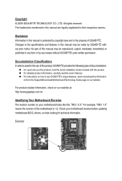
... Documentation Classifications In order to the specifications and features in this manual are legally registered to use of GIGABYTE. For product-related information, check on our website at: http://www.gigabyte.com.tw Identifying Your Motherboard Revision The revision number on how to...their respective owners. For example, "REV: 1.0" means the revision of the motherboard is the property of this manual is protected by GIGABYTE without GIGABYTE's prior written permission. Disclaimer Information in any form or by any means without prior notice. For instructions on your...
... Documentation Classifications In order to the specifications and features in this manual are legally registered to use of GIGABYTE. For product-related information, check on our website at: http://www.gigabyte.com.tw Identifying Your Motherboard Revision The revision number on how to...their respective owners. For example, "REV: 1.0" means the revision of the motherboard is the property of this manual is protected by GIGABYTE without GIGABYTE's prior written permission. Disclaimer Information in any form or by any means without prior notice. For instructions on your...
Manual
Page 5
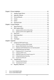
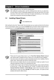
k Only for GA-MA785GPM-UD2H. Chapter 3 Drivers Installation 61 3-1 Installing Chipset Drivers 61 3-2 Application Software 62 3-3 Technical Manuals 62 3-4 Contact...63 3-5 System...63 3-6 Download Center 64 Chapter 4 Unique Features 65 4-1 Xpress Recovery2 65 4-2 BIOS Update Utilities 68 4-2-1 Updating the BIOS with the Q-Flash ... Functionjk 92 5-2-4 Configuring Microphone Recording 93 5-2-5 Using the Sound Recorder 95 5-3 Troubleshooting 96 5-3-1 Frequently Asked Questions 96 5-3-2 Troubleshooting Procedure 97 5-4 Regulatory Statements 99 j Only for GA-MA785GM-UD2H. - 5 -
k Only for GA-MA785GPM-UD2H. Chapter 3 Drivers Installation 61 3-1 Installing Chipset Drivers 61 3-2 Application Software 62 3-3 Technical Manuals 62 3-4 Contact...63 3-5 System...63 3-6 Download Center 64 Chapter 4 Unique Features 65 4-1 Xpress Recovery2 65 4-2 BIOS Update Utilities 68 4-2-1 Updating the BIOS with the Q-Flash ... Functionjk 92 5-2-4 Configuring Microphone Recording 93 5-2-5 Using the Sound Recorder 95 5-3 Troubleshooting 96 5-3-1 Frequently Asked Questions 96 5-3-2 Troubleshooting Procedure 97 5-4 Regulatory Statements 99 j Only for GA-MA785GM-UD2H. - 5 -
Manual
Page 6
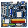
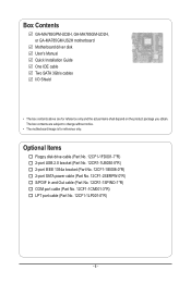
The box contents are for reference only. Box Contents GA-MA785GPM-UD2H, GA-MA785GM-UD2H, or GA-MA785GM-US2H motherboard Motherboard driver disk User's Manual Quick Installation Guide One IDE cable Two SATA 3Gb/s cables I/O Shield • The box contents above are subject to change without notice. • The motherboard ...
The box contents are for reference only. Box Contents GA-MA785GPM-UD2H, GA-MA785GM-UD2H, or GA-MA785GM-US2H motherboard Motherboard driver disk User's Manual Quick Installation Guide One IDE cable Two SATA 3Gb/s cables I/O Shield • The box contents above are subject to change without notice. • The motherboard ...
Manual
Page 9
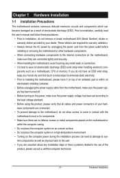
... installation process can become damaged as a result of electrostatic discharge (ESD). ponents such as a motherboard, CPU or memory. Prior to installation, carefully read the user's manual and follow these procedures: • Prior to installation, do not remove or break motherboard S/N (Serial Number) sticker or warranty sticker provided by unplugging the power...
... installation process can become damaged as a result of electrostatic discharge (ESD). ponents such as a motherboard, CPU or memory. Prior to installation, carefully read the user's manual and follow these procedures: • Prior to installation, do not remove or break motherboard S/N (Serial Number) sticker or warranty sticker provided by unplugging the power...

Manual
Page 15
... the steps below to correctly install the CPU cooler on the CPU. (The following procedure uses the GIGABYTE cooler as the picture above shows) to lock into place. (Refer to your CPU cooler installation manual for instructions on the CPU. On the other side,push straight down on the the CPU cooler...
... the steps below to correctly install the CPU cooler on the CPU. (The following procedure uses the GIGABYTE cooler as the picture above shows) to lock into place. (Refer to your CPU cooler installation manual for instructions on the CPU. On the other side,push straight down on the the CPU cooler...
Manual
Page 18
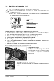
... an expansion slot that came with the slot, and press down on the card are completely inserted into the PCI Express slot. Carefully read the manual that supports your expansion card in your expansion card. • Always turn off the computer and unplug the power cord from the PCIEX16_1 slot: Gently...
... an expansion slot that came with the slot, and press down on the card are completely inserted into the PCI Express slot. Carefully read the manual that supports your expansion card in your expansion card. • Always turn off the computer and unplug the power cord from the PCIEX16_1 slot: Gently...
Manual
Page 33
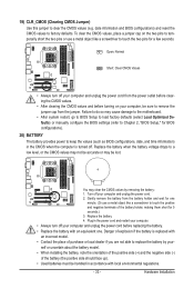
... accurate or may cause damage to the motherboard. • After system restart, go to BIOS Setup to load factory defaults (select Load Optimized Defaults) or manually configure the BIOS settings (refer to Chapter 2, "BIOS Setup," for BIOS configurations). 20) BATTERY The battery provides power to keep the values (such as BIOS...
... accurate or may cause damage to the motherboard. • After system restart, go to BIOS Setup to load factory defaults (select Load Optimized Defaults) or manually configure the BIOS settings (refer to Chapter 2, "BIOS Setup," for BIOS configurations). 20) BATTERY The battery provides power to keep the values (such as BIOS...
Manual
Page 39
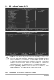
... Control SouthBridge Volt Control SidePort Mem Volt Control [Press Enter] [Auto] [Auto] [Auto] [Auto] 200 [Auto] [Disabled] 500 [Auto] x4.00 800Mhz [Unganged] [Press Enter] [Manual] [Normal] [Normal] [Normal] [Normal] Item Help Menu Level Move Enter: Select F5: Previous Values +/-/PU/PD: Value F10: Save F6: Fail-Safe Defaults ESC...
... Control SouthBridge Volt Control SidePort Mem Volt Control [Press Enter] [Auto] [Auto] [Auto] [Auto] 200 [Auto] [Disabled] 500 [Auto] x4.00 800Mhz [Unganged] [Press Enter] [Manual] [Normal] [Normal] [Normal] [Normal] Item Help Menu Level Move Enter: Select F5: Previous Values +/-/PU/PD: Value F10: Save F6: Fail-Safe Defaults ESC...
Manual
Page 40
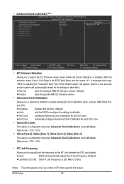
... Link Frequency. (Default) 200 MHz~2.0 GHz Sets HT Link Frequency to 200 MHz~2.0 GHz. (Note) This item appears only if you to determine whether to manually set to defaults. Disabled Disables this feature. Options are : -12%~+12%. HT Link Frequency Allows you to enable Advanced Clock Calibration when using an AMD...
... Link Frequency. (Default) 200 MHz~2.0 GHz Sets HT Link Frequency to 200 MHz~2.0 GHz. (Note) This item appears only if you to determine whether to manually set to defaults. Disabled Disables this feature. Options are : -12%~+12%. HT Link Frequency Allows you to enable Advanced Clock Calibration when using an AMD...
Manual
Page 41
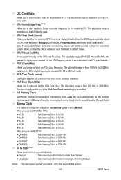
...Set Memory Clock is dependent on the CPU being used . Unganged Sets memory control mode to DDR 800. Auto (default) allows the BIOS to manually set to standard 100 MHz. (Default: Auto) VGA Core Clock control Enables or disables the control of CPU host clock. Auto sets the ...PCIe clock frequency to Manual. Set Memory Clock Determines whether to automatically adjust the CPU host frequency. DCTs Mode (Note) Allows you to X3.33. BIOS Setup The ...
...Set Memory Clock is dependent on the CPU being used . Unganged Sets memory control mode to DDR 800. Auto (default) allows the BIOS to manually set to standard 100 MHz. (Default: Auto) VGA Core Clock control Enables or disables the control of CPU host clock. Auto sets the ...PCIe clock frequency to Manual. Set Memory Clock Determines whether to automatically adjust the CPU host frequency. DCTs Mode (Note) Allows you to X3.33. BIOS Setup The ...

Manual
Page 42
...default), 5T~18T. 1T/2T Command Timing Options are : Auto (default), 75ns, 105ns, 127.5ns, 195ns, 327.5ns. Write Recovery Time Options are : Auto (default), Manual. Options are : Auto (default), 3T~6T. Trfc2 for DIMM3 Options are : Auto (default), 1T, 2T. Trfc3 for DIMM4 x Write Recovery Time x Precharge Time x Row... F5: Previous Values +/-/PU/PD: Value F10: Save F6: Fail-Safe Defaults ESC: Exit F1: General Help F7: Optimized Defaults DDRII Timing Items Manual allows all DDR2 Timing items below to be configurable. CAS# latency Options are: Auto (default), 3T~6T.
...default), 5T~18T. 1T/2T Command Timing Options are : Auto (default), 75ns, 105ns, 127.5ns, 195ns, 327.5ns. Write Recovery Time Options are : Auto (default), Manual. Options are : Auto (default), 3T~6T. Trfc2 for DIMM3 Options are : Auto (default), 1T, 2T. Trfc3 for DIMM4 x Write Recovery Time x Precharge Time x Row... F5: Previous Values +/-/PU/PD: Value F10: Save F6: Fail-Safe Defaults ESC: Exit F1: General Help F7: Optimized Defaults DDRII Timing Items Manual allows all DDR2 Timing items below to be configurable. CAS# latency Options are: Auto (default), 3T~6T.
Manual
Page 43
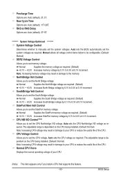
... 2T~5T. ******** System Voltage Optimized ******** System Voltage Control Determines whether to set the system voltages. SouthBridge Volt Control Allows you to manually set the North Bridge voltage. Normal CPU Vcore Displays the normal operating voltage of your CPU (Note) This item appears only if you... to set the CPU Northbridge VID voltage. Precharge Time Options are : Auto (default), 11T~26T. Manual allows all voltage control items below to be configurable. (Default: Manual) DDR2 Voltage Control Allows you to the memory. SidePort Mem Volt Control Allows you to your CPU ...
... 2T~5T. ******** System Voltage Optimized ******** System Voltage Control Determines whether to set the system voltages. SouthBridge Volt Control Allows you to manually set the North Bridge voltage. Normal CPU Vcore Displays the normal operating voltage of your CPU (Note) This item appears only if you... to set the CPU Northbridge VID voltage. Precharge Time Options are : Auto (default), 11T~26T. Manual allows all voltage control items below to be configurable. (Default: Manual) DDR2 Voltage Control Allows you to the memory. SidePort Mem Volt Control Allows you to your CPU ...

Manual
Page 45
.../3.5". Precomp Write precompensation cylinder. Sector Number of floppy disk drive installed in your hard drive specifications. Halt On Allows you wish to enter the parameters manually, refer to specify whether the installed floppy disk drive is 3-mode floppy disk drive, a Japanese standard floppy disk drive.
.../3.5". Precomp Write precompensation cylinder. Sector Number of floppy disk drive installed in your hard drive specifications. Halt On Allows you wish to enter the parameters manually, refer to specify whether the installed floppy disk drive is 3-mode floppy disk drive, a Japanese standard floppy disk drive.
Manual
Page 61
...; For USB 2.0 driver support under the Windows XP operating system, please install the Windows XP Service Pack 1 or later. Or click Install Single Items to manually select the drivers you wish to do so may affect the driver installation. • Some device drivers will restart your system. You can click the...
...; For USB 2.0 driver support under the Windows XP operating system, please install the Windows XP Service Pack 1 or later. Or click Install Single Items to manually select the drivers you wish to do so may affect the driver installation. • Some device drivers will restart your system. You can click the...
Manual
Page 62
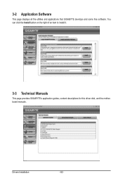
Drivers Installation - 62 - You can click the Install button on the right of an item to install it. 3-3 Technical Manuals This page provides GIGABYTE's application guides, content descriptions for this driver disk, and the motherboard manuals. 3-2 Application Software This page displays all the utilities and applications that GIGABYTE develops and some free software.
Drivers Installation - 62 - You can click the Install button on the right of an item to install it. 3-3 Technical Manuals This page provides GIGABYTE's application guides, content descriptions for this driver disk, and the motherboard manuals. 3-2 Application Software This page displays all the utilities and applications that GIGABYTE develops and some free software.

Manual
Page 68
...with caution. Award Modular BIOS v6.00PG, An Energy Star Ally Copyright (C) 1984-2009, Award Software, Inc. GA-MA785GPM-UD2H E3c . . . . : BIOS Setup : XpressRecovery2 : Boot Menu : Qflash 06/05/2009-...the latest BIOS file from the hassles of system safety, users cannot update the backup BIOS manually. Unique Features - 68 - Additionally, this motherboard features the DualBIOS™ design, which... system operation. M785GPD2.F1) to enter operating systems like MS-DOS or Window first. GIGABYTE Q-Flash and @BIOS are easy-to access Q-Flash. For the sake of going through...
...with caution. Award Modular BIOS v6.00PG, An Energy Star Ally Copyright (C) 1984-2009, Award Software, Inc. GA-MA785GPM-UD2H E3c . . . . : BIOS Setup : XpressRecovery2 : Boot Menu : Qflash 06/05/2009-...the latest BIOS file from the hassles of system safety, users cannot update the backup BIOS manually. Unique Features - 68 - Additionally, this motherboard features the DualBIOS™ design, which... system operation. M785GPD2.F1) to enter operating systems like MS-DOS or Window first. GIGABYTE Q-Flash and @BIOS are easy-to access Q-Flash. For the sake of going through...
Manual
Page 71
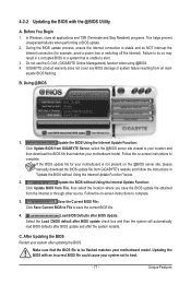
...connection (for your motherboard is unable to boot. - 71 - Follow the on the @BIOS server site, please manually download the BIOS update file from GIGABYTE's website and follow the instructions in "Update the BIOS without Using the Internet Update Function: Click Update BIOS from ...then download the BIOS file that is not present on -screen instructions to complete. 3. Before You Begin 1. Do not use the G.O.M. (GIGABYTE Online Management) function when using @BIOS. 4. Unique Features 4-2-2 Updating the BIOS with an incorrect BIOS file could cause your system after the ...
...connection (for your motherboard is unable to boot. - 71 - Follow the on the @BIOS server site, please manually download the BIOS update file from GIGABYTE's website and follow the instructions in "Update the BIOS without Using the Internet Update Function: Click Update BIOS from ...then download the BIOS file that is not present on -screen instructions to complete. 3. Before You Begin 1. Do not use the G.O.M. (GIGABYTE Online Management) function when using @BIOS. 4. Unique Features 4-2-2 Updating the BIOS with an incorrect BIOS file could cause your system after the ...
Manual
Page 80
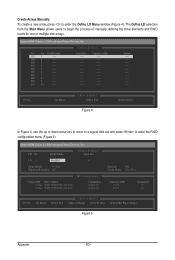
...Select In Figure 4, use the up or down arrow key to move to a logical disk set and press to begin the process of manually defining the drive elements and RAID levels for one or multiple disk arrays. LD 6 ---- Option ROM Utility (c) 2008 Advanced Micro Devices, ...10 ---- LD 4 ---- LD 9 ---- LD No RAID Mode [ Define LD Menu ] Total Drv LD 1 RAID 0 0 Stripe Block: 64 KB Gigabyte Boundary: ON [ Drives Assignments ] Channel:ID Drive Model 1:Mas WDC WD800JD-22LSA0 2:Mas WDC WD800JD-22LSA0 Capabilities SATA 3G SATA 3G Fast Init: ON Cache...
...Select In Figure 4, use the up or down arrow key to move to a logical disk set and press to begin the process of manually defining the drive elements and RAID levels for one or multiple disk arrays. LD 6 ---- Option ROM Utility (c) 2008 Advanced Micro Devices, ...10 ---- LD 4 ---- LD 9 ---- LD No RAID Mode [ Define LD Menu ] Total Drv LD 1 RAID 0 0 Stripe Block: 64 KB Gigabyte Boundary: ON [ Drives Assignments ] Channel:ID Drive Model 1:Mas WDC WD800JD-22LSA0 2:Mas WDC WD800JD-22LSA0 Capabilities SATA 3G SATA 3G Fast Init: ON Cache...
Manual
Page 88
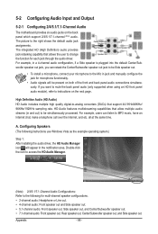
... the icon to access the HD Audio Manager. (Note) 2/4/5.1/7.1-Channel Audio Configurations: Refer to -analog converters (DACs) that allow multiple audio streams (in jack and manually configure the jack for microphone functionality. • Audio signals will appear in a 4-channel audio configuration, if a Side speaker is plugged into the default Center/Sub...
... the icon to access the HD Audio Manager. (Note) 2/4/5.1/7.1-Channel Audio Configurations: Refer to -analog converters (DACs) that allow multiple audio streams (in jack and manually configure the jack for microphone functionality. • Audio signals will appear in a 4-channel audio configuration, if a Side speaker is plugged into the default Center/Sub...


