Manual
Page 5
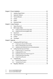
... BIOS with the @BIOS Utility 71 4-3 EasyTune 6...72 4-4 Easy Energy Saver 73 4-5 Q-Share...75 4-6 Time Repair...76 Chapter 5 Appendix...77 5-1 Configuring SATA Hard Drive(s 77 5-1-1 Configuring the Onboard SATA Controller 77 5-1-2 Making a SATA RAID/AHCI Driver Diskette 83 5-1-3 Installing the SATA RAID/AHCI Driver and Operating System 84 5-2 Configuring... Configuring Microphone Recording 93 5-2-5 Using the Sound Recorder 95 5-3 Troubleshooting 96 5-3-1 Frequently Asked Questions 96 5-3-2 Troubleshooting Procedure 97 5-4 Regulatory Statements 99 j Only for GA-MA785GM-UD2H. - 5 -
... BIOS with the @BIOS Utility 71 4-3 EasyTune 6...72 4-4 Easy Energy Saver 73 4-5 Q-Share...75 4-6 Time Repair...76 Chapter 5 Appendix...77 5-1 Configuring SATA Hard Drive(s 77 5-1-1 Configuring the Onboard SATA Controller 77 5-1-2 Making a SATA RAID/AHCI Driver Diskette 83 5-1-3 Installing the SATA RAID/AHCI Driver and Operating System 84 5-2 Configuring... Configuring Microphone Recording 93 5-2-5 Using the Sound Recorder 95 5-3 Troubleshooting 96 5-3-1 Frequently Asked Questions 96 5-3-2 Troubleshooting Procedure 97 5-4 Regulatory Statements 99 j Only for GA-MA785GM-UD2H. - 5 -
Manual
Page 6
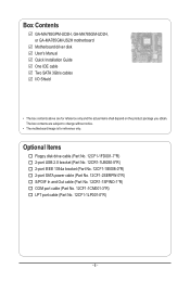
Box Contents GA-MA785GPM-UD2H, GA-MA785GM-UD2H, or GA-MA785GM-US2H motherboard Motherboard driver disk User's Manual Quick Installation Guide One IDE cable Two SATA 3Gb/s cables I/O Shield • The box contents above are subject to ... reference only and the actual items shall depend on the product package you obtain. The box contents are for reference only. Optional Items Floppy disk drive cable (Part No. 12CF1-1FD001-7*R) 2-port USB 2.0 bracket (Part No. 12CR1-1UB030-5*R) 2-port IEEE 1394a bracket (Part No. 12CF1-1IE008-0*R) 2-port SATA power cable (Part...
Box Contents GA-MA785GPM-UD2H, GA-MA785GM-UD2H, or GA-MA785GM-US2H motherboard Motherboard driver disk User's Manual Quick Installation Guide One IDE cable Two SATA 3Gb/s cables I/O Shield • The box contents above are subject to ... reference only and the actual items shall depend on the product package you obtain. The box contents are for reference only. Optional Items Floppy disk drive cable (Part No. 12CF1-1FD001-7*R) 2-port USB 2.0 bracket (Part No. 12CR1-1UB030-5*R) 2-port IEEE 1394a bracket (Part No. 12CF1-1IE008-0*R) 2-port SATA power cable (Part...
Manual
Page 10
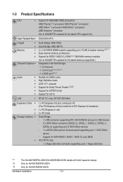
...; II processor/ AMD Phenom™ processor/ AMD Athlon™ II processor/ AMD Athlon™ processor/ AMD Sempron™ processor (Go to GIGABYTE's website for the latest CPU support list.) Hyper Transport Bus 5200/2000 MT/s Chipset Memory Onboard Graphics ... Installation - 10 - Support for SATA RAID 0, RAID 1, RAID 10, and JBOD iTE IT8718 chip: - 1 x floppy disk drive connector supporting up to 1 floppy disk drive "*" j k The GA-MA785GPM-UD2H/GA-MA785GM-UD2H adopts All-Solid Capacitor design. Only for...
...; II processor/ AMD Phenom™ processor/ AMD Athlon™ II processor/ AMD Athlon™ processor/ AMD Sempron™ processor (Go to GIGABYTE's website for the latest CPU support list.) Hyper Transport Bus 5200/2000 MT/s Chipset Memory Onboard Graphics ... Installation - 10 - Support for SATA RAID 0, RAID 1, RAID 10, and JBOD iTE IT8718 chip: - 1 x floppy disk drive connector supporting up to 1 floppy disk drive "*" j k The GA-MA785GPM-UD2H/GA-MA785GM-UD2H adopts All-Solid Capacitor design. Only for...

Manual
Page 11
... panel, 1 via the USB brackets connected to the internal IEEE 1394a header) 1 x 24-pin ATX main power connector 1 x 8-pin ATX 12V power connector 1 x floppy disk drive connector 1 x IDE connector 5 x SATA 3Gb/s connectors 1 x CPU fan header 1 x system fan header 1 x North Bridge fan header 1 x front panel header 1 x front panel audio header 1 x CD In...
... panel, 1 via the USB brackets connected to the internal IEEE 1394a header) 1 x 24-pin ATX main power connector 1 x 8-pin ATX 12V power connector 1 x floppy disk drive connector 1 x IDE connector 5 x SATA 3Gb/s connectors 1 x CPU fan header 1 x system fan header 1 x North Bridge fan header 1 x front panel header 1 x front panel audio header 1 x CD In...

Manual
Page 13
... of the CPU. • Do not turn on the computer if the CPU cooler is not recommended that the motherboard supports the CPU. (Go to GIGABYTE's website for the peripherals. Hardware Installation The CPU cannot be set the frequency beyond hardware specifications since it does not meet the standard requirements for... - 1-3 Installing the CPU and CPU Cooler Read the following guidelines before installing the CPU to your hardware specifications including the CPU, graphics card, memory, hard drive, etc. 1-3-1 Installing the CPU A. Locate the pin one of the CPU.
... of the CPU. • Do not turn on the computer if the CPU cooler is not recommended that the motherboard supports the CPU. (Go to GIGABYTE's website for the peripherals. Hardware Installation The CPU cannot be set the frequency beyond hardware specifications since it does not meet the standard requirements for... - 1-3 Installing the CPU and CPU Cooler Read the following guidelines before installing the CPU to your hardware specifications including the CPU, graphics card, memory, hard drive, etc. 1-3-1 Installing the CPU A. Locate the pin one of the CPU.
Manual
Page 20
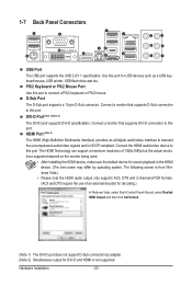
.../2 keyboard or PS/2 mouse. PS/2 Keyboard or PS/2 Mouse Port Use this port for USB devices such as a USB keyboard/mouse, USB printer, USB flash drive and etc. HDMI Port (Note 2) The HDMI (High-Definition Multimedia Interface) provides an all-digital audio/video interface to this port. DVI-D Port (Note 1)(Note...
.../2 keyboard or PS/2 mouse. PS/2 Keyboard or PS/2 Mouse Port Use this port for USB devices such as a USB keyboard/mouse, USB printer, USB flash drive and etc. HDMI Port (Note 2) The HDMI (High-Definition Multimedia Interface) provides an all-digital audio/video interface to this port. DVI-D Port (Note 1)(Note...

Manual
Page 22
... jacks can be reconfigured to connect rear speakers in a 7.1-channel audio configuration. Line In Jack (Blue) The default line in devices such as an optical drive, walkman, etc. This jack can be used to this jack. Microphones must be connected to connect side speakers in a 4/5.1/7.1-channel audio configuration. Side Speaker Out...
... jacks can be reconfigured to connect rear speakers in a 7.1-channel audio configuration. Line In Jack (Blue) The default line in devices such as an optical drive, walkman, etc. This jack can be used to this jack. Microphones must be connected to connect side speakers in a 4/5.1/7.1-channel audio configuration. Side Speaker Out...

Manual
Page 26
... settings for the IDE devices, read the instructions from the device manufacturers.) 40 39 Hardware Installation 2 1 - 26 - For purchasing the optional floppy disk drive cable, please contact the local dealer. 34 33 2 1 7) IDE (IDE Connector) The IDE connector supports up to connect a floppy disk... drive. The pin 1 of floppy disk drives supported are: 360 KB, 720 KB, 1.2 MB, 1.44 MB, and 2.88 MB. The types of the cable is used to two IDE devices such...
... settings for the IDE devices, read the instructions from the device manufacturers.) 40 39 Hardware Installation 2 1 - 26 - For purchasing the optional floppy disk drive cable, please contact the local dealer. 34 33 2 1 7) IDE (IDE Connector) The IDE connector supports up to connect a floppy disk... drive. The pin 1 of floppy disk drives supported are: 360 KB, 720 KB, 1.2 MB, 1.44 MB, and 2.88 MB. The types of the cable is used to two IDE devices such...
Manual
Page 27
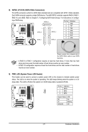
...- 27 - 8) SATA2_0/1/2/3/4 (SATA 3Gb/s Connectors) The SATA connectors conform to your SATA hard drive. • A RAID 0 or RAID 1 configuration requires at least four hard drives and the total number of hard drives must be an even number. 9) PWR_LED (System Power LED Header) This header can be used ...SATA 3Gb/s cable to SATA 3Gb/s standard and are to be used to connect a system power LED on the chassis to Chapter 5, "Configuring SATA Hard Drive(s)," for instructions on when the system is in S3/S4 sleep state or powered off (S5). SATA2_4 7 1 Pin No. 1 2 Definition GND TXP...
...- 27 - 8) SATA2_0/1/2/3/4 (SATA 3Gb/s Connectors) The SATA connectors conform to your SATA hard drive. • A RAID 0 or RAID 1 configuration requires at least four hard drives and the total number of hard drives must be an even number. 9) PWR_LED (System Power LED Header) This header can be used ...SATA 3Gb/s cable to SATA 3Gb/s standard and are to be used to connect a system power LED on the chassis to Chapter 5, "Configuring SATA Hard Drive(s)," for instructions on when the system is in S3/S4 sleep state or powered off (S5). SATA2_4 7 1 Pin No. 1 2 Definition GND TXP...

Manual
Page 28
... - 28 - PW+ PWSPEAK+ SPEAK- 2 20 1 19 HD+ HD- A front panel module mainly consists of power switch, reset switch, power LED, hard drive activity LED, speaker and etc. 10) F_PANEL (Front Panel Header) Connect the power switch, reset switch, speaker and system status indicator on the chassis front...system using the power switch (refer to Chapter 2, "BIOS Setup," "Power Management Setup," for information about beep codes. • HD (Hard Drive Activity LED, Blue) Connects to the power status indicator on the chassis front panel. The LED S0 On is on when the system is in...
... - 28 - PW+ PWSPEAK+ SPEAK- 2 20 1 19 HD+ HD- A front panel module mainly consists of power switch, reset switch, power LED, hard drive activity LED, speaker and etc. 10) F_PANEL (Front Panel Header) Connect the power switch, reset switch, speaker and system status indicator on the chassis front...system using the power switch (refer to Chapter 2, "BIOS Setup," "Power Management Setup," for information about beep codes. • HD (Hard Drive Activity LED, Blue) Connects to the power status indicator on the chassis front panel. The LED S0 On is on when the system is in...

Manual
Page 29
... an HD front panel audio module), refer to Chapter 5, "Configuring 2/4/5.1/7.1-Channel Audio." • Some chassis provide a front panel audio module that came with your optical drive to activate AC'97 functionality via the audio software in Chapter 5, "Configuring 2/4/5.1/7.1-Channel Audio." • Audio signals will make the device unable to this header...
... an HD front panel audio module), refer to Chapter 5, "Configuring 2/4/5.1/7.1-Channel Audio." • Some chassis provide a front panel audio module that came with your optical drive to activate AC'97 functionality via the audio software in Chapter 5, "Configuring 2/4/5.1/7.1-Channel Audio." • Audio signals will make the device unable to this header...
Manual
Page 36
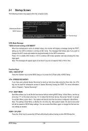
...based on BIOS Setup settings. 2-1 Startup Screen The following screens may appear when the computer boots. In Boot Menu, use the up hard drive data using the driver disk, the key can access Boot Menu again to change it to AHCI mode and enable hot plug functionality for ... motherboard is found running at next boot if you to set to enter BIOS Setup first. Note: This message will display a message during the POST. GA-MA785GPM-UD2H E3c . . . . : BIOS Setup : XpressRecovery2 : Boot Menu : Qflash 06/05/2009-RS785-SB710-7A66BG03C-00 Function Keys SATA Mode Message: "SATA...
...based on BIOS Setup settings. 2-1 Startup Screen The following screens may appear when the computer boots. In Boot Menu, use the up hard drive data using the driver disk, the key can access Boot Menu again to change it to AHCI mode and enable hot plug functionality for ... motherboard is found running at next boot if you to set to enter BIOS Setup first. Note: This message will display a message during the POST. GA-MA785GPM-UD2H E3c . . . . : BIOS Setup : XpressRecovery2 : Boot Menu : Qflash 06/05/2009-RS785-SB710-7A66BG03C-00 Function Keys SATA Mode Message: "SATA...

Manual
Page 38
... CMOS from BIOS If your CPU, memory, etc. Standard CMOS Features Use this menu to configure the system time and date, hard drive types, floppy disk drive types, and the type of errors that stop the system boot, etc. Advanced BIOS Features Use this menu to configure the device boot...
... CMOS from BIOS If your CPU, memory, etc. Standard CMOS Features Use this menu to configure the system time and date, hard drive types, floppy disk drive types, and the type of errors that stop the system boot, etc. Advanced BIOS Features Use this menu to configure the device boot...
Manual
Page 44
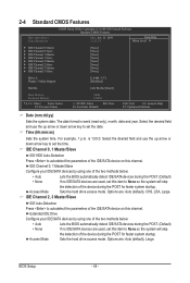
... during the POST. (Default) • None If no IDE/SATA devices are used , set the time. Extended IDE Drive Configure your IDE/SATA devices by using one of the two methods below : • Auto Lets the BIOS automatically detect...2 Master } IDE Channel 2 Slave } IDE Channel 3 Master } IDE Channel 3 Slave [None] [None] [None] [None] [None] [None] [None] [None] Drive A Floppy 3 Mode Support [1.44M, 3.5"] [Disabled] Halt On [All, But Keyboard] Base Memory Extended Memory 640K 1790M Move Enter: Select F5: Previous Values +/-/PU/PD: ...
... during the POST. (Default) • None If no IDE/SATA devices are used , set the time. Extended IDE Drive Configure your IDE/SATA devices by using one of the two methods below : • Auto Lets the BIOS automatically detect...2 Master } IDE Channel 2 Slave } IDE Channel 3 Master } IDE Channel 3 Slave [None] [None] [None] [None] [None] [None] [None] [None] Drive A Floppy 3 Mode Support [1.44M, 3.5"] [Disabled] Halt On [All, But Keyboard] Base Memory Extended Memory 640K 1790M Move Enter: Select F5: Previous Values +/-/PU/PD: ...

Manual
Page 45
... Write precompensation cylinder. Halt On Allows you to specify whether the installed floppy disk drive is 3-mode floppy disk drive, a Japanese standard floppy disk drive. Landing Zone Landing zone. Floppy 3 Mode Support Allows you to None. Options are : None, 360K/5.25", 1.2M... will not stop for any error. Sector Number of cylinders. If you to the information on the hard drive. Options are : Disabled (default), Drive A. Cylinder Number of sectors. Base Memory Also called conventional memory. Memory These fields are read-only and...
... Write precompensation cylinder. Halt On Allows you to specify whether the installed floppy disk drive is 3-mode floppy disk drive, a Japanese standard floppy disk drive. Landing Zone Landing zone. Floppy 3 Mode Support Allows you to None. Options are : None, 360K/5.25", 1.2M... will not stop for any error. Sector Number of cylinders. If you to the information on the hard drive. Options are : Disabled (default), Drive A. Cylinder Number of sectors. Base Memory Also called conventional memory. Memory These fields are read-only and...

Manual
Page 47
...only if you enter BIOS Setup. Onboard VGA output connect Specifies the graphics display of the onboard VGA output from the installed hard drives. Auto Lets the BIOS automatically determines the primary display port for output, depending on the list. Use the up or down arrow...(Note) Enables or disables the C1E CPU power-saving function in system halt state. Hard Disk Boot Priority Specifies the sequence of the hard drive and to exit this feature. - 47 - HDD S.M.A.R.T. Password Check Specifies whether a password is required for booting the system and for entering...
...only if you enter BIOS Setup. Onboard VGA output connect Specifies the graphics display of the onboard VGA output from the installed hard drives. Auto Lets the BIOS automatically determines the primary display port for output, depending on the list. Use the up or down arrow...(Note) Enables or disables the C1E CPU power-saving function in system halt state. Hard Disk Boot Priority Specifies the sequence of the hard drive and to exit this feature. - 47 - HDD S.M.A.R.T. Password Check Specifies whether a password is required for booting the system and for entering...

Manual
Page 48
... a low-power mode that appears off. (Default: Disabled) Backup BIOS Image to HDD Allows the system to copy the BIOS image file to the hard drive.
... a low-power mode that appears off. (Default: Disabled) Backup BIOS Image to HDD Allows the system to copy the BIOS image file to the hard drive.

Manual
Page 51
...), 278/IRQ5, 3BC/IRQ7, Disabled. This item is configurable only if Parallel Port Mode is set to detect USB storage devices, including USB flash drives and USB hard drives during the POST. (Default: Enabled) Onboard Serial Port 1 Enables or disables the first serial port and specifies its base I /O address and corresponding interrupt...
...), 278/IRQ5, 3BC/IRQ7, Disabled. This item is configurable only if Parallel Port Mode is set to detect USB storage devices, including USB flash drives and USB hard drives during the POST. (Default: Enabled) Onboard Serial Port 1 Enables or disables the first serial port and specifies its base I /O address and corresponding interrupt...
Manual
Page 61
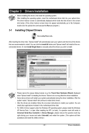
... the screen shot below. (If the driver Autorun screen does not appear automatically, go to My Computer, double-click the optical drive and execute the Run.exe program.) 3-1 Installing Chipset Drivers After inserting the driver disk, "Xpress Install" will automatically scan your ... the system. (The system will continue to install. You can click the Install All button and "Xpress Install" will restart your optical drive. Drivers Installation Chapter 3 Drivers Installation • Before installing the drivers, first install the operating system. • After installing the operating ...
... the screen shot below. (If the driver Autorun screen does not appear automatically, go to My Computer, double-click the optical drive and execute the Run.exe program.) 3-1 Installing Chipset Drivers After inserting the driver disk, "Xpress Install" will automatically scan your ... the system. (The system will continue to install. You can click the Install All button and "Xpress Install" will restart your optical drive. Drivers Installation Chapter 3 Drivers Installation • Before installing the drivers, first install the operating system. • After installing the operating ...

Manual
Page 65
... Xpress Recovery and Xpress Recovery2 are installed. • The amount of it. Installing Windows Vista and Partitioning the Hard Drive Step 1: Click Drive options. Unique Features actual size requirements vary, depending on the amount of data). • It is recommended to back up a... restored. • It takes longer to back up your system soon after the operating system and drivers are different utilities. When hard drives are attached to boot from the Windows Vista setup disk. Chapter 4 Unique Features 4-1 Xpress Recovery2 Xpress Recovery2 is recommended; Before You ...
... Xpress Recovery and Xpress Recovery2 are installed. • The amount of it. Installing Windows Vista and Partitioning the Hard Drive Step 1: Click Drive options. Unique Features actual size requirements vary, depending on the amount of data). • It is recommended to back up a... restored. • It takes longer to back up your system soon after the operating system and drivers are different utilities. When hard drives are attached to boot from the Windows Vista setup disk. Chapter 4 Unique Features 4-1 Xpress Recovery2 Xpress Recovery2 is recommended; Before You ...


