Manual
Page 4
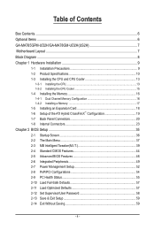
Table of Contents Box Contents...6 Optional Items...6 GA-MA785GPM-UD2H/GA-MA78GM-UD2H(US2H 7 Motherboard Layout...7 Block Diagram...8 Chapter 1 Hardware Installation 9 1-1 Installation Precautions 9 1-2 Product Specifications 10 1-3 Installing the CPU and CPU Cooler 13 1-3-1 Installing the CPU 13 1-3-2 Installing the CPU Cooler 15 1-4 Installing the Memory 16 1-4-1 Dual Channel Memory Configuration 16 1-4-2 Installing a Memory 17 1-5 Installing an Expansion Card...
Table of Contents Box Contents...6 Optional Items...6 GA-MA785GPM-UD2H/GA-MA78GM-UD2H(US2H 7 Motherboard Layout...7 Block Diagram...8 Chapter 1 Hardware Installation 9 1-1 Installation Precautions 9 1-2 Product Specifications 10 1-3 Installing the CPU and CPU Cooler 13 1-3-1 Installing the CPU 13 1-3-2 Installing the CPU Cooler 15 1-4 Installing the Memory 16 1-4-1 Dual Channel Memory Configuration 16 1-4-2 Installing a Memory 17 1-5 Installing an Expansion Card...
Manual
Page 8
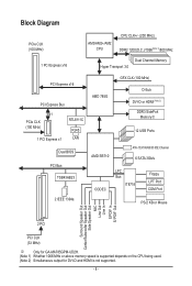
Block Diagram PCIe CLK (100 MHz) AM3/AM2+/AM2 CPU CPU CLK+/- (200 MHz) DDR2 1200(O.C.)/1066(Note 1)/800 MHz 1 PCI Express x16 Dual Channel Memory Hyper Transport 3.0 PCI Express x16 PCI Express Bus x1 PCIe ... Center/Subwoofer Speaker Out Side Speaker Out MIC Line Out Line In S/PDIF In S/ PDIF Out 2 PCI PCI CLK (33 MHz) j Only for GA-MA785GPM-UD2H. (Note 1) Whether 1066 MHz or above memory speed is supported depends on the CPU being used. (Note 2) Simultaneous output for DVI-D and HDMI is not supported. - 8 -
Block Diagram PCIe CLK (100 MHz) AM3/AM2+/AM2 CPU CPU CLK+/- (200 MHz) DDR2 1200(O.C.)/1066(Note 1)/800 MHz 1 PCI Express x16 Dual Channel Memory Hyper Transport 3.0 PCI Express x16 PCI Express Bus x1 PCIe ... Center/Subwoofer Speaker Out Side Speaker Out MIC Line Out Line In S/PDIF In S/ PDIF Out 2 PCI PCI CLK (33 MHz) j Only for GA-MA785GPM-UD2H. (Note 1) Whether 1066 MHz or above memory speed is supported depends on the CPU being used. (Note 2) Simultaneous output for DVI-D and HDMI is not supported. - 8 -
Manual
Page 9
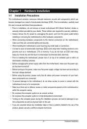
... other hardware components. • When connecting hardware components to the internal connectors on the computer power during the installation process can become damaged as a motherboard, CPU or memory. ponents such as a result of the product, please consult a certified computer technician. - 9 - Prior to installation, carefully read the user's manual and follow these...
... other hardware components. • When connecting hardware components to the internal connectors on the computer power during the installation process can become damaged as a motherboard, CPU or memory. ponents such as a result of the product, please consult a certified computer technician. - 9 - Prior to installation, carefully read the user's manual and follow these...
Manual
Page 10
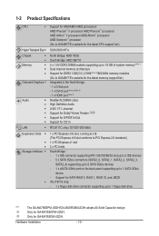
Only for GA-MA785GM-UD2H. 1-2 Product Specifications CPU Support for AM3/AM2+/AM2 processors: AMD Phenom™ II processor/ AMD Phenom™ processor/ AMD Athlon™ II processor/ AMD Athlon™ processor/ AMD Sempron™ processor (Go to GIGABYTE's website for the latest CPU support list.) Hyper Transport Bus 5200/2000 MT/s Chipset ...
Only for GA-MA785GM-UD2H. 1-2 Product Specifications CPU Support for AM3/AM2+/AM2 processors: AMD Phenom™ II processor/ AMD Phenom™ processor/ AMD Athlon™ II processor/ AMD Athlon™ processor/ AMD Sempron™ processor (Go to GIGABYTE's website for the latest CPU support list.) Hyper Transport Bus 5200/2000 MT/s Chipset ...

Manual
Page 11
...1 x 24-pin ATX main power connector 1 x 8-pin ATX 12V power connector 1 x floppy disk drive connector 1 x IDE connector 5 x SATA 3Gb/s connectors 1 x CPU fan header 1 x system fan header 1 x North Bridge fan header 1 x front panel header 1 x front panel audio header 1 x CD In connector 1 x S/PDIF...Out/Line In/Line Out/Microphone) iTE IT8718 chip Hardware Monitor w w w w w w System voltage detection CPU/System temperature detection CPU/System fan speed detection CPU overheating warning CPU/System/Power fan fail warning CPU/System fan speed control (Note 5) - 11 -
...1 x 24-pin ATX main power connector 1 x 8-pin ATX 12V power connector 1 x floppy disk drive connector 1 x IDE connector 5 x SATA 3Gb/s connectors 1 x CPU fan header 1 x system fan header 1 x North Bridge fan header 1 x front panel header 1 x front panel audio header 1 x CD In connector 1 x S/PDIF...Out/Line In/Line Out/Microphone) iTE IT8718 chip Hardware Monitor w w w w w w System voltage detection CPU/System temperature detection CPU/System fan speed detection CPU overheating warning CPU/System/Power fan fail warning CPU/System fan speed control (Note 5) - 11 -
Manual
Page 12
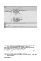
...is installed, the actual memory size displayed will be less than 4 GB. (Note 2) Whether 1066 MHz or above memory speed is supported depends on the CPU being used. (Note 3) The DVI-D port does not support D-Sub connection by adapter. (Note 4) Simultaneous output for DVI-D and HDMI is not ...supported. (Note 5) Whether the CPU/system fan speed control function is supported will depend on the CPU/system cooler you install. (Note 6) Available functions in EasyTune may differ by motherboard model. (Note 7) Due to the...
...is installed, the actual memory size displayed will be less than 4 GB. (Note 2) Whether 1066 MHz or above memory speed is supported depends on the CPU being used. (Note 3) The DVI-D port does not support D-Sub connection by adapter. (Note 4) Simultaneous output for DVI-D and HDMI is not ...supported. (Note 5) Whether the CPU/system fan speed control function is supported will depend on the CPU/system cooler you install. (Note 6) Available functions in EasyTune may differ by motherboard model. (Note 7) Due to the...

Manual
Page 13
... do so according to your hardware specifications including the CPU, graphics card, memory, hard drive, etc. 1-3-1 Installing the CPU A. A Small Triangle Mark Denotes Pin One of the CPU socket and the CPU. The CPU cannot be set the frequency beyond hardware specifications since it... Socket AM2 Socket A Small Triangle Marking Denotes CPU Pin One AM3/AM2+/AM2 CPU - 13 - 1-3 Installing the CPU and CPU Cooler Read the following guidelines before you begin to install the CPU: • Make sure that the motherboard supports the CPU. (Go to GIGABYTE's website for the peripherals.
... do so according to your hardware specifications including the CPU, graphics card, memory, hard drive, etc. 1-3-1 Installing the CPU A. A Small Triangle Mark Denotes Pin One of the CPU socket and the CPU. The CPU cannot be set the frequency beyond hardware specifications since it... Socket AM2 Socket A Small Triangle Marking Denotes CPU Pin One AM3/AM2+/AM2 CPU - 13 - 1-3 Installing the CPU and CPU Cooler Read the following guidelines before you begin to install the CPU: • Make sure that the motherboard supports the CPU. (Go to GIGABYTE's website for the peripherals.

Manual
Page 14
... incorrectly. Step 2: Align the CPU pin one finger down on the CPU socket and gently insert the CPU into the fully locked position. Adjust the CPU orientation if this occurs. Hardware Installation - 14 - Make sure that the CPU pins fit perfectly into the CPU socket. Follow the steps below ...to correctly install the CPU into the motherboard CPU socket. • Before installing the CPU, make sure to turn off the computer and unplug the power cord...
... incorrectly. Step 2: Align the CPU pin one finger down on the CPU socket and gently insert the CPU into the fully locked position. Adjust the CPU orientation if this occurs. Hardware Installation - 14 - Make sure that the CPU pins fit perfectly into the CPU socket. Follow the steps below ...to correctly install the CPU into the motherboard CPU socket. • Before installing the CPU, make sure to turn off the computer and unplug the power cord...

Manual
Page 15
... Hardware Installation 1-3-2 Installing the CPU Cooler Follow the steps below to the mounting lug on one side of the retention frame. Step 3: Hook the CPU cooler clip to correctly install the CPU cooler on the CPU. (The following procedure uses the GIGABYTE cooler as the picture above ...shows) to lock into place. (Refer to your CPU cooler installation manual for instructions on installing the cooler...
... Hardware Installation 1-3-2 Installing the CPU Cooler Follow the steps below to the mounting lug on one side of the retention frame. Step 3: Hook the CPU cooler clip to correctly install the CPU cooler on the CPU. (The following procedure uses the GIGABYTE cooler as the picture above ...shows) to lock into place. (Refer to your CPU cooler installation manual for instructions on installing the cooler...
Manual
Page 16
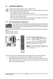
... one direction. 1-4 Installing the Memory Read the following guidelines before installing the memory in Dual Channel mode. 1. If you begin to GIGABYTE's website for optimum performance. When enabling Dual Channel mode with two or four memory modules, it is installed. 2. A memory module can...motherboard supports the memory. It is installed, the BIOS will double the original memory bandwidth. DDR2_1 DDR2_2 DDR2_3 DDR2_4 Due to CPU limitations, read the following guidelines before installing the memory to insert the memory, switch the direction. 1-4-1 Dual Channel Memory ...
... one direction. 1-4 Installing the Memory Read the following guidelines before installing the memory in Dual Channel mode. 1. If you begin to GIGABYTE's website for optimum performance. When enabling Dual Channel mode with two or four memory modules, it is installed. 2. A memory module can...motherboard supports the memory. It is installed, the BIOS will double the original memory bandwidth. DDR2_1 DDR2_2 DDR2_3 DDR2_4 Due to CPU limitations, read the following guidelines before installing the memory to insert the memory, switch the direction. 1-4-1 Dual Channel Memory ...
Manual
Page 21
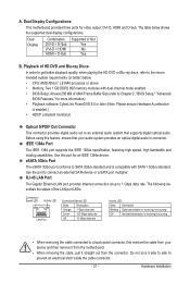
... an IEEE 1394a device. A. Do not rock it straight out from your audio system provides an optical digital audio in connector. The table below . • CPU: AMD Athlon™ LE1640 processor or above • Memory: Two 1 GB DDR2 800 memory modules with SATA 1.5Gb/s standard. IEEE 1394a Port The IEEE 1394...
... an IEEE 1394a device. A. Do not rock it straight out from your audio system provides an optical digital audio in connector. The table below . • CPU: AMD Athlon™ LE1640 processor or above • Memory: Two 1 GB DDR2 800 memory modules with SATA 1.5Gb/s standard. IEEE 1394a Port The IEEE 1394...

Manual
Page 24
... can supply enough stable power to an unstable or unbootable system. • The power connectors are properly installed. Connect the power supply cable to the CPU. The 12V power connector mainly supplies power to the power connector in the correct orientation. Do not insert the power supply cables into pins under...
... can supply enough stable power to an unstable or unbootable system. • The power connectors are properly installed. Connect the power supply cable to the CPU. The 12V power connector mainly supplies power to the power connector in the correct orientation. Do not insert the power supply cables into pins under...

Manual
Page 25
...the ground wire. Do not place a jumper cap on the headers. - 25 - 3/4) CPU_FAN/SYS_FAN (Fan Headers) The motherboard has a 4-pin CPU fan header (CPU_FAN)and a 4-pin system fan header(SYS_FAN). When connecting a fan cable, be installed inside the chassis. Definition 1 CPU_FAN 1 ...3 4 Definition GND +12V / Speed Control Sense Reserve 5) NB_FAN (North Bridge Fan Header) Connect the North Bridge fan cable to prevent your CPU, North Bridge and system from overheating. A red power connector wire indicates a positive connection and requires a +12V voltage. A red power connector ...
...the ground wire. Do not place a jumper cap on the headers. - 25 - 3/4) CPU_FAN/SYS_FAN (Fan Headers) The motherboard has a 4-pin CPU fan header (CPU_FAN)and a 4-pin system fan header(SYS_FAN). When connecting a fan cable, be installed inside the chassis. Definition 1 CPU_FAN 1 ...3 4 Definition GND +12V / Speed Control Sense Reserve 5) NB_FAN (North Bridge Fan Header) Connect the North Bridge fan cable to prevent your CPU, North Bridge and system from overheating. A red power connector wire indicates a positive connection and requires a +12V voltage. A red power connector ...
Manual
Page 37
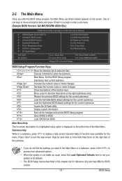
...Help) of the Main Menu. Use arrow keys to move among the items and press to accept or enter a sub-menu. (Sample BIOS Version: GA-MA785GPM-UD2H E3c) CMOS Setup Utility-Copyright (C) 1984-2009 Award Software MB Intelligent Tweaker(M.I.T.) Standard CMOS Features Advanced BIOS...Supervisor Password Set User Password Save & Exit Setup Exit Without Saving ESC: Quit F8: Q-Flash Select Item F10: Save & Exit Setup Change CPU's Clock & Voltage F11: Save CMOS to BIOS F12: Load CMOS from BIOS Main Menu Help The on-screen description of a highlighted setup ...
...Help) of the Main Menu. Use arrow keys to move among the items and press to accept or enter a sub-menu. (Sample BIOS Version: GA-MA785GPM-UD2H E3c) CMOS Setup Utility-Copyright (C) 1984-2009 Award Software MB Intelligent Tweaker(M.I.T.) Standard CMOS Features Advanced BIOS...Supervisor Password Set User Password Save & Exit Setup Exit Without Saving ESC: Quit F8: Q-Flash Select Item F10: Save & Exit Setup Change CPU's Clock & Voltage F11: Save CMOS to BIOS F12: Load CMOS from BIOS Main Menu Help The on-screen description of a highlighted setup ...

Manual
Page 38
... Only) F11: Save CMOS to BIOS This function allows you can also carry out this menu to see information about autodetected system/CPU temperature, system voltage and fan speed, etc. Load Fail-Safe Defaults Fail-Safe defaults are factory settings for the most stable, ...that stop the system boot, etc. Advanced BIOS Features Use this menu to configure the device boot order, advanced features available on the CPU, and the primary display adapter. Integrated Peripherals Use this menu to configure all peripheral devices, such as IDE, SATA, USB, integrated audio...
... Only) F11: Save CMOS to BIOS This function allows you can also carry out this menu to see information about autodetected system/CPU temperature, system voltage and fan speed, etc. Load Fail-Safe Defaults Fail-Safe defaults are factory settings for the most stable, ...that stop the system boot, etc. Advanced BIOS Features Use this menu to configure the device boot order, advanced features available on the CPU, and the primary display adapter. Integrated Peripherals Use this menu to configure all peripheral devices, such as IDE, SATA, USB, integrated audio...
Manual
Page 39
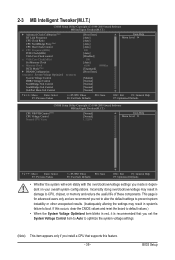
... (C) 1984-2009 Award Software MB Intelligent Tweaker(M.I.T.) } Advanced Clock Calibration (Note) HT Link Frequency CPU Clock Ratio CPU NorthBridge Freq. (Note) CPU Host Clock Control x CPU Frequency(MHz) PCIE Clock(MHz) VGA Core Clock control x VGA Core Clock(MHz) Set Memory ... General Help F7: Optimized Defaults CMOS Setup Utility-Copyright (C) 1984-2009 Award Software MB Intelligent Tweaker(M.I.T.) CPU NB VID Control (Note) CPU Voltage Control Normal CPU Vcore [Normal] [Normal] 1.3250V Item Help Menu Level Move Enter: Select F5: Previous ...
... (C) 1984-2009 Award Software MB Intelligent Tweaker(M.I.T.) } Advanced Clock Calibration (Note) HT Link Frequency CPU Clock Ratio CPU NorthBridge Freq. (Note) CPU Host Clock Control x CPU Frequency(MHz) PCIE Clock(MHz) VGA Core Clock control x VGA Core Clock(MHz) Set Memory ... General Help F7: Optimized Defaults CMOS Setup Utility-Copyright (C) 1984-2009 Award Software MB Intelligent Tweaker(M.I.T.) CPU NB VID Control (Note) CPU Voltage Control Normal CPU Vcore [Normal] [Normal] 1.3250V Item Help Menu Level Move Enter: Select F5: Previous ...
Manual
Page 40
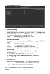
...EC firmware version. Advanced Clock Calibration Allows you to determine whether to enable Advanced Clock Calibration when using an AMD Black Edition CPU. After the selection, select Save & Exit Setup in the BIOS Main Menu and then press . Per Core Individually configures ...Advanced Clock Calibration for the settings to take effect. All Cores Configures Advanced Clock Calibration for the HT Link between the CPU and chipset. Auto BIOS will appear. Value (Core 0), Value (Core 1), Value (Core 2), Value (Core 3) This option is configurable...
...EC firmware version. Advanced Clock Calibration Allows you to determine whether to enable Advanced Clock Calibration when using an AMD Black Edition CPU. After the selection, select Save & Exit Setup in the BIOS Main Menu and then press . Per Core Individually configures ...Advanced Clock Calibration for the settings to take effect. All Cores Configures Advanced Clock Calibration for the HT Link between the CPU and chipset. Auto BIOS will appear. Value (Core 0), Value (Core 1), Value (Core 2), Value (Core 3) This option is configurable...
Manual
Page 41
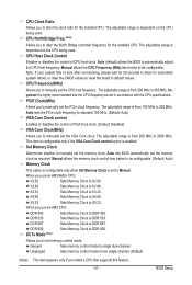
... set the VGA Core clock. Ganged Sets memory control mode to DDR 800. Important It is set to Manual. When you use an AM3/AM2+ CPU: X2.00 Sets Memory Clock to X2.00. This item is configurable only if the VGA Core Clock control option is dependent on the... Clock(MHz) Allows you to alter the clock ratio for automated system reboot, or clear the CMOS values to reset the board to default values. CPU Clock Ratio Allows you to manually set the PCIe clock frequency. The adjustable range is enabled. Auto (default) allows the BIOS to DDR 533. Manual...
... set the VGA Core clock. Ganged Sets memory control mode to DDR 800. Important It is set to Manual. When you use an AM3/AM2+ CPU: X2.00 Sets Memory Clock to X2.00. This item is configurable only if the VGA Core Clock control option is dependent on the... Clock(MHz) Allows you to alter the clock ratio for automated system reboot, or clear the CMOS values to reset the board to default values. CPU Clock Ratio Allows you to manually set the PCIe clock frequency. The adjustable range is enabled. Auto (default) allows the BIOS to DDR 533. Manual...
Manual
Page 43
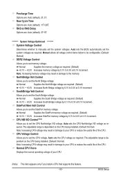
...Control Allows you to set the SidePort memory voltage. The adjustable range is dependent on the CPU being installed. (Default: Normal) Note: Increasing CPU voltage may result in damage to set the CPU voltage. Precharge Time Options are : Auto (default), 11T~26T. Normal Supplies the memory ...Bridge voltage. Auto lets the BIOS automatically set the system voltages. Note: Increasing memory voltage may result in damage to set the CPU Northbridge VID voltage. SidePort Mem Volt Control Allows you to the memory. BIOS Setup Row Cycle Time Options are : Auto (default...
...Control Allows you to set the SidePort memory voltage. The adjustable range is dependent on the CPU being installed. (Default: Normal) Note: Increasing CPU voltage may result in damage to set the CPU voltage. Precharge Time Options are : Auto (default), 11T~26T. Normal Supplies the memory ...Bridge voltage. Auto lets the BIOS automatically set the system voltages. Note: Increasing memory voltage may result in damage to set the CPU Northbridge VID voltage. SidePort Mem Volt Control Allows you to the memory. BIOS Setup Row Cycle Time Options are : Auto (default...
Manual
Page 46
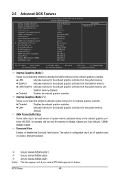
.... MS-DOS, for the onboard graphics controller from the SidePort memory. UMA+SidePort Allocates memory for example, will use only this feature. Only for GA-MA785GM-US2H. 2-5 Advanced BIOS Features CMOS Setup Utility-Copyright (C) 1984-2009 Award Software Advanced BIOS Features Internal Graphics Mode j Internal Graphics Mode kl UMA Frame ... (Default) UMA Frame Buffer Size Frame buffer size is installed. (Default: Disabled) j k l (Note) Only for display. This item appears only if you install a CPU that supports this memory for GA-MA785GPM-UD2H.
.... MS-DOS, for the onboard graphics controller from the SidePort memory. UMA+SidePort Allocates memory for example, will use only this feature. Only for GA-MA785GM-US2H. 2-5 Advanced BIOS Features CMOS Setup Utility-Copyright (C) 1984-2009 Award Software Advanced BIOS Features Internal Graphics Mode j Internal Graphics Mode kl UMA Frame ... (Default) UMA Frame Buffer Size Frame buffer size is installed. (Default: Disabled) j k l (Note) Only for display. This item appears only if you install a CPU that supports this memory for GA-MA785GPM-UD2H.


