Manual
Page 1
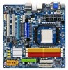
GA-MA785GPM-UD2H/ GA-MA785GM-UD2H/ GA-MA785GM-US2H AM2+/AM2 socket motherboard for AMD Phenom™ II processor/ AMD Phenom™ processor/ AMD Athlon™ II processor/ AMD Athlon™ processor/ AMD Sempron™ processor User's Manual Rev. 1001 12ME-MA785M2-1001R
GA-MA785GPM-UD2H/ GA-MA785GM-UD2H/ GA-MA785GM-US2H AM2+/AM2 socket motherboard for AMD Phenom™ II processor/ AMD Phenom™ processor/ AMD Athlon™ II processor/ AMD Athlon™ processor/ AMD Sempron™ processor User's Manual Rev. 1001 12ME-MA785M2-1001R
Manual
Page 3
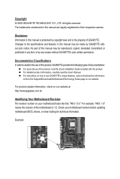
...169; 2009 GIGA-BYTE TECHNOLOGY CO., LTD. No part of this manual may be made by GIGABYTE without GIGABYTE's prior written permission. Disclaimer Information in this manual are legally registered to the specifications and features in this manual may be reproduced, copied, translated, transmitted, or published in any...with the product. Check your motherboard looks like this product, GIGABYTE provides the following types of documentations: For quick set-up of GIGABYTE. For instructions on how to assist in this manual is protected by any form or by copyright laws and is...
...169; 2009 GIGA-BYTE TECHNOLOGY CO., LTD. No part of this manual may be made by GIGABYTE without GIGABYTE's prior written permission. Disclaimer Information in this manual are legally registered to the specifications and features in this manual may be reproduced, copied, translated, transmitted, or published in any...with the product. Check your motherboard looks like this product, GIGABYTE provides the following types of documentations: For quick set-up of GIGABYTE. For instructions on how to assist in this manual is protected by any form or by copyright laws and is...
Manual
Page 5
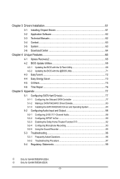
Chapter 3 Drivers Installation 61 3-1 Installing Chipset Drivers 61 3-2 Application Software 62 3-3 Technical Manuals 62 3-4 Contact...63 3-5 System...63 3-6 Download Center 64 Chapter 4 Unique Features 65 4-1 Xpress Recovery2 65 4-2 BIOS Update Utilities 68 4-2-1 Updating the BIOS with the Q-Flash ... Functionjk 92 5-2-4 Configuring Microphone Recording 93 5-2-5 Using the Sound Recorder 95 5-3 Troubleshooting 96 5-3-1 Frequently Asked Questions 96 5-3-2 Troubleshooting Procedure 97 5-4 Regulatory Statements 99 j Only for GA-MA785GM-UD2H. - 5 - k Only for GA-MA785GPM-UD2H.
Chapter 3 Drivers Installation 61 3-1 Installing Chipset Drivers 61 3-2 Application Software 62 3-3 Technical Manuals 62 3-4 Contact...63 3-5 System...63 3-6 Download Center 64 Chapter 4 Unique Features 65 4-1 Xpress Recovery2 65 4-2 BIOS Update Utilities 68 4-2-1 Updating the BIOS with the Q-Flash ... Functionjk 92 5-2-4 Configuring Microphone Recording 93 5-2-5 Using the Sound Recorder 95 5-3 Troubleshooting 96 5-3-1 Frequently Asked Questions 96 5-3-2 Troubleshooting Procedure 97 5-4 Regulatory Statements 99 j Only for GA-MA785GM-UD2H. - 5 - k Only for GA-MA785GPM-UD2H.
Manual
Page 6
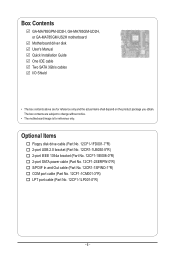
... (Part No. 12CR1-1SPINO-1*R) COM port cable (Part No. 12CF1-1CM001-3*R) LPT port cable (Part No. 12CF1-1LP001-0*R) - 6 - Box Contents GA-MA785GPM-UD2H, GA-MA785GM-UD2H, or GA-MA785GM-US2H motherboard Motherboard driver disk User's Manual Quick Installation Guide One IDE cable Two SATA 3Gb/s cables I/O Shield • The box contents above are subject to change without...
... (Part No. 12CR1-1SPINO-1*R) COM port cable (Part No. 12CF1-1CM001-3*R) LPT port cable (Part No. 12CF1-1LP001-0*R) - 6 - Box Contents GA-MA785GPM-UD2H, GA-MA785GM-UD2H, or GA-MA785GM-US2H motherboard Motherboard driver disk User's Manual Quick Installation Guide One IDE cable Two SATA 3Gb/s cables I/O Shield • The box contents above are subject to change without...
Manual
Page 9
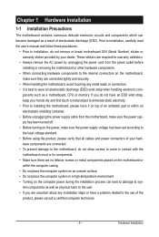
Prior to installation, carefully read the user's manual and follow these procedures: • Prior to installation, do not remove or break motherboard S/N (Serial Number) sticker or warranty sticker provided by unplugging the power ...
Prior to installation, carefully read the user's manual and follow these procedures: • Prior to installation, do not remove or break motherboard S/N (Serial Number) sticker or warranty sticker provided by unplugging the power ...

Manual
Page 15
... the steps below to correctly install the CPU cooler on the CPU. (The following procedure uses the GIGABYTE cooler as the picture above shows) to lock into place. (Refer to your CPU cooler installation manual for instructions on installing the cooler.) Step 5: Finally, attach the power connector of the CPU cooler to...
... the steps below to correctly install the CPU cooler on the CPU. (The following procedure uses the GIGABYTE cooler as the picture above shows) to lock into place. (Refer to your CPU cooler installation manual for instructions on installing the cooler.) Step 5: Finally, attach the power connector of the CPU cooler to...
Manual
Page 18
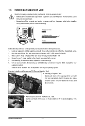
...: Gently push back on the lever on the top edge of the card until it is fully seated in your operating system. Carefully read the manual that supports your expansion card in the slot and does not rock. • Removing the Card from the chassis back panel. 2. After installing all expansion...
...: Gently push back on the lever on the top edge of the card until it is fully seated in your operating system. Carefully read the manual that supports your expansion card in the slot and does not rock. • Removing the Card from the chassis back panel. 2. After installing all expansion...
Manual
Page 33
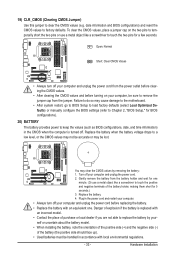
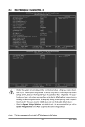
... do so may cause damage to the motherboard. • After system restart, go to BIOS Setup to load factory defaults (select Load Optimized Defaults) or manually configure the BIOS settings (refer to Chapter 2, "BIOS Setup," for BIOS configurations). 20) BATTERY The battery provides power to factory defaults. Gently remove the battery...
... do so may cause damage to the motherboard. • After system restart, go to BIOS Setup to load factory defaults (select Load Optimized Defaults) or manually configure the BIOS settings (refer to Chapter 2, "BIOS Setup," for BIOS configurations). 20) BATTERY The battery provides power to factory defaults. Gently remove the battery...
Manual
Page 39
... Control SouthBridge Volt Control SidePort Mem Volt Control [Press Enter] [Auto] [Auto] [Auto] [Auto] 200 [Auto] [Disabled] 500 [Auto] x4.00 800Mhz [Unganged] [Press Enter] [Manual] [Normal] [Normal] [Normal] [Normal] Item Help Menu Level Move Enter: Select F5: Previous Values +/-/PU/PD: Value F10: Save F6: Fail-Safe Defaults ESC...
... Control SouthBridge Volt Control SidePort Mem Volt Control [Press Enter] [Auto] [Auto] [Auto] [Auto] 200 [Auto] [Disabled] 500 [Auto] x4.00 800Mhz [Unganged] [Press Enter] [Manual] [Normal] [Normal] [Normal] [Normal] Item Help Menu Level Move Enter: Select F5: Previous Values +/-/PU/PD: Value F10: Save F6: Fail-Safe Defaults ESC...
Manual
Page 40
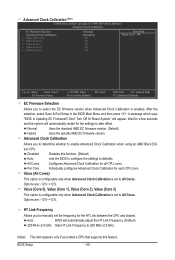
... adjust the HT Link Frequency. (Default) 200 MHz~2.0 GHz Sets HT Link Frequency to 200 MHz~2.0 GHz. (Note) This item appears only if you to manually set the frequency for each CPU core. Wait for a few seconds and the system will automatically restart for all CPU cores. Options are : -12%~+12%.
... adjust the HT Link Frequency. (Default) 200 MHz~2.0 GHz Sets HT Link Frequency to 200 MHz~2.0 GHz. (Note) This item appears only if you to manually set the frequency for each CPU core. Wait for a few seconds and the system will automatically restart for all CPU cores. Options are : -12%~+12%.
Manual
Page 41
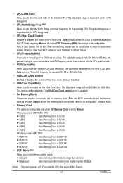
... the board to 200 MHz. The adjustable range is from 200 MHz to X5.33. The adjustable range is from 200 MHz to X2.66. Manual allows the memory clock control item below to be configurable. (Default: Auto) Memory Clock This option is configurable only when Set Memory Clock is from... Sets Memory Clock to DDR 533. DDR 533 Sets Memory Clock to X3.33. The adjustable range is enabled. Auto (default) allows the BIOS to manually set memory control mode. Auto sets the PCIe clock frequency to standard 100 MHz. (Default: Auto) VGA Core Clock control Enables or disables the control...
... the board to 200 MHz. The adjustable range is from 200 MHz to X5.33. The adjustable range is from 200 MHz to X2.66. Manual allows the memory clock control item below to be configurable. (Default: Auto) Memory Clock This option is configurable only when Set Memory Clock is from... Sets Memory Clock to DDR 533. DDR 533 Sets Memory Clock to X3.33. The adjustable range is enabled. Auto (default) allows the BIOS to manually set memory control mode. Auto sets the PCIe clock frequency to standard 100 MHz. (Default: Auto) VGA Core Clock control Enables or disables the control...

Manual
Page 42
...), 75ns, 105ns, 127.5ns, 195ns, 327.5ns. Minimum RAS Active Time Options are: Auto (default), 5T~18T. 1T/2T Command Timing Options are : Auto (default), Manual. RAS to be configurable. Trfc0 for DIMM2 Options are: Auto (default), 75ns, 105ns, 127.5ns, 195ns, 327.5ns. Row Precharge Time Options are : Auto (default... Enter: Select F5: Previous Values +/-/PU/PD: Value F10: Save F6: Fail-Safe Defaults ESC: Exit F1: General Help F7: Optimized Defaults DDRII Timing Items Manual allows all DDR2 Timing items below to CAS R/W Delay Options are: Auto (default), 3T~6T.
...), 75ns, 105ns, 127.5ns, 195ns, 327.5ns. Minimum RAS Active Time Options are: Auto (default), 5T~18T. 1T/2T Command Timing Options are : Auto (default), Manual. RAS to be configurable. Trfc0 for DIMM2 Options are: Auto (default), 75ns, 105ns, 127.5ns, 195ns, 327.5ns. Row Precharge Time Options are : Auto (default... Enter: Select F5: Previous Values +/-/PU/PD: Value F10: Save F6: Fail-Safe Defaults ESC: Exit F1: General Help F7: Optimized Defaults DDRII Timing Items Manual allows all DDR2 Timing items below to CAS R/W Delay Options are: Auto (default), 3T~6T.
Manual
Page 43
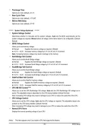
...Auto (default), 2T~5T. ******** System Voltage Optimized ******** System Voltage Control Determines whether to set the CPU voltage. Manual allows all voltage control items below to be configurable. (Default: Manual) DDR2 Voltage Control Allows you install a CPU that supports this feature. - 43 - Note: Increasing memory voltage...0.3V at 0.1V increment. CPU Voltage Control Allows you to your CPU (Note) This item appears only if you to manually set the system voltages as required. BIOS Setup NorthBridge Volt Control Allows you to set the SidePort memory voltage. SidePort Mem Volt...
...Auto (default), 2T~5T. ******** System Voltage Optimized ******** System Voltage Control Determines whether to set the CPU voltage. Manual allows all voltage control items below to be configurable. (Default: Manual) DDR2 Voltage Control Allows you install a CPU that supports this feature. - 43 - Note: Increasing memory voltage...0.3V at 0.1V increment. CPU Voltage Control Allows you to your CPU (Note) This item appears only if you to manually set the system voltages as required. BIOS Setup NorthBridge Volt Control Allows you to set the SidePort memory voltage. SidePort Mem Volt...

Manual
Page 45
.... - 45 - Halt On Allows you to the information on the hard drive. The following fields display your system. If you wish to enter the parameters manually, refer to specify whether the installed floppy disk drive is 3-mode floppy disk drive, a Japanese standard floppy disk drive. BIOS Setup
.... - 45 - Halt On Allows you to the information on the hard drive. The following fields display your system. If you wish to enter the parameters manually, refer to specify whether the installed floppy disk drive is 3-mode floppy disk drive, a Japanese standard floppy disk drive. BIOS Setup
Manual
Page 61
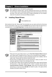
... installing the operating system, insert the motherboard driver disk into your system and then list all the recommended drivers. Or click Install Single Items to manually select the drivers you wish to install. Failure to do so may affect the driver installation. • Some device drivers will continue to install other...
... installing the operating system, insert the motherboard driver disk into your system and then list all the recommended drivers. Or click Install Single Items to manually select the drivers you wish to install. Failure to do so may affect the driver installation. • Some device drivers will continue to install other...
Manual
Page 62
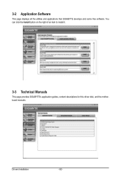
3-2 Application Software This page displays all the utilities and applications that GIGABYTE develops and some free software. Drivers Installation - 62 - You can click the Install button on the right of an item to install it. 3-3 Technical Manuals This page provides GIGABYTE's application guides, content descriptions for this driver disk, and the motherboard manuals.
3-2 Application Software This page displays all the utilities and applications that GIGABYTE develops and some free software. Drivers Installation - 62 - You can click the Install button on the right of an item to install it. 3-3 Technical Manuals This page provides GIGABYTE's application guides, content descriptions for this driver disk, and the motherboard manuals.

Manual
Page 68
...Flash tool frees you can access Q-Flash by adding one more physical BIOS chip. site and update the BIOS. GA-MA785GPM-UD2H E3c . . . . : BIOS Setup : XpressRecovery2 : Boot Menu : Qflash 06/05/2009-...enhances protection for the safety and stability of system safety, users cannot update the backup BIOS manually. Normally, the system works on the next system boot and copy the BIOS file to...like MS-DOS or Window first. Extract the file and save the new BIOS file (e.g. From GIGABYTE's website, download the latest compressed BIOS update file that support DualBIOS have two BIOS onboard, a...
...Flash tool frees you can access Q-Flash by adding one more physical BIOS chip. site and update the BIOS. GA-MA785GPM-UD2H E3c . . . . : BIOS Setup : XpressRecovery2 : Boot Menu : Qflash 06/05/2009-...enhances protection for the safety and stability of system safety, users cannot update the backup BIOS manually. Normally, the system works on the next system boot and copy the BIOS file to...like MS-DOS or Window first. Extract the file and save the new BIOS file (e.g. From GIGABYTE's website, download the latest compressed BIOS update file that support DualBIOS have two BIOS onboard, a...
Manual
Page 71
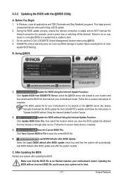
...Follow the on -screen instructions to complete. 3. Make sure that is not present on the @BIOS server site, please manually download the BIOS update file from GIGABYTE's website and follow the instructions in a corrupted BIOS or a system that the BIOS file to be flashed matches your ... after the system restarts. Updating the BIOS with the @BIOS Utility A. Follow the on -screen instructions to complete. Do not use the G.O.M. (GIGABYTE Online Management) function when using @BIOS. 4. B. If the BIOS update file for example, avoid a power loss or switching off the Internet). ...
...Follow the on -screen instructions to complete. 3. Make sure that is not present on the @BIOS server site, please manually download the BIOS update file from GIGABYTE's website and follow the instructions in a corrupted BIOS or a system that the BIOS file to be flashed matches your ... after the system restarts. Updating the BIOS with the @BIOS Utility A. Follow the on -screen instructions to complete. Do not use the G.O.M. (GIGABYTE Online Management) function when using @BIOS. 4. B. If the BIOS update file for example, avoid a power loss or switching off the Internet). ...
Manual
Page 80
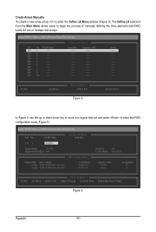
... LD 9 ---- LD 10 ---- LD No RAID Mode [ Define LD Menu ] Total Drv LD 1 RAID 0 0 Stripe Block: 64 KB Gigabyte Boundary: ON [ Drives Assignments ] Channel:ID Drive Model 1:Mas WDC WD800JD-22LSA0 2:Mas WDC WD800JD-22LSA0 Capabilities SATA 3G SATA 3G Fast Init:... (c) 2008 Advanced Micro Devices, Inc. [ Define LD Menu ] LD No RAID Mode LD 1 ---- LD 3 ---- Create Arrays Manually To create a new array, press to enter the RAID configuration menu (Figure 5). The Define LD selection from the Main Menu allows ...
... LD 9 ---- LD 10 ---- LD No RAID Mode [ Define LD Menu ] Total Drv LD 1 RAID 0 0 Stripe Block: 64 KB Gigabyte Boundary: ON [ Drives Assignments ] Channel:ID Drive Model 1:Mas WDC WD800JD-22LSA0 2:Mas WDC WD800JD-22LSA0 Capabilities SATA 3G SATA 3G Fast Init:... (c) 2008 Advanced Micro Devices, Inc. [ Define LD Menu ] LD No RAID Mode LD 1 ---- LD 3 ---- Create Arrays Manually To create a new array, press to enter the RAID configuration menu (Figure 5). The Define LD selection from the Main Menu allows ...
Manual
Page 88
... retask the Center/Subwoofer speaker out jack to be Side speaker out. • To install a microphone, connect your microphone to the Mic in jack and manually configure the jack for microphone functionality. • Audio signals will appear in the notification area. Appendix - 88 - woofer speaker out jack, you want to mute...
... retask the Center/Subwoofer speaker out jack to be Side speaker out. • To install a microphone, connect your microphone to the Mic in jack and manually configure the jack for microphone functionality. • Audio signals will appear in the notification area. Appendix - 88 - woofer speaker out jack, you want to mute...


