Manual
Page 4
Table of Contents Box Contents ...6 OptionalItems ...6 GA-MA770T-UD3/US3 Motherboard Layout 7 Block Diagram ...8 Chapter 1 Hardware Installation 9 1-1 Installation Precautions 9 1-2 Product Specifications 10 1-3 Installing the CPU and CPU Cooler 13 1-3-1 ... Startup Screen 34 2-2 The Main Menu 35 2-3 MB Intelligent Tweaker(M.I.T 37 2-4 Standard CMOS Features 42 2-5 Advanced BIOS Features 44 2-6 IntegratedPeripherals 46 2-7 Power Management Setup 50 2-8 PC Health Status 52 2-9 Load Fail-Safe Defaults 54 2-10 Load Optimized Defaults 54 2-11 Set Supervisor/User Password 55 2-12 Save...
Table of Contents Box Contents ...6 OptionalItems ...6 GA-MA770T-UD3/US3 Motherboard Layout 7 Block Diagram ...8 Chapter 1 Hardware Installation 9 1-1 Installation Precautions 9 1-2 Product Specifications 10 1-3 Installing the CPU and CPU Cooler 13 1-3-1 ... Startup Screen 34 2-2 The Main Menu 35 2-3 MB Intelligent Tweaker(M.I.T 37 2-4 Standard CMOS Features 42 2-5 Advanced BIOS Features 44 2-6 IntegratedPeripherals 46 2-7 Power Management Setup 50 2-8 PC Health Status 52 2-9 Load Fail-Safe Defaults 54 2-10 Load Optimized Defaults 54 2-11 Set Supervisor/User Password 55 2-12 Save...
Manual
Page 6
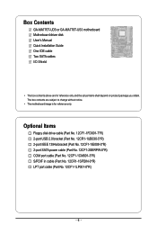
Box Contents GA-MA770T-UD3 or GA-MA770T-US3 motherboard Motherboard driver disk User's Manual Quick Installation Guide One IDE cable Two SATA cables I/O Shield • The box contents above are subject to ... Floppy disk drive cable (Part No. 12CF1-1FD001-7*R) 2-port USB 2.0 bracket (Part No. 12CR1-1UB030-5*R) 2-port IEEE 1394a bracket (Part No. 12CF1-1IE008-0*R) 2-port SATA power cable (Part No. 12CF1-2SERPW-0*R) COM port cable (Part No. 12CF1-1CM001-3*R) S/PDIF in cable (Part No. 12CR1-1SPDIN-0*R) LPT port cable (Part No. 12CF1...
Box Contents GA-MA770T-UD3 or GA-MA770T-US3 motherboard Motherboard driver disk User's Manual Quick Installation Guide One IDE cable Two SATA cables I/O Shield • The box contents above are subject to ... Floppy disk drive cable (Part No. 12CF1-1FD001-7*R) 2-port USB 2.0 bracket (Part No. 12CR1-1UB030-5*R) 2-port IEEE 1394a bracket (Part No. 12CF1-1IE008-0*R) 2-port SATA power cable (Part No. 12CF1-2SERPW-0*R) COM port cable (Part No. 12CF1-1CM001-3*R) S/PDIF in cable (Part No. 12CR1-1SPDIN-0*R) LPT port cable (Part No. 12CF1...

Manual
Page 9
... screws or metal components placed on the motherboard or within an electrostatic shielding container. • Before unplugging the power supply cable from the power outlet before installing or removing the motherboard or other hardware components. • When connecting hardware components to the internal...an uneven surface. • Do not place the computer system in a high-temperature environment. • Turning on the computer power during the installation process can become damaged as a motherboard, CPU or memory. These stickers are required for warranty validation. • Always...
... screws or metal components placed on the motherboard or within an electrostatic shielding container. • Before unplugging the power supply cable from the power outlet before installing or removing the motherboard or other hardware components. • When connecting hardware components to the internal...an uneven surface. • Do not place the computer system in a high-temperature environment. • Turning on the computer power during the installation process can become damaged as a motherboard, CPU or memory. These stickers are required for warranty validation. • Always...

Manual
Page 11
... Out header 2 x USB 2.0/1.1 headers 1 x IEEE 1394a header 1 x parallel port header 1 x serial port header 1 x power LED header 1 x chassis intrusion header Back Panel 1 x PS/2 keyboard port Connectors 1 x PS/2 mouse port 1 x coaxial S/PDIF Out... System voltage detection CPU/System temperature detection CPU/System/Power fan speed detection CPU overheating warning CPU/System/Power fan fail warning CPU/System fan speed control (Note 4) BIOS ...
... Out header 2 x USB 2.0/1.1 headers 1 x IEEE 1394a header 1 x parallel port header 1 x serial port header 1 x power LED header 1 x chassis intrusion header Back Panel 1 x PS/2 keyboard port Connectors 1 x PS/2 mouse port 1 x coaxial S/PDIF Out... System voltage detection CPU/System temperature detection CPU/System/Power fan speed detection CPU overheating warning CPU/System/Power fan fail warning CPU/System fan speed control (Note 4) BIOS ...

Manual
Page 13
... Triangle Mark Denotes Pin One of the CPU. • Do not turn off the computer and unplug the power cord from the power outlet before you wish to set beyond the standard specifications, please do so according to your hardware specifications including the... CPU, graphics card, memory, hard drive, etc. 1-3-1 Installing the CPU A. Locate the pin one of the CPU. Hardware Installation mended that the motherboard supports the CPU. (Go to GIGABYTE...
... Triangle Mark Denotes Pin One of the CPU. • Do not turn off the computer and unplug the power cord from the power outlet before you wish to set beyond the standard specifications, please do so according to your hardware specifications including the... CPU, graphics card, memory, hard drive, etc. 1-3-1 Installing the CPU A. Locate the pin one of the CPU. Hardware Installation mended that the motherboard supports the CPU. (Go to GIGABYTE...
Manual
Page 14
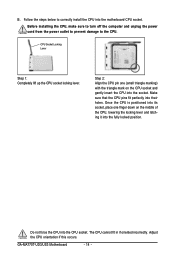
...Step 1: Completely lift up the CPU socket locking lever. Do not force the CPU into their holes. The CPU cannot fit in if oriented incorrectly. GA-MA770T-UD3/US3 Motherboard - 14 - Follow the steps below to the CPU. Once the CPU is positioned into its socket, place one (small triangle marking) with... gently insert the CPU into the motherboard CPU socket. Before installing the CPU, make sure to turn off the computer and unplug the power cord from the power outlet to prevent damage to correctly install the CPU into the socket. B. Adjust the CPU orientation if this occurs.
...Step 1: Completely lift up the CPU socket locking lever. Do not force the CPU into their holes. The CPU cannot fit in if oriented incorrectly. GA-MA770T-UD3/US3 Motherboard - 14 - Follow the steps below to the CPU. Once the CPU is positioned into its socket, place one (small triangle marking) with... gently insert the CPU into the motherboard CPU socket. Before installing the CPU, make sure to turn off the computer and unplug the power cord from the power outlet to prevent damage to correctly install the CPU into the socket. B. Adjust the CPU orientation if this occurs.

Manual
Page 15
...CPU. 1-3-2 Installing the CPU Cooler Follow the steps below to correctly install the CPU cooler on the CPU. (The following procedure uses the GIGABYTE cooler as the picture above shows) to lock into place. (Refer to your CPU cooler installation manual for instructions on installing the cooler.) ...Step 5: Finally, attach the power connector of the CPU cooler to the CPU fan header (CPU_FAN) on the motherboard. Hardware Installation Step 4: Turn the cam handle from the...
...CPU. 1-3-2 Installing the CPU Cooler Follow the steps below to correctly install the CPU cooler on the CPU. (The following procedure uses the GIGABYTE cooler as the picture above shows) to lock into place. (Refer to your CPU cooler installation manual for instructions on installing the cooler.) ...Step 5: Finally, attach the power connector of the CPU cooler to the CPU fan header (CPU_FAN) on the motherboard. Hardware Installation Step 4: Turn the cam handle from the...
Manual
Page 16
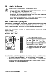
...can be installed in the DDR3_1 and DDR3_2 sockets. GA-MA770T-UD3/US3 Motherboard - 16 - If you are unable to install the memory: • Make sure that the motherboard supports the memory. Dual Channel mode cannot be used . (Go to GIGABYTE's website for optimum performance. It is installed. 2....the same colored DDR3 sockets for the latest memory support list.) • Always turn off the computer and unplug the power cord from the power outlet before you begin to insert the memory, switch the direction. 1-4-1 Dual Channel Memory Configuration This motherboard provides four ...
...can be installed in the DDR3_1 and DDR3_2 sockets. GA-MA770T-UD3/US3 Motherboard - 16 - If you are unable to install the memory: • Make sure that the motherboard supports the memory. Dual Channel mode cannot be used . (Go to GIGABYTE's website for optimum performance. It is installed. 2....the same colored DDR3 sockets for the latest memory support list.) • Always turn off the computer and unplug the power cord from the power outlet before you begin to insert the memory, switch the direction. 1-4-1 Dual Channel Memory Configuration This motherboard provides four ...

Manual
Page 17
.... Place the memory module on this motherboard. 1-4-2 Installing a Memory Before installing a memory module , make sure to turn off the computer and unplug the power cord from the power outlet to prevent damage to install DDR3 DIMMs on the socket. Step 2: The clips at both ends of the memory module. DDR3 and DDR2...
.... Place the memory module on this motherboard. 1-4-2 Installing a Memory Before installing a memory module , make sure to turn off the computer and unplug the power cord from the power outlet to prevent damage to install DDR3 DIMMs on the socket. Step 2: The clips at both ends of the memory module. DDR3 and DDR2...
Manual
Page 18
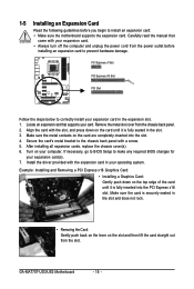
...back panel with your operating system. After installing all expansion cards, replace the chassis cover(s). 6. Remove the metal slot cover from the power outlet before you begin to install an expansion card: • Make sure the motherboard supports the expansion card. Install the driver provided ... necessary, go to BIOS Setup to make any required BIOS changes for your computer. Locate an expansion slot that came with a screw. 5. GA-MA770T-UD3/US3 Motherboard - 18 - PCI Express x1 Slot PCI Express x16 Slot PCI Slot Follow the steps below to correctly install your card. 1-5 ...
...back panel with your operating system. After installing all expansion cards, replace the chassis cover(s). 6. Remove the metal slot cover from the power outlet before you begin to install an expansion card: • Make sure the motherboard supports the expansion card. Install the driver provided ... necessary, go to BIOS Setup to make any required BIOS changes for your computer. Locate an expansion slot that came with a screw. 5. GA-MA770T-UD3/US3 Motherboard - 18 - PCI Express x1 Slot PCI Express x16 Slot PCI Slot Follow the steps below to correctly install your card. 1-5 ...

Manual
Page 21
.../F_USB2 17) F_1394 18) LPT 19) COMA 20) CI 21) CLR_CMOS Read the following guidelines before turning on the motherboard. - 21 - Unplug the power cord from the power outlet to prevent damage to the devices. • After installing the device and before connecting external devices: • First make sure the device cable...
.../F_USB2 17) F_1394 18) LPT 19) COMA 20) CI 21) CLR_CMOS Read the following guidelines before turning on the motherboard. - 21 - Unplug the power cord from the power outlet to prevent damage to the devices. • After installing the device and before connecting external devices: • First make sure the device cable...
Manual
Page 22
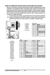
... for 2x12-pin ATX) GA-MA770T-UD3/US3 Motherboard - 22 - Before connecting the power connector, first make sure the power supply is not connected, the computer will not start. 1/2) ATX_12V_2X4/ATX (2x4 12V Power Connector and 2x12 Main Power Connector) With the use of the power connector, the power supply can supply enough stable power to all devices are properly...
... for 2x12-pin ATX) GA-MA770T-UD3/US3 Motherboard - 22 - Before connecting the power connector, first make sure the power supply is not connected, the computer will not start. 1/2) ATX_12V_2X4/ATX (2x4 12V Power Connector and 2x12 Main Power Connector) With the use of the power connector, the power supply can supply enough stable power to all devices are properly...

Manual
Page 23
... 2 - 23 - 3/4/5) CPU_FAN/SYS_FAN1/SYS_FAN2/PWR_FAN (Fan Headers) The motherboard has a 4-pin CPU fan header (CPU_FAN), a 3-pin (SYS_FAN2) and a 4-pin (SYS_FAN1) system fan headers, and a 3-pin power fan header (PWR_FAN). Overheating may hang. • These fan headers are : 360 KB, 720 KB, 1.2 MB, 1.44 MB, and 2.88 MB. The pin 1 of floppy...
... 2 - 23 - 3/4/5) CPU_FAN/SYS_FAN1/SYS_FAN2/PWR_FAN (Fan Headers) The motherboard has a 4-pin CPU fan header (CPU_FAN), a 3-pin (SYS_FAN2) and a 4-pin (SYS_FAN1) system fan headers, and a 3-pin power fan header (PWR_FAN). Overheating may hang. • These fan headers are : 360 KB, 720 KB, 1.2 MB, 1.44 MB, and 2.88 MB. The pin 1 of floppy...

Manual
Page 25
...Replace the battery when the battery voltage drops to replace the battery by removing the battery: 1. Plug in S3/S4 sleep state or powered off your computer and unplug the power cord. 2. Turn off . Danger of explosion if the battery is in accordance with local environmental regulations. - 25 - 9) PWR_LED ... CMOS when the computer is operating. System Status LED S0 On S1 Blinking S3/S4/S5 Off 10) BAT (BATTERY) The battery provides power to touch the positive and negative terminals of the battery (the positive side should face up). • Used batteries must be handled in ...
...Replace the battery when the battery voltage drops to replace the battery by removing the battery: 1. Plug in S3/S4 sleep state or powered off your computer and unplug the power cord. 2. Turn off . Danger of explosion if the battery is in accordance with local environmental regulations. - 25 - 9) PWR_LED ... CMOS when the computer is operating. System Status LED S0 On S1 Blinking S3/S4/S5 Off 10) BAT (BATTERY) The battery provides power to touch the positive and negative terminals of the battery (the positive side should face up). • Used batteries must be handled in ...
Manual
Page 26
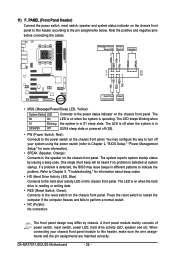
...the system is operating. Message/Power/ Power Sleep LED Switch Speaker MSG+ MSG- The LED keeps blinking when S1 Blinking the system is reading or writing data. • RES (Reset Switch, Green): Connects to the speaker on the chassis front panel. GA-MA770T-UD3/US3 Motherboard - 26 - 11...) F_PANEL (Front Panel Header) Connect the power switch, reset switch, speaker and system status indicator on the chassis front panel to this header, make...
...the system is operating. Message/Power/ Power Sleep LED Switch Speaker MSG+ MSG- The LED keeps blinking when S1 Blinking the system is reading or writing data. • RES (Reset Switch, Green): Connects to the speaker on the chassis front panel. GA-MA770T-UD3/US3 Motherboard - 26 - 11...) F_PANEL (Front Panel Header) Connect the power switch, reset switch, speaker and system status indicator on the chassis front panel to this header, make...

Manual
Page 27
... to the instructions on each wire instead of the motherboard header. Pin No. Hardware Installation Definition 1 MIC2_L Pin No. 1 Definition MIC 2 1 2 3 GND MIC2_R 2 GND 3 MIC Power 4 -ACZ_DET 4 NC 5 LINE2_R 5 Line Out (R) 6 GND 6 NC 7 FAUDIO_JD 7 NC 8 No Pin 8 No Pin 9 LINE2_L 9 Line Out (L) 10 GND 10 NC • The front panel audio...
... to the instructions on each wire instead of the motherboard header. Pin No. Hardware Installation Definition 1 MIC2_L Pin No. 1 Definition MIC 2 1 2 3 GND MIC2_R 2 GND 3 MIC Power 4 -ACZ_DET 4 NC 5 LINE2_R 5 Line Out (R) 6 GND 6 NC 7 FAUDIO_JD 7 NC 8 No Pin 8 No Pin 9 LINE2_L 9 Line Out (L) 10 GND 10 NC • The front panel audio...
Manual
Page 28
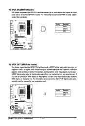
...card and have digital audio output from your motherboard to your motherboard to certain expansion cards like graphics cards and sound cards. Definition 1 Power 2 SPDIFI 1 3 GND 15) SPDIF_OUT (S/PDIF Out Header) This header supports digital S/PDIF Out and connects a S/PDIF digital audio.... For information about connecting the S/PDIF digital audio cable, carefully read the manual for your expansion card. Definition 1 SPDIFO 1 2 GND GA-MA770T-UD3/US3 Motherboard - 28 - 14) SPDIF_IN (S/PDIF In Header) This header supports digital S/PDIF In and can connect to use a S/PDIF...
...card and have digital audio output from your motherboard to your motherboard to certain expansion cards like graphics cards and sound cards. Definition 1 Power 2 SPDIFI 1 3 GND 15) SPDIF_OUT (S/PDIF Out Header) This header supports digital S/PDIF Out and connects a S/PDIF digital audio.... For information about connecting the S/PDIF digital audio cable, carefully read the manual for your expansion card. Definition 1 SPDIFO 1 2 GND GA-MA770T-UD3/US3 Motherboard - 28 - 14) SPDIF_IN (S/PDIF In Header) This header supports digital S/PDIF In and can connect to use a S/PDIF...
Manual
Page 29
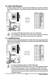
...bracket cable into the USB header. • Prior to installing the USB bracket, be sure to turn off your computer and unplug the power cord from the power outlet to prevent damage to the USB bracket. 17) F_1394 (IEEE 1394a Header) The header conforms to USB 2.0/1.1 specification. The IEEE ... an optional IEEE 1394a bracket. For purchasing the optional USB bracket, please contact the local dealer. 10 9 2 1 Pin No. 1 2 3 4 5 6 7 8 9 10 Definition Power (5V) Power (5V) USB DXUSB DYUSB DX+ USB DY+ GND GND No Pin NC • Do not plug the IEEE 1394 bracket (2x5-pin) cable into the...
...bracket cable into the USB header. • Prior to installing the USB bracket, be sure to turn off your computer and unplug the power cord from the power outlet to prevent damage to the USB bracket. 17) F_1394 (IEEE 1394a Header) The header conforms to USB 2.0/1.1 specification. The IEEE ... an optional IEEE 1394a bracket. For purchasing the optional USB bracket, please contact the local dealer. 10 9 2 1 Pin No. 1 2 3 4 5 6 7 8 9 10 Definition Power (5V) Power (5V) USB DXUSB DYUSB DX+ USB DY+ GND GND No Pin NC • Do not plug the IEEE 1394 bracket (2x5-pin) cable into the...

Manual
Page 31
... to touch the two pins for BIOS configurations). - 31 - To clear the CMOS values, place a jumper cap on your computer and unplug the power cord from the power outlet before clearing the CMOS values. • After clearing the CMOS values and before turning on the two pins to temporarily short the two...
... to touch the two pins for BIOS configurations). - 31 - To clear the CMOS values, place a jumper cap on your computer and unplug the power cord from the power outlet before clearing the CMOS values. • After clearing the CMOS values and before turning on the two pins to temporarily short the two...

Manual
Page 33
...flash the BIOS, do not encounter problems using the current version of BIOS, it with caution. BIOS Setup To upgrade the BIOS, use either the GIGABYTE Q-Flash or @BIOS utility. • Q-Flash allows the user to quickly and easily upgrade or back up BIOS without entering the operating system. ... in Chapter 1 for the beep codes description. • It is turned off, the battery on the motherboard. Its major functions include conducting the Power-On Self-Test (POST) during the POST. Chapter 2 BIOS Setup BIOS (Basic Input and Output System) records hardware parameters of the system in ...
...flash the BIOS, do not encounter problems using the current version of BIOS, it with caution. BIOS Setup To upgrade the BIOS, use either the GIGABYTE Q-Flash or @BIOS utility. • Q-Flash allows the user to quickly and easily upgrade or back up BIOS without entering the operating system. ... in Chapter 1 for the beep codes description. • It is turned off, the battery on the motherboard. Its major functions include conducting the Power-On Self-Test (POST) during the POST. Chapter 2 BIOS Setup BIOS (Basic Input and Output System) records hardware parameters of the system in ...


