Manual
Page 1
GA-MA770-UD3/ GA-MA770-US3 AM2+/AM2 socket motherboard for AMD PhenomTM FX processor/AMD PhenomTM X4 processor/ AMD PhenomTM X3 processor/AMD AthlonTM X2 processor/ AMD AthlonTM processor/AMD SempronTM X2 processor/ AMD SempronTM processor User's Manual Rev. 1001 12ME-MA77UDS3-1001R
GA-MA770-UD3/ GA-MA770-US3 AM2+/AM2 socket motherboard for AMD PhenomTM FX processor/AMD PhenomTM X4 processor/ AMD PhenomTM X3 processor/AMD AthlonTM X2 processor/ AMD AthlonTM processor/AMD SempronTM X2 processor/ AMD SempronTM processor User's Manual Rev. 1001 12ME-MA77UDS3-1001R
Manual
Page 3
... this manual may be reproduced, copied, translated, transmitted, or published in the use GIGABYTE's unique features, read the User's Manual. For instructions on your motherboard revision before updating motherboard BIOS, drivers, or when looking for technical information. For example, "REV: 1.0" ...For quick set-up of this manual is 1.0. For product-related information, check on our website at: http://www.gigabyte.com.tw Identifying Your Motherboard Revision The revision number on how to their respective owners. Example: Copyright © 2008 GIGA-BYTE TECHNOLOGY CO., ...
... this manual may be reproduced, copied, translated, transmitted, or published in the use GIGABYTE's unique features, read the User's Manual. For instructions on your motherboard revision before updating motherboard BIOS, drivers, or when looking for technical information. For example, "REV: 1.0" ...For quick set-up of this manual is 1.0. For product-related information, check on our website at: http://www.gigabyte.com.tw Identifying Your Motherboard Revision The revision number on how to their respective owners. Example: Copyright © 2008 GIGA-BYTE TECHNOLOGY CO., ...
Manual
Page 4
Table of Contents Box Contents ...6 Optional Items...6 GA-MA770-UD3/US3 Motherboard Layout 7 Block Diagram...8 Chapter 1 Hardware Installation 9 1-1 Installation Precautions 9 1-2 Product Specifications 10 1-3 Installing the CPU and CPU Cooler 13 1-3-1 Installing the CPU 13 1-3-2 Installing the CPU ...
Table of Contents Box Contents ...6 Optional Items...6 GA-MA770-UD3/US3 Motherboard Layout 7 Block Diagram...8 Chapter 1 Hardware Installation 9 1-1 Installation Precautions 9 1-2 Product Specifications 10 1-3 Installing the CPU and CPU Cooler 13 1-3-1 Installing the CPU 13 1-3-2 Installing the CPU ...
Manual
Page 6
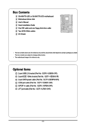
... cable (Part No. 12CF1-1CM001-32R) S/PDIF in cable (Part No. 12CR1-1SPDIN-01R) LPT port cable (Part No. 12CF1-1LP001-01R) - 6 - Box Contents GA-MA770-UD3 or GA-MA770-US3 motherboard Motherboard driver disk User's Manual Quick Installation Guide One IDE cable and one floppy disk drive cable Two SATA 3Gb/s cables I/O Shield • The box...
... cable (Part No. 12CF1-1CM001-32R) S/PDIF in cable (Part No. 12CR1-1SPDIN-01R) LPT port cable (Part No. 12CF1-1LP001-01R) - 6 - Box Contents GA-MA770-UD3 or GA-MA770-US3 motherboard Motherboard driver disk User's Manual Quick Installation Guide One IDE cable and one floppy disk drive cable Two SATA 3Gb/s cables I/O Shield • The box...
Manual
Page 7
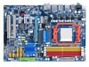
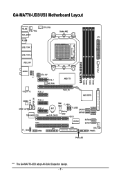
GA-MA770-UD3/US3 Motherboard Layout KB_MS SYS_FAN2 CPU_FAN Socket AM2 RCA_SPDIF ATX R_USB USB_1394_1 USB_1394_2 USB_LAN GA-MA770-UD3/US3 DDRII_1 DDRII_2 DDRII_3 DDRII_4 PWR_FAN F_AUDIO AUDIO ATX_12V PCIE_1 NB_FAN AMD 770 RTL8111C PCIE_2 CD_IN SPDIF_IN CODEC PCIE_3 SPDIF_OUT PCIE_4 TSB43AB23 PCI1 PCI2 F1_1394 COMA PCIE_16 IDE AMD SB700 Main BIOS F_USB1 BAT CLR_CMOS Backup BIOS F_USB2 SATAII1 SATAII3 SATAII0 CI SATAII2 IT8720 SATAII5 SATAII4 LPT FDD SYS_FAN1 F_PANEL PWR_LED "*" The GA-MA770-UD3 adopt All-Solid Capacitor design. - 7 -
GA-MA770-UD3/US3 Motherboard Layout KB_MS SYS_FAN2 CPU_FAN Socket AM2 RCA_SPDIF ATX R_USB USB_1394_1 USB_1394_2 USB_LAN GA-MA770-UD3/US3 DDRII_1 DDRII_2 DDRII_3 DDRII_4 PWR_FAN F_AUDIO AUDIO ATX_12V PCIE_1 NB_FAN AMD 770 RTL8111C PCIE_2 CD_IN SPDIF_IN CODEC PCIE_3 SPDIF_OUT PCIE_4 TSB43AB23 PCI1 PCI2 F1_1394 COMA PCIE_16 IDE AMD SB700 Main BIOS F_USB1 BAT CLR_CMOS Backup BIOS F_USB2 SATAII1 SATAII3 SATAII0 CI SATAII2 IT8720 SATAII5 SATAII4 LPT FDD SYS_FAN1 F_PANEL PWR_LED "*" The GA-MA770-UD3 adopt All-Solid Capacitor design. - 7 -
Manual
Page 9
...product, please verify that all cables and power connectors of your hardware components are connected tightly and securely. • When handling the motherboard, avoid touching any installation steps or have it on top of an antistatic pad or within the computer casing. • Do not ...within an electrostatic shielding container. • Before unplugging the power supply cable from the power outlet before installing or removing the motherboard or other hardware components. • When connecting hardware components to the internal connectors on the power, make sure they are connected...
...product, please verify that all cables and power connectors of your hardware components are connected tightly and securely. • When handling the motherboard, avoid touching any installation steps or have it on top of an antistatic pad or within the computer casing. • Do not ...within an electrostatic shielding container. • Before unplugging the power supply cable from the power outlet before installing or removing the motherboard or other hardware components. • When connecting hardware components to the internal connectors on the power, make sure they are connected...
Manual
Page 10
GA-MA770-UD3/US3 Motherboard - 10 - 1-2 Product Specifications CPU Hyper Transport Bus Chipset Memory Audio LAN ... TM X4 processor/ AMD PhenomTM X3 processor/AMD Athlon TM X2 processor/ AMD AthlonTM processor/AMD Sempron TM X2 processor/ AMD SempronTM processor (Go to GIGABYTE's website for the latest CPU support list.) 5200/2000 MT/s North Bridge: AMD 770 South Bridge: AMD SB700 4 x 1.8V DDR2 DIMM sockets supporting up to...
GA-MA770-UD3/US3 Motherboard - 10 - 1-2 Product Specifications CPU Hyper Transport Bus Chipset Memory Audio LAN ... TM X4 processor/ AMD PhenomTM X3 processor/AMD Athlon TM X2 processor/ AMD AthlonTM processor/AMD Sempron TM X2 processor/ AMD SempronTM processor (Go to GIGABYTE's website for the latest CPU support list.) 5200/2000 MT/s North Bridge: AMD 770 South Bridge: AMD SB700 4 x 1.8V DDR2 DIMM sockets supporting up to...
Manual
Page 12
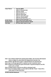
GA-MA770-UD3/US3 Motherboard - 12 - Unique Features Bundled Software Operating System Form Factor Support for @BIOS Support for Download Center Support for Q-Flash Support for ... CPU/system fan speed control function is supported will depend on the CPU/ system cooler you install. (Note 5) Available functions in EasyTune may differ by motherboard model. (Note 6) Due to the hardware limitation, you must install the AMD AM2+ Phenom TM Series CPU to enable support for Easy Energy Saver.
GA-MA770-UD3/US3 Motherboard - 12 - Unique Features Bundled Software Operating System Form Factor Support for @BIOS Support for Download Center Support for Q-Flash Support for ... CPU/system fan speed control function is supported will depend on the CPU/ system cooler you install. (Note 5) Available functions in EasyTune may differ by motherboard model. (Note 6) Due to the hardware limitation, you must install the AMD AM2+ Phenom TM Series CPU to enable support for Easy Energy Saver.

Manual
Page 13
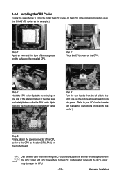
... overheating and damage of the CPU may occur. • Set the CPU host frequency in accordance with the CPU specifications. mended that the motherboard supports the CPU. (Go to GIGABYTE's website for the peripherals. Hardware Installation Locate the pin one of the Socket AM2 Socket A Small Triangle Marking Denotes CPU Pin One...
... overheating and damage of the CPU may occur. • Set the CPU host frequency in accordance with the CPU specifications. mended that the motherboard supports the CPU. (Go to GIGABYTE's website for the peripherals. Hardware Installation Locate the pin one of the Socket AM2 Socket A Small Triangle Marking Denotes CPU Pin One...
Manual
Page 14
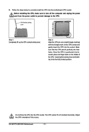
... the power outlet to prevent damage to correctly install the CPU into their holes. Make sure that the CPU pins fit perfectly into the motherboard CPU socket. Once the CPU is positioned into its socket, place one (small triangle marking) with the triangle mark on the middle of...to the CPU. The CPU cannot fit in if oriented incorrectly. CPU Socket Locking Lever Step 1: Completely lift up the CPU socket locking lever. GA-MA770-UD3/US3 Motherboard - 14 - Do not force the CPU into the fully locked position. Step 2: Align the CPU pin one finger down on the CPU socket...
... the power outlet to prevent damage to correctly install the CPU into their holes. Make sure that the CPU pins fit perfectly into the motherboard CPU socket. Once the CPU is positioned into its socket, place one (small triangle marking) with the triangle mark on the middle of...to the CPU. The CPU cannot fit in if oriented incorrectly. CPU Socket Locking Lever Step 1: Completely lift up the CPU socket locking lever. GA-MA770-UD3/US3 Motherboard - 14 - Do not force the CPU into the fully locked position. Step 2: Align the CPU pin one finger down on the CPU socket...
Manual
Page 15
1-3-2 Installing the CPU Cooler Follow the steps below to correctly install the CPU cooler on the CPU. (The following procedure uses the GIGABYTE cooler as the picture above shows) to lock into place. (Refer to your CPU cooler installation manual for instructions on installing the cooler.) Step 5: Finally, ... the retention frame. Step 2: Place the CPU cooler on the retention frame. Inadequately removing the CPU cooler may adhere to the mounting lug on the motherboard. Hardware Installation Step 3: Hook the CPU cooler clip to the CPU.
1-3-2 Installing the CPU Cooler Follow the steps below to correctly install the CPU cooler on the CPU. (The following procedure uses the GIGABYTE cooler as the picture above shows) to lock into place. (Refer to your CPU cooler installation manual for instructions on installing the cooler.) Step 5: Finally, ... the retention frame. Step 2: Place the CPU cooler on the retention frame. Inadequately removing the CPU cooler may adhere to the mounting lug on the motherboard. Hardware Installation Step 3: Hook the CPU cooler clip to the CPU.
Manual
Page 16
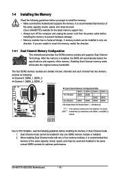
... the same capacity, brand, speed, and chips be used . (Go to prevent hardware damage. • Memory modules have a foolproof design. GA-MA770-UD3/US3 Motherboard - 16 - 1-4 Installing the Memory Read the following guidelines before installing the memory in Dual Channel mode . 1. Dual Channel mode cannot be ... list.) • Always turn off the computer and unplug the power cord from the power outlet before installing the memory to GIGABYTE's website for optimum performance. When enabling Dual Channel mode with two or four memory modules, it is recommended that you are ...
... the same capacity, brand, speed, and chips be used . (Go to prevent hardware damage. • Memory modules have a foolproof design. GA-MA770-UD3/US3 Motherboard - 16 - 1-4 Installing the Memory Read the following guidelines before installing the memory in Dual Channel mode . 1. Dual Channel mode cannot be ... list.) • Always turn off the computer and unplug the power cord from the power outlet before installing the memory to GIGABYTE's website for optimum performance. When enabling Dual Channel mode with two or four memory modules, it is recommended that you are ...

Manual
Page 17
... off the computer and unplug the power cord from the power outlet to prevent damage to the memory module. Place the memory module on this motherboard.
... off the computer and unplug the power cord from the power outlet to prevent damage to the memory module. Place the memory module on this motherboard.
Manual
Page 18
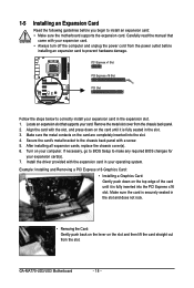
... turn off the computer and unplug the power cord from the power outlet before you begin to install an expansion card: • Make sure the motherboard supports the expansion card. After installing all expansion cards, replace the chassis cover(s). 6. If necessary, go to BIOS Setup to correctly install your operating system... sure the card is securely seated in the expansion slot. 1. Locate an expansion slot that came with the slot, and press down on your card. GA-MA770-UD3/US3 Motherboard - 18 - Carefully read the manual that supports your computer.
... turn off the computer and unplug the power cord from the power outlet before you begin to install an expansion card: • Make sure the motherboard supports the expansion card. After installing all expansion cards, replace the chassis cover(s). 6. If necessary, go to BIOS Setup to correctly install your operating system... sure the card is securely seated in the expansion slot. 1. Locate an expansion slot that came with the slot, and press down on your card. GA-MA770-UD3/US3 Motherboard - 18 - Carefully read the manual that supports your computer.

Manual
Page 19
.../2 keyboard. Optical S/PDIF Out Connector This connector provides digital audio out to an external audio system that your device and then remove it from the motherboard. • When removing the cable, pull it side to side to a back panel connector, first remove the cable from your audio system provides a n optical digital...
.../2 keyboard. Optical S/PDIF Out Connector This connector provides digital audio out to an external audio system that your device and then remove it from the motherboard. • When removing the cable, pull it side to side to a back panel connector, first remove the cable from your audio system provides a n optical digital...
Manual
Page 20
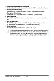
... audio jack for a headphone or 2-channel speaker. Use this audio jack to the instructions on setting up a 2/4/5.1/ 7.1-channel audio configuration in a 7.1-channel audio configuration. GA-MA770-UD3/US3 Motherboard - 20 - Mic In Jack (Pink) The default Mic in jack. Microphones must be connected to connect side speakers in Chapter 5, "Configuring 2/4/5.1/7.1-Channel Audio." Line Out...
... audio jack for a headphone or 2-channel speaker. Use this audio jack to the instructions on setting up a 2/4/5.1/ 7.1-channel audio configuration in a 7.1-channel audio configuration. GA-MA770-UD3/US3 Motherboard - 20 - Mic In Jack (Pink) The default Mic in jack. Microphones must be connected to connect side speakers in Chapter 5, "Configuring 2/4/5.1/7.1-Channel Audio." Line Out...

Manual
Page 21
..., make sure your devices are compliant with the connectors you wish to connect. • Before installing the devices, be sure to the connector on the motherboard. - 21 - Unplug the power cord from the power outlet to prevent damage to the devices. • After installing the device and before connecting external devices...
..., make sure your devices are compliant with the connectors you wish to connect. • Before installing the devices, be sure to the connector on the motherboard. - 21 - Unplug the power cord from the power outlet to prevent damage to the devices. • After installing the device and before connecting external devices...

Manual
Page 22
... power supply cable into pins under the protective cover when using a 2x12 power supply, remove the protective cover from the main power connector on the motherboard. When using a 2x10 power supply. 3 4 1 2 ATX_12V ATX_12V: Pin No. 1 2 3 4 Definition GND GND +12V +12V 13 1 24 12 ATX ATX: Pin No. 1 2 3 4 5 6 7 8 9 ...3.3V -12V GND PS_ON(soft On/Off) GND GND GND -5V +5V +5V +5V (Only for 2x12-pinATX) GND (Only for 2x12-pinATX) GA-MA770-UD3/US3 Motherboard - 22 - Before connecting the power connector, first make sure the power supply is turned off and all the components on the...
... power supply cable into pins under the protective cover when using a 2x12 power supply, remove the protective cover from the main power connector on the motherboard. When using a 2x10 power supply. 3 4 1 2 ATX_12V ATX_12V: Pin No. 1 2 3 4 Definition GND GND +12V +12V 13 1 24 12 ATX ATX: Pin No. 1 2 3 4 5 6 7 8 9 ...3.3V -12V GND PS_ON(soft On/Off) GND GND GND -5V +5V +5V +5V (Only for 2x12-pinATX) GND (Only for 2x12-pinATX) GA-MA770-UD3/US3 Motherboard - 22 - Before connecting the power connector, first make sure the power supply is turned off and all the components on the...
Manual
Page 23
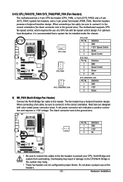
...are not configuration jumper blocks. Overheating may hang. • These fan headers are designed with fan speed control design. The motherboard supports CPU fan speed control, which requires the use of a CPU fan with color-coded power connector wires. When connecting ...Pin No. 1 2 3 4 Definition GND Speed Control Sense +5V 1 SYS_FAN2/PWR_FAN SYS_FAN2/PWR_FAN: Pin No. 3/4/5) CPU_FAN/SYS_FAN1/SYS_FAN2/PWR_FAN (Fan Headers) The motherboard has a 4-pin CPU fan header (CPU_FAN), a 3-pin (SYS_FAN2) and a 4-pin (SYS_FAN1) system fan headers, and a 3-pin power fan header (...
...are not configuration jumper blocks. Overheating may hang. • These fan headers are designed with fan speed control design. The motherboard supports CPU fan speed control, which requires the use of a CPU fan with color-coded power connector wires. When connecting ...Pin No. 1 2 3 4 Definition GND Speed Control Sense +5V 1 SYS_FAN2/PWR_FAN SYS_FAN2/PWR_FAN: Pin No. 3/4/5) CPU_FAN/SYS_FAN1/SYS_FAN2/PWR_FAN (Fan Headers) The motherboard has a 4-pin CPU fan header (CPU_FAN), a 3-pin (SYS_FAN2) and a 4-pin (SYS_FAN1) system fan headers, and a 3-pin power fan header (...
Manual
Page 24
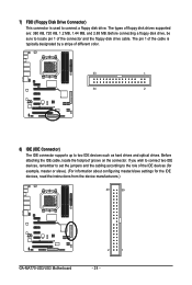
... (for example, master or slave). (For information about configuring master/slave settings for the IDE devices, read the instructions from the device manufacturers.) 40 39 GA-MA770-UD3/US3 Motherboard 2 1 - 24 - Before attaching the IDE cable, locate the foolproof groove on the connector. If you wish to connect two IDE devices, remember to set...
... (for example, master or slave). (For information about configuring master/slave settings for the IDE devices, read the instructions from the device manufacturers.) 40 39 GA-MA770-UD3/US3 Motherboard 2 1 - 24 - Before attaching the IDE cable, locate the foolproof groove on the connector. If you wish to connect two IDE devices, remember to set...


