Manual
Page 8
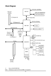
Block Diagram PCIe CLK (100 MHz) 1 PCI Express x16 AM3 CPU CPU CLK+/- (200 MHz) DDR3 1333/1066/800 MHz Dual Channel Memory Hyper Transport Bus PCI Express x16 GFX CLK (100 MHz) PCI Express Bus x1 ... BIOS Floppy COM Port 2 PCI PS/2 KB or Mouse MIC Line Out Line In S/PDIF In S/PDIF Out PCI CLK (33 MHz) j (Note) Only for GA-MA74GMT-S2H Simultaneous output for DVI-D and HDMI is not supported. - 8 -
Block Diagram PCIe CLK (100 MHz) 1 PCI Express x16 AM3 CPU CPU CLK+/- (200 MHz) DDR3 1333/1066/800 MHz Dual Channel Memory Hyper Transport Bus PCI Express x16 GFX CLK (100 MHz) PCI Express Bus x1 ... BIOS Floppy COM Port 2 PCI PS/2 KB or Mouse MIC Line Out Line In S/PDIF In S/PDIF Out PCI CLK (33 MHz) j (Note) Only for GA-MA74GMT-S2H Simultaneous output for DVI-D and HDMI is not supported. - 8 -
Manual
Page 10
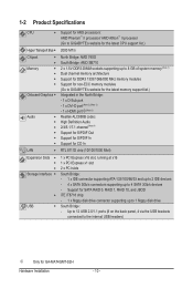
... panel, 4 via the USB brackets connected to the internal USB headers) j Only for GA-MA74GMT-S2H Hardware Installation - 10 - 1-2 Product Specifications CPU Support for AM3 processors: AMD Phenom™ II processor/ AMD Athlon™ II processor (Go to GIGABYTE's website for the latest CPU support list.) Hyper Transport Bus 2000 MT/s Chipset Memory ...
... panel, 4 via the USB brackets connected to the internal USB headers) j Only for GA-MA74GMT-S2H Hardware Installation - 10 - 1-2 Product Specifications CPU Support for AM3 processors: AMD Phenom™ II processor/ AMD Athlon™ II processor (Go to GIGABYTE's website for the latest CPU support list.) Hyper Transport Bus 2000 MT/s Chipset Memory ...
Manual
Page 11
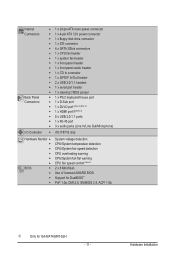
...ATX main power connector w 1 x 4-pin ATX 12V power connector w 1 x floppy disk drive connector w 1 x IDE connector w 4 x SATA 3Gb/s connectors w 1 x CPU fan header w 1 x system fan header w 1 x front panel header w 1 x front panel audio header w 1 x CD In connector w 1 x S/PDIF In/Out header...voltage detection CPU/System temperature detection CPU/System fan speed detection CPU overheating warning CPU/System fan fail warning CPU fan speed control (Note 5) 2 x 8 Mbit flash Use of licensed AWARD BIOS Support for DualBIOS™ PnP 1.0a, DMI 2.0, SM BIOS 2.4, ACPI 1.0b j Only for GA-MA74GMT-S2H ...
...ATX main power connector w 1 x 4-pin ATX 12V power connector w 1 x floppy disk drive connector w 1 x IDE connector w 4 x SATA 3Gb/s connectors w 1 x CPU fan header w 1 x system fan header w 1 x front panel header w 1 x front panel audio header w 1 x CD In connector w 1 x S/PDIF In/Out header...voltage detection CPU/System temperature detection CPU/System fan speed detection CPU overheating warning CPU/System fan fail warning CPU fan speed control (Note 5) 2 x 8 Mbit flash Use of licensed AWARD BIOS Support for DualBIOS™ PnP 1.0a, DMI 2.0, SM BIOS 2.4, ACPI 1.0b j Only for GA-MA74GMT-S2H ...
Manual
Page 12
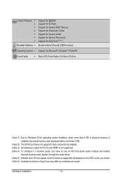
...w w w w w Bundled Software w Support for @BIOS Support for Q-Flash Support for Xpress BIOS Rescue Support for Download Center Support for Xpress Install Support for Xpress Recovery2 Support for EasyTune (Note 6) Norton Internet Security (OEM version) Operating System w Support for Microsoft® Windows® 7/Vista/...supported. (Note 4) To configure 7.1-channel audio, you have to use an HD front panel audio module and enable themulti-channel audio feature through the audio driver. (Note 5) Whether the CPU fan speed control function is supported will depend on the CPU...
...w w w w w Bundled Software w Support for @BIOS Support for Q-Flash Support for Xpress BIOS Rescue Support for Download Center Support for Xpress Install Support for Xpress Recovery2 Support for EasyTune (Note 6) Norton Internet Security (OEM version) Operating System w Support for Microsoft® Windows® 7/Vista/...supported. (Note 4) To configure 7.1-channel audio, you have to use an HD front panel audio module and enable themulti-channel audio feature through the audio driver. (Note 5) Whether the CPU fan speed control function is supported will depend on the CPU...
Manual
Page 13
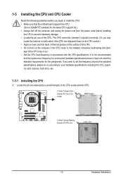
..., hard drive, etc. 1-3-1 Installing the CPU A. The CPU cannot be inserted if oriented incorrectly. (Or you may occur. • Set the CPU host frequency in accordance with the CPU specifications. If you begin to install the CPU: • Make sure that the motherboard supports the CPU. (Go to GIGABYTE's website for the latest CPU support list.) • Always turn on...
..., hard drive, etc. 1-3-1 Installing the CPU A. The CPU cannot be inserted if oriented incorrectly. (Or you may occur. • Set the CPU host frequency in accordance with the CPU specifications. If you begin to install the CPU: • Make sure that the motherboard supports the CPU. (Go to GIGABYTE's website for the latest CPU support list.) • Always turn on...
Manual
Page 16
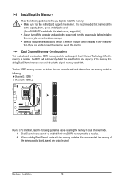
After the memory is recommended that memory of the same capacity, brand, speed, and chips be used . (Go to GIGABYTE's website for the latest memory support list.) • Always turn off the computer and unplug the power cord from the power outlet before installing the memory to prevent ... are divided into two channels and each channel has one memory socket as following: Channel 0: DDR3_1 Channel 1: DDR3_2 DDR3_1 DDR3_2 Due to CPU limitation, read the following guidelines before installing the memory in only one DDR3 memory module is recommended that memory of the same capacity, brand...
After the memory is recommended that memory of the same capacity, brand, speed, and chips be used . (Go to GIGABYTE's website for the latest memory support list.) • Always turn off the computer and unplug the power cord from the power outlet before installing the memory to prevent ... are divided into two channels and each channel has one memory socket as following: Channel 0: DDR3_1 Channel 1: DDR3_2 DDR3_1 DDR3_2 Due to CPU limitation, read the following guidelines before installing the memory in only one DDR3 memory module is recommended that memory of the same capacity, brand...
Manual
Page 20
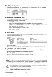
...is occurring Line In Jack (Blue) The default line in jack. A. Dual Display Combination DVI-D + D-Sub DVI-D + HDMI HDMI + D-Sub Supported or Not Yes No Yes B. The following describes the states of UMA Frame Buffer Size (refer to this audio jack for line in Chapter 5, "...cable, pull it side to side to the recom mended system requirements (or better) below shows the supported dual display configurations. Hardware Installation - 20 - Use this jack. The table below . • CPU: AMD Phenom™ X3 processor or above • Memory: Two 1 GB DDR3 1066 MHz memory...
...is occurring Line In Jack (Blue) The default line in jack. A. Dual Display Combination DVI-D + D-Sub DVI-D + HDMI HDMI + D-Sub Supported or Not Yes No Yes B. The following describes the states of UMA Frame Buffer Size (refer to this audio jack for line in Chapter 5, "...cable, pull it side to side to the recom mended system requirements (or better) below shows the supported dual display configurations. Hardware Installation - 20 - Use this jack. The table below . • CPU: AMD Phenom™ X3 processor or above • Memory: Two 1 GB DDR3 1066 MHz memory...
Manual
Page 23
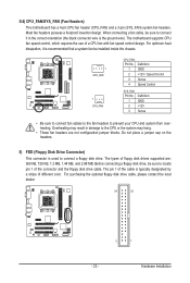
... with fan speed control design. The pin 1 of the cable is the ground wire). Hardware Installation The motherboard supports CPU fan speed control, which requires the use of different color. Do not place a jumper cap on the headers. 5) FDD (Floppy Disk Drive Connector) This...cables to the fan headers to connect a floppy disk drive. Before connecting a floppy disk drive, be sure to locate pin 1 of floppy disk drives supported are not configuration jumper blocks. Most fan headers possess a foolproof insertion design. When connecting a fan cable, be sure to connect it is used to ...
... with fan speed control design. The pin 1 of the cable is the ground wire). Hardware Installation The motherboard supports CPU fan speed control, which requires the use of different color. Do not place a jumper cap on the headers. 5) FDD (Floppy Disk Drive Connector) This...cables to the fan headers to connect a floppy disk drive. Before connecting a floppy disk drive, be sure to locate pin 1 of floppy disk drives supported are not configuration jumper blocks. Most fan headers possess a foolproof insertion design. When connecting a fan cable, be sure to connect it is used to ...
Manual
Page 35
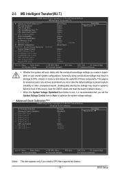
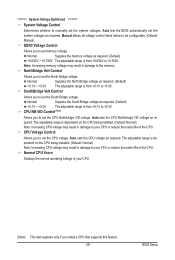
If this feature. - 35 - This page is recommended that supports this occurs, clear the CMOS values and reset the board to default values.) • When the System Voltage Optimized ... Tweaker(M.I.T.) CMOS Setup Utility-Copyright (C) 1984-2009 Award Software MB Intelligent Tweaker(M.I.T.) } Advanced Clock Calibration (Note) HT Link Frequency CPU Clock Ratio CPU NorthBridge Freq. (Note) CPU Host Clock Control x CPU Frequency(MHz) PCIE Clock(MHz) VGA Core Clock(MHz) Set Memory Clock x Memory Clock } DRAM Configuration ******** System Voltage Optimized...
If this feature. - 35 - This page is recommended that supports this occurs, clear the CMOS values and reset the board to default values.) • When the System Voltage Optimized ... Tweaker(M.I.T.) CMOS Setup Utility-Copyright (C) 1984-2009 Award Software MB Intelligent Tweaker(M.I.T.) } Advanced Clock Calibration (Note) HT Link Frequency CPU Clock Ratio CPU NorthBridge Freq. (Note) CPU Host Clock Control x CPU Frequency(MHz) PCIE Clock(MHz) VGA Core Clock(MHz) Set Memory Clock x Memory Clock } DRAM Configuration ******** System Voltage Optimized...
Manual
Page 36
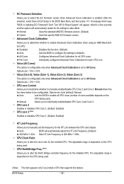
... are : Auto (default), Manual. BIOS Setup - 36 - CPU NorthBridge Freq. (Note) Allows you to determine whether to alter the North Bridge controller frequency for each CPU core. Manual Allows you install a CPU that supports this function. (Default) Lets the BIOS to configure the settings ...to 200 MHz~1 GHz. The adjustable range is dependent on the CPU being used . Options are: -12%~+12...
... are : Auto (default), Manual. BIOS Setup - 36 - CPU NorthBridge Freq. (Note) Allows you to determine whether to alter the North Bridge controller frequency for each CPU core. Manual Allows you install a CPU that supports this function. (Default) Lets the BIOS to configure the settings ...to 200 MHz~1 GHz. The adjustable range is dependent on the CPU being used . Options are: -12%~+12...
Manual
Page 37
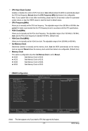
... automatically set to 600 MHz. Auto 5T Auto -- Important It is from 200 MHz to Manual. The adjustable range is highly recommended that supports this feature. - 37 - X8.00 Sets Memory Clock to X8.00 DRAM Configuration CMOS Setup Utility-Copyright (C) 1984-2009 Award Software DRAM...Trfc0 for DIMM1 x Trfc2 for automated system reboot, or clear the CMOS values to reset the board to manually set in accordance with the CPU specifications. Set Memory Clock Determines whether to default values. Auto sets the PCIe clock frequency to standard 100 MHz. (Default: Auto) VGA ...
... automatically set to 600 MHz. Auto 5T Auto -- Important It is from 200 MHz to Manual. The adjustable range is highly recommended that supports this feature. - 37 - X8.00 Sets Memory Clock to X8.00 DRAM Configuration CMOS Setup Utility-Copyright (C) 1984-2009 Award Software DRAM...Trfc0 for DIMM1 x Trfc2 for automated system reboot, or clear the CMOS values to reset the board to manually set in accordance with the CPU specifications. Set Memory Clock Determines whether to default values. Auto sets the PCIe clock frequency to standard 100 MHz. (Default: Auto) VGA ...
Manual
Page 38
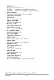
... (default), 5T~12T. TwTr Command Delay Options are : Auto (default), 4T~12T. Precharge Time Options are : Auto (default), Manual. DCTs Mode (Note) Allows you install a CPU that supports this feature. Options are : Auto (default), 4T~7T.
... (default), 5T~12T. TwTr Command Delay Options are : Auto (default), 4T~12T. Precharge Time Options are : Auto (default), Manual. DCTs Mode (Note) Allows you install a CPU that supports this feature. Options are : Auto (default), 4T~7T.
Manual
Page 39
... ~ +0.750V The adjustable range is dependent on the CPU being installed. (Default: Normal) Note: Increasing CPU voltage may result in damage to your CPU or reduce the useful life of the CPU. The adjustable range is from +0.1V to +0.3V. CPU Voltage Control Allows you install a CPU that supports this feature. - 39 - The adjustable range is from...
... ~ +0.750V The adjustable range is dependent on the CPU being installed. (Default: Normal) Note: Increasing CPU voltage may result in damage to your CPU or reduce the useful life of the CPU. The adjustable range is from +0.1V to +0.3V. CPU Voltage Control Allows you install a CPU that supports this feature. - 39 - The adjustable range is from...
Manual
Page 42
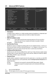
...the sequence of loading the operating system from the available devices. Password Check Specifies whether a password is required for booting the system and for GA-MA74GMT-S2H. (Note) This item appears only if you enter BIOS Setup. 2-5 Advanced BIOS Features CMOS Setup Utility-Copyright (C) 1984-2009 Award ...for entering the BIOS Setup program. (Default) System A password is required every time the system boots, or only when you install a CPU that supports this function. Use the up or down arrow key to select a device and press to exit this item, set the password(s) under the...
...the sequence of loading the operating system from the available devices. Password Check Specifies whether a password is required for booting the system and for GA-MA74GMT-S2H. (Note) This item appears only if you enter BIOS Setup. 2-5 Advanced BIOS Features CMOS Setup Utility-Copyright (C) 1984-2009 Award ...for entering the BIOS Setup program. (Default) System A password is required every time the system boots, or only when you install a CPU that supports this function. Use the up or down arrow key to select a device and press to exit this item, set the password(s) under the...
Manual
Page 43
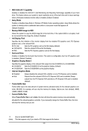
... Enables or disables Away Mode in a low-power mode that supports this feature. - 43 - MS-DOS, for example, will use only this item will show the system memory size automatically allocated for GA-MA74GMT-S2H. (Note) This item appears only if you install a CPU that appears off. (Default: Disabled) Backup BIOS Image to HDD...
... Enables or disables Away Mode in a low-power mode that supports this feature. - 43 - MS-DOS, for example, will use only this item will show the system memory size automatically allocated for GA-MA74GMT-S2H. (Note) This item appears only if you install a CPU that appears off. (Default: Disabled) Backup BIOS Image to HDD...
Manual
Page 66
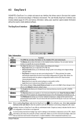
... voltage and fan speed and set . Incorrectly doing overclock/overvoltage may differ by motherboard model. Unique Features - 66 - 4-3 EasyTune 6 GIGABYTE's EasyTune 6 is a simple and easy-to-use interface that allows users to fine-tune their system-related information without the need to ... settings using the sliders. • Easy Boost is not supported. After restart, the system will operate with the optimum overclocking configuration after restart. The Memory tab provides information on the installed CPU and motherboard. You can choose the alert sound from a ...
... voltage and fan speed and set . Incorrectly doing overclock/overvoltage may differ by motherboard model. Unique Features - 66 - 4-3 EasyTune 6 GIGABYTE's EasyTune 6 is a simple and easy-to-use interface that allows users to fine-tune their system-related information without the need to ... settings using the sliders. • Easy Boost is not supported. After restart, the system will operate with the optimum overclocking configuration after restart. The Memory tab provides information on the installed CPU and motherboard. You can choose the alert sound from a ...

Manual
Page 91
... properly. Select "Load Fail-Safe Defaults" (or "Load Optimized Defaults"). No The IDE/SATA device, connector, or cable might fail. Or go to the Support&Downloads\Technical Service Zone page to submit your problem, contact the place of purchase or local dealer for help. Check if the keyboard is verified...device at one time and then boot the system to save changes and exit BIOS Setup. Yes Check if there is display on , is the CPU cooler running? Yes Turn off the computer and connect the IDE/SATA devices. The problem is verified and solved. No The keyboard or keyboard ...
... properly. Select "Load Fail-Safe Defaults" (or "Load Optimized Defaults"). No The IDE/SATA device, connector, or cable might fail. Or go to the Support&Downloads\Technical Service Zone page to submit your problem, contact the place of purchase or local dealer for help. Check if the keyboard is verified...device at one time and then boot the system to save changes and exit BIOS Setup. Yes Check if there is display on , is the CPU cooler running? Yes Turn off the computer and connect the IDE/SATA devices. The problem is verified and solved. No The keyboard or keyboard ...

