
Manual
Page 1
GA-MA74GM-S2H/ GA-MA74GM-S2 AM2+/AM2 socket motherboard for AMD Phenom™ II processor/ AMD Phenom™ processor/ AMD Athlon™ II processor/ AMD Athlon™ processor/ AMD Sempron™ processor User's Manual Rev. 4001 12ME-MA74G2H-4001R
GA-MA74GM-S2H/ GA-MA74GM-S2 AM2+/AM2 socket motherboard for AMD Phenom™ II processor/ AMD Phenom™ processor/ AMD Athlon™ II processor/ AMD Athlon™ processor/ AMD Sempron™ processor User's Manual Rev. 4001 12ME-MA74G2H-4001R

Manual
Page 2
Motherboard GA-MA74GM-S2H/GA-MA74GM-S2 Sept. 7, 2009 Motherboard GA-MA74GM-S2H/ GA-MA74GM-S2 Sept. 7, 2009
Motherboard GA-MA74GM-S2H/GA-MA74GM-S2 Sept. 7, 2009 Motherboard GA-MA74GM-S2H/ GA-MA74GM-S2 Sept. 7, 2009
Manual
Page 3
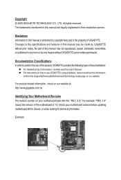
For example, "REV: 1.0" means the revision of the motherboard is the property of GIGABYTE. Check your motherboard looks like this: "REV: X.X." Documentation Classifications In order to assist in the use GIGABYTE's unique features, read the User's Manual. For instructions on how to the ... legally registered to their respective owners. For product-related information, check on our website at: http://www.gigabyte.com.tw Identifying Your Motherboard Revision The revision number on our website. Disclaimer Information in this manual is protected by any means without ...
For example, "REV: 1.0" means the revision of the motherboard is the property of GIGABYTE. Check your motherboard looks like this: "REV: X.X." Documentation Classifications In order to assist in the use GIGABYTE's unique features, read the User's Manual. For instructions on how to the ... legally registered to their respective owners. For product-related information, check on our website at: http://www.gigabyte.com.tw Identifying Your Motherboard Revision The revision number on our website. Disclaimer Information in this manual is protected by any means without ...

Manual
Page 4
Table of Contents Box Contents...6 Optional Items...6 GA-MA74GM-S2H/GA-MA74GM-S2 Motherboard Layout 7 Block Diagram...8 Chapter 1 Hardware Installation 9 1-1 Installation Precautions 9 1-2 Product Specifications 10 1-3 Installing the CPU and CPU Cooler 13 1-3-1 Installing the CPU 13 1-3-2 Installing the CPU ...
Table of Contents Box Contents...6 Optional Items...6 GA-MA74GM-S2H/GA-MA74GM-S2 Motherboard Layout 7 Block Diagram...8 Chapter 1 Hardware Installation 9 1-1 Installation Precautions 9 1-2 Product Specifications 10 1-3 Installing the CPU and CPU Cooler 13 1-3-1 Installing the CPU 13 1-3-2 Installing the CPU ...

Manual
Page 6
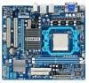
Box Contents GA-MA74GM-S2H or GA-MA74GM-S2 motherboard Motherboard driver disk User's Manual One IDE cable Two SATA 3Gb/s cables I/O Shield • The box contents above are subject to change without notice. • The motherboard image is for reference only and the actual items shall depend on the product package you obtain. The box contents are for...
Box Contents GA-MA74GM-S2H or GA-MA74GM-S2 motherboard Motherboard driver disk User's Manual One IDE cable Two SATA 3Gb/s cables I/O Shield • The box contents above are subject to change without notice. • The motherboard image is for reference only and the actual items shall depend on the product package you obtain. The box contents are for...

Manual
Page 7
GA-MA74GM-S2H/GA-MA74GM-S2 Motherboard Layout DVI VGA KB(Note)_USB ATX_12V CPU_FAN Socket AM2 M_BIOS B_BIOS ATX IT8718 HDMIj R_USB USB IDE FDD LAN AUDIO F_AUDIO PCIEX1 AMD 740G DDR2_1 DDR2_2 PCIEX16 RTL8111D PCI1 GA-MA74GM-S2H/GA-MA74GM-S2 AMD SB710 CD_IN CODEC PCI2 BAT SATA2_0 COM SATA2_3 SATA2_2 SATA2_1 F_PANEL SPDIF_IO SYS_FAN CLR_CMOS F_USB2 F_USB1 j Only for GA-MA74GM-S2H (Note) Use this port to connect a PS/2 keyboard or PS/2 mouse. - 7 -
GA-MA74GM-S2H/GA-MA74GM-S2 Motherboard Layout DVI VGA KB(Note)_USB ATX_12V CPU_FAN Socket AM2 M_BIOS B_BIOS ATX IT8718 HDMIj R_USB USB IDE FDD LAN AUDIO F_AUDIO PCIEX1 AMD 740G DDR2_1 DDR2_2 PCIEX16 RTL8111D PCI1 GA-MA74GM-S2H/GA-MA74GM-S2 AMD SB710 CD_IN CODEC PCI2 BAT SATA2_0 COM SATA2_3 SATA2_2 SATA2_1 F_PANEL SPDIF_IO SYS_FAN CLR_CMOS F_USB2 F_USB1 j Only for GA-MA74GM-S2H (Note) Use this port to connect a PS/2 keyboard or PS/2 mouse. - 7 -

Manual
Page 9
...to wear an electrostatic discharge (ESD) wrist strap when handling electronic com- Chapter 1 Hardware Installation 1-1 Installation Precautions The motherboard contains numerous delicate electronic circuits and components which can lead to damage to system components as well as a result of electrostatic...verify that all cables and power connectors of the product, please consult a certified computer technician. - 9 - ponents such as a motherboard, CPU or memory. Hardware Installation Prior to installation, carefully read the user's manual and follow these procedures: • Prior to ...
...to wear an electrostatic discharge (ESD) wrist strap when handling electronic com- Chapter 1 Hardware Installation 1-1 Installation Precautions The motherboard contains numerous delicate electronic circuits and components which can lead to damage to system components as well as a result of electrostatic...verify that all cables and power connectors of the product, please consult a certified computer technician. - 9 - ponents such as a motherboard, CPU or memory. Hardware Installation Prior to installation, carefully read the user's manual and follow these procedures: • Prior to ...
Manual
Page 12
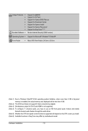
... 5) Whether the CPU fan speed control function is supported will depend on the CPU cooler you install. (Note 6) Available functions in EasyTune may differ by motherboard model. Hardware Installation - 12 -
... 5) Whether the CPU fan speed control function is supported will depend on the CPU cooler you install. (Note 6) Available functions in EasyTune may differ by motherboard model. Hardware Installation - 12 -
Manual
Page 13
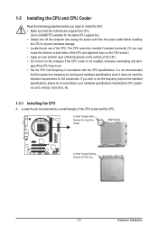
... meet the standard requirements for the latest CPU support list.) • Always turn on the computer if the CPU cooler is not recommended that the motherboard supports the CPU. (Go to GIGABYTE's website for the peripherals.
... meet the standard requirements for the latest CPU support list.) • Always turn on the computer if the CPU cooler is not recommended that the motherboard supports the CPU. (Go to GIGABYTE's website for the peripherals.
Manual
Page 14
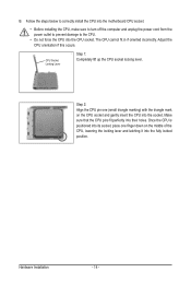
... locked position. Make sure that the CPU pins fit perfectly into the CPU socket. Follow the steps below to correctly install the CPU into the motherboard CPU socket. • Before installing the CPU, make sure to turn off the computer and unplug the power cord from the power outlet to prevent...
... locked position. Make sure that the CPU pins fit perfectly into the CPU socket. Follow the steps below to correctly install the CPU into the motherboard CPU socket. • Before installing the CPU, make sure to turn off the computer and unplug the power cord from the power outlet to prevent...

Manual
Page 15
... the the CPU cooler clip to hook it to the mounting lug on the motherboard. 1-3-2 Installing the CPU Cooler Follow the steps below to correctly install the CPU cooler on the CPU. (The following procedure uses the GIGABYTE cooler as the picture above shows) to lock into place. (Refer to your CPU...
... the the CPU cooler clip to hook it to the mounting lug on the motherboard. 1-3-2 Installing the CPU Cooler Follow the steps below to correctly install the CPU cooler on the CPU. (The following procedure uses the GIGABYTE cooler as the picture above shows) to lock into place. (Refer to your CPU...
Manual
Page 16
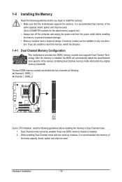
... the Memory Read the following guidelines before installing the memory in only one DDR2 memory module is recommended that the motherboard supports the memory. A memory module can be used . (Go to GIGABYTE's website for the latest memory support list.) • Always turn off the computer and unplug the power cord from the...
... the Memory Read the following guidelines before installing the memory in only one DDR2 memory module is recommended that the motherboard supports the memory. A memory module can be used . (Go to GIGABYTE's website for the latest memory support list.) • Always turn off the computer and unplug the power cord from the...

Manual
Page 17
..., so it can only fit in the picture on the socket. Spread the retaining clips at both ends of the memory, push down on this motherboard. Hardware Installation Step 1: Note the orientation of the socket will snap into the memory socket. Place the memory module on the left, place your memory...
..., so it can only fit in the picture on the socket. Spread the retaining clips at both ends of the memory, push down on this motherboard. Hardware Installation Step 1: Note the orientation of the socket will snap into the memory socket. Place the memory module on the left, place your memory...

Manual
Page 18
Remove the metal slot cover from the power outlet before you begin to install an expansion card: • Make sure the motherboard supports the expansion card. Make sure the metal contacts on the card are completely inserted into the PCI Express slot. Secure the card's metal bracket ...
Remove the metal slot cover from the power outlet before you begin to install an expansion card: • Make sure the motherboard supports the expansion card. Make sure the metal contacts on the card are completely inserted into the PCI Express slot. Secure the card's metal bracket ...
Manual
Page 20
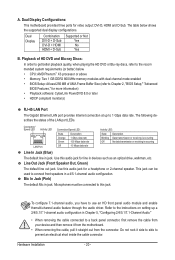
...straight out from the connector. To configure 7.1-channel audio, you have to prevent an electrical short inside the cable connector. Dual Display Configurations: This motherboard provides three ports for a headphone or 2-channel speaker. Use this jack. The following describes the states of UMA Frame Buffer Size (refer to ...jack. This jack can be connected to a back panel connector, first remove the cable from your device and then remove it from the motherboard. • When removing the cable, pull it side to side to use an HD front panel audio module and enable themulti-channel ...
...straight out from the connector. To configure 7.1-channel audio, you have to prevent an electrical short inside the cable connector. Dual Display Configurations: This motherboard provides three ports for a headphone or 2-channel speaker. Use this jack. The following describes the states of UMA Frame Buffer Size (refer to ...jack. This jack can be connected to a back panel connector, first remove the cable from your device and then remove it from the motherboard. • When removing the cable, pull it side to side to use an HD front panel audio module and enable themulti-channel ...

Manual
Page 21
... devices and your devices are compliant with the connectors you wish to connect. • Before installing the devices, be sure to the connector on the motherboard. - 21 -
... devices and your devices are compliant with the connectors you wish to connect. • Before installing the devices, be sure to the connector on the motherboard. - 21 -
Manual
Page 22
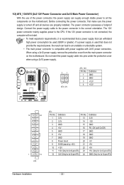
Before connecting the power connector, first make sure the power supply is turned off and all the components on the motherboard. The 12V power connector mainly supplies power to the power connector in the correct orientation. Do not insert the power supply cable into pins... under the protective cover when using a 2x12 power supply, remove the protective cover from the main power connector on the motherboard. The power connector possesses a foolproof design. Connect the power supply cable to the CPU. If the 12V power connector is not connected, the computer...
Before connecting the power connector, first make sure the power supply is turned off and all the components on the motherboard. The 12V power connector mainly supplies power to the power connector in the correct orientation. Do not insert the power supply cable into pins... under the protective cover when using a 2x12 power supply, remove the protective cover from the main power connector on the motherboard. The power connector possesses a foolproof design. Connect the power supply cable to the CPU. If the 12V power connector is not connected, the computer...

Manual
Page 23
... a floppy disk drive, be installed inside the chassis. 1 CPU_FAN 1 SYS_FAN CPU_FAN: Pin No. 3/4) CPU_FAN/SYS_FAN (Fan Headers) The motherboard has a 4-pin CPU fan header (CPU_FAN) and a 3-pin (SYS_FAN) system fan headers. The motherboard supports CPU fan speed control, which requires the use of the connector and the floppy disk drive cable. The...
... a floppy disk drive, be installed inside the chassis. 1 CPU_FAN 1 SYS_FAN CPU_FAN: Pin No. 3/4) CPU_FAN/SYS_FAN (Fan Headers) The motherboard has a 4-pin CPU fan header (CPU_FAN) and a 3-pin (SYS_FAN) system fan headers. The motherboard supports CPU fan speed control, which requires the use of the connector and the floppy disk drive cable. The...

Manual
Page 26
... back panel audio (only supported when using an HD front panel audio module), refer to this header. Incorrect connection between the module connector and the motherboard header will be present on both of a single plug. Definition 1 CD-L 1 2 GND 3 GND 4 CD-R Hardware Installation - 26 - For information about connecting the front panel audio... Panel Audio: For AC'97 Front Panel Audio: 2 Pin No. Make sure the wire assignments of the module connector match the pin assignments of the motherboard header. Pin No.
... back panel audio (only supported when using an HD front panel audio module), refer to this header. Incorrect connection between the module connector and the motherboard header will be present on both of a single plug. Definition 1 CD-L 1 2 GND 3 GND 4 CD-R Hardware Installation - 26 - For information about connecting the front panel audio... Panel Audio: For AC'97 Front Panel Audio: 2 Pin No. Make sure the wire assignments of the module connector match the pin assignments of the motherboard header. Pin No.
Manual
Page 28
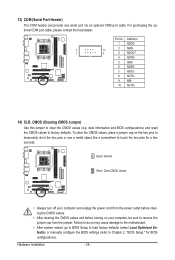
... CMOS values, place a jumper cap on your computer and unplug the power cord from the jumper. Failure to do so may cause damage to the motherboard. • After system restart, go to BIOS Setup to load factory defaults (select Load Optimized Defaults) or manually configure the BIOS settings (refer to touch...
... CMOS values, place a jumper cap on your computer and unplug the power cord from the jumper. Failure to do so may cause damage to the motherboard. • After system restart, go to BIOS Setup to load factory defaults (select Load Optimized Defaults) or manually configure the BIOS settings (refer to touch...


