Manual
Page 3
... on/from the Support&Downloads\Motherboard\Technology Guide page on your motherboard revision before updating motherboard BIOS, drivers, or when looking for technical information. Example: Check your motherboard looks like this manual is protected by GIGABYTE without GIGABYTE's prior written permission. Copyright © 2009 GIGA-BYTE TECHNOLOGY CO., LTD. All rights reserved. The...
... on/from the Support&Downloads\Motherboard\Technology Guide page on your motherboard revision before updating motherboard BIOS, drivers, or when looking for technical information. Example: Check your motherboard looks like this manual is protected by GIGABYTE without GIGABYTE's prior written permission. Copyright © 2009 GIGA-BYTE TECHNOLOGY CO., LTD. All rights reserved. The...
Manual
Page 4
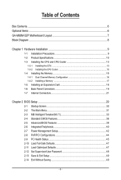
Table of Contents Box Contents...6 Optional Items...6 GA-M68M-S2P Motherboard Layout 7 Block Diagram...8 Chapter 1 Hardware Installation 9 1-1 Installation Precautions 9 1-2 Product Specifications 10 1-3 Installing the CPU and CPU Cooler ...1-5 Installing an Expansion Card 18 1-6 Back Panel Connectors 19 1-7 Internal Connectors 21 Chapter 2 BIOS Setup 29 2-1 Startup Screen 30 2-2 The Main Menu 31 2-3 MB Intelligent Tweaker(M.I.T 33 2-4 Standard CMOS Features 36 2-5 Advanced BIOS Features 38 2-6 Integrated Peripherals 40 2-7 Power Management Setup 42 2-8 PnP/PCI Configurations 44 ...
Table of Contents Box Contents...6 Optional Items...6 GA-M68M-S2P Motherboard Layout 7 Block Diagram...8 Chapter 1 Hardware Installation 9 1-1 Installation Precautions 9 1-2 Product Specifications 10 1-3 Installing the CPU and CPU Cooler ...1-5 Installing an Expansion Card 18 1-6 Back Panel Connectors 19 1-7 Internal Connectors 21 Chapter 2 BIOS Setup 29 2-1 Startup Screen 30 2-2 The Main Menu 31 2-3 MB Intelligent Tweaker(M.I.T 33 2-4 Standard CMOS Features 36 2-5 Advanced BIOS Features 38 2-6 Integrated Peripherals 40 2-7 Power Management Setup 42 2-8 PnP/PCI Configurations 44 ...
Manual
Page 5
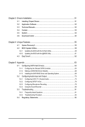
... 52 3-3 Technical Manuals 52 3-4 Contact...53 3-5 System...53 3-6 Download Center 54 Chapter 4 Unique Features 55 4-1 Xpress Recovery2 55 4-2 BIOS Update Utilities 58 4-2-1 Updating the BIOS with the Q-Flash Utility 58 4-2-2 Updating the BIOS with the @BIOS Utility 61 4-3 EasyTune 6...62 Chapter 5 Appendix...63 5-1 Configuring SATA Hard Drive(s 63 5-1-1 Configuring the Onboard SATA Controller 63...
... 52 3-3 Technical Manuals 52 3-4 Contact...53 3-5 System...53 3-6 Download Center 54 Chapter 4 Unique Features 55 4-1 Xpress Recovery2 55 4-2 BIOS Update Utilities 58 4-2-1 Updating the BIOS with the Q-Flash Utility 58 4-2-2 Updating the BIOS with the @BIOS Utility 61 4-3 EasyTune 6...62 Chapter 5 Appendix...63 5-1 Configuring SATA Hard Drive(s 63 5-1-1 Configuring the Onboard SATA Controller 63...
Manual
Page 8
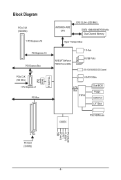
Block Diagram PCIe CLK (100 MHz) 1 PCI Express x16 PCI Express x16 PCI Express Bus x1 PCIe CLK (100 MHz) 1 PCI Express x1 PCI Bus LAN RJ45 RTL8211CL AM3/AM2+/AM2 CPU CPU CLK+/- (200 MHz) DDR2 1066/800/667/533 MHz Dual Channel Memory Hyper Transport Bus NVIDIA® GeForce 7025/nForce 630a 1 D-Sub 8 USB Ports ATA-133/100/66/33 IDE Channel 4 SATA 3Gb/s LPC Bus IT8718 Dual BIOS Floppy COM Port LPT Port CODEC PS/2 KB/Mouse MIC Line Out Line In S/PDIF In S/PDIF Out 2 PCI PCI CLK (33 MHz) - 8 -
Block Diagram PCIe CLK (100 MHz) 1 PCI Express x16 PCI Express x16 PCI Express Bus x1 PCIe CLK (100 MHz) 1 PCI Express x1 PCI Bus LAN RJ45 RTL8211CL AM3/AM2+/AM2 CPU CPU CLK+/- (200 MHz) DDR2 1066/800/667/533 MHz Dual Channel Memory Hyper Transport Bus NVIDIA® GeForce 7025/nForce 630a 1 D-Sub 8 USB Ports ATA-133/100/66/33 IDE Channel 4 SATA 3Gb/s LPC Bus IT8718 Dual BIOS Floppy COM Port LPT Port CODEC PS/2 KB/Mouse MIC Line Out Line In S/PDIF In S/PDIF Out 2 PCI PCI CLK (33 MHz) - 8 -

Manual
Page 11
... port w 1 x D-Sub port w 1 x parallel port w 1 x serial port w 4 x USB 2.0/1.1 ports w 1 x RJ-45 port w 3 x audio jacks (Line In/Line Out/Microphone) I/O Controller w iTE IT8718 chip Hardware Monitor w w w w w w BIOS w w w w System voltage detection CPU/System temperature detection CPU/System fan speed detection CPU/System overheating warning CPU/System fan fail warning CPU fan speed control...
... port w 1 x D-Sub port w 1 x parallel port w 1 x serial port w 4 x USB 2.0/1.1 ports w 1 x RJ-45 port w 3 x audio jacks (Line In/Line Out/Microphone) I/O Controller w iTE IT8718 chip Hardware Monitor w w w w w w BIOS w w w w System voltage detection CPU/System temperature detection CPU/System fan speed detection CPU/System overheating warning CPU/System fan fail warning CPU fan speed control...

Manual
Page 12
Hardware Installation - 12 - Unique Features w w w w w w w Bundled Software w Support for @BIOS Support for Q-Flash Support for Xpress BIOS Rescue Support for Download Center Support for Xpress Install Support for Xpress Recovery2 Support for EasyTune (Note 4) Norton Internet Security (OEM version) Operating System w Support ...
Hardware Installation - 12 - Unique Features w w w w w w w Bundled Software w Support for @BIOS Support for Q-Flash Support for Xpress BIOS Rescue Support for Download Center Support for Xpress Install Support for Xpress Recovery2 Support for EasyTune (Note 4) Norton Internet Security (OEM version) Operating System w Support ...
Manual
Page 16
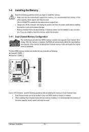
...memory mode will automatically detect the specifications and capacity of the same capacity, brand, speed, and chips be used . (Go to GIGABYTE's website for the latest memory support list.) • Always turn off the computer and unplug the power cord from the power ... direction. 1-4-1 Dual Channel Memory Configuration This motherboard provides two DDR2 memory sockets and supports Dual Channel Technology. It is installed, the BIOS will double the original memory bandwidth. 1-4 Installing the Memory Read the following guidelines before you are divided into two channels as following...
...memory mode will automatically detect the specifications and capacity of the same capacity, brand, speed, and chips be used . (Go to GIGABYTE's website for the latest memory support list.) • Always turn off the computer and unplug the power cord from the power ... direction. 1-4-1 Dual Channel Memory Configuration This motherboard provides two DDR2 memory sockets and supports Dual Channel Technology. It is installed, the BIOS will double the original memory bandwidth. 1-4 Installing the Memory Read the following guidelines before you are divided into two channels as following...
Manual
Page 18
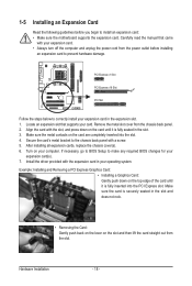
...: • Installing a Graphics Card: Gently push down on the card are completely inserted into the PCI Express slot. If necessary, go to BIOS Setup to make any required BIOS changes for your expansion card in the slot and does not rock. • Removing the Card: Gently push back on the lever on...
...: • Installing a Graphics Card: Gently push down on the card are completely inserted into the PCI Express slot. If necessary, go to BIOS Setup to make any required BIOS changes for your expansion card in the slot and does not rock. • Removing the Card: Gently push back on the lever on...
Manual
Page 25
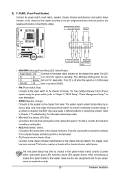
...different patterns to the hard drive activity LED on the chassis front panel. When connecting your system using the power switch (refer to Chapter 2, "BIOS Setup," "Power Management Setup," for information about beep codes. • HD (Hard Drive Activity LED, Blue) Connects to indicate the problem.... keeps blinking when the sys- S1 Blinking tem is detected at system startup. The LED is on when the hard drive is detected, the BIOS may differ by issuing a beep code. Note the positive and negative pins before connecting the cables. RESRES+ CICI+ PWR+ PWR- Refer to...
...different patterns to the hard drive activity LED on the chassis front panel. When connecting your system using the power switch (refer to Chapter 2, "BIOS Setup," "Power Management Setup," for information about beep codes. • HD (Hard Drive Activity LED, Blue) Connects to indicate the problem.... keeps blinking when the sys- S1 Blinking tem is detected at system startup. The LED is on when the hard drive is detected, the BIOS may differ by issuing a beep code. Note the positive and negative pins before connecting the cables. RESRES+ CICI+ PWR+ PWR- Refer to...
Manual
Page 28
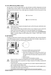
...the negative side (-) of the battery (the positive side should face up). • Used batteries must be sure to keep the values (such as BIOS configurations, date, and time information) in the CMOS when the computer is replaced with an incorrect model. • Contact the place of purchase or.... • Always turn off your computer and unplug the power cord. 2. Turn off . date information and BIOS configurations) and reset the CMOS values to touch the two pins for BIOS configurations). 14) BAT (Battery) The battery provides power to remove the jumper cap from the battery holder and ...
...the negative side (-) of the battery (the positive side should face up). • Used batteries must be sure to keep the values (such as BIOS configurations, date, and time information) in the CMOS when the computer is replaced with an incorrect model. • Contact the place of purchase or.... • Always turn off your computer and unplug the power cord. 2. Turn off . date information and BIOS configurations) and reset the CMOS values to touch the two pins for BIOS configurations). 14) BAT (Battery) The battery provides power to remove the jumper cap from the battery holder and ...
Manual
Page 29
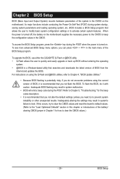
... Chapter 5, "Troubleshooting," for how to Chapter 4, "BIOS Update Utilities." • Because BIOS flashing is potentially risky, if you not flash the BIOS. BIOS Setup For instructions on . To upgrade the BIOS, use either the GIGABYTE Q-Flash or @BIOS utility. • Q-Flash allows the user to activate certain system features. BIOS includes a BIOS Setup program that searches and downloads the...
... Chapter 5, "Troubleshooting," for how to Chapter 4, "BIOS Update Utilities." • Because BIOS flashing is potentially risky, if you not flash the BIOS. BIOS Setup For instructions on . To upgrade the BIOS, use either the GIGABYTE Q-Flash or @BIOS utility. • Q-Flash allows the user to activate certain system features. BIOS includes a BIOS Setup program that searches and downloads the...
Manual
Page 30
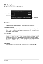
... needed. : Q-FLASH Press the key to access the Q-Flash utility directly without entering BIOS Setup. M68M-S2P D5 . . . . : BIOS Setup : XpressRecovery2 : Boot Menu : Qflash 11/13/2009-NF-MCP68-6A61KG0GC-00 Function Keys Function Keys: : BIOS SETUP Press the key to enter BIOS Setup or to access the Q-Flash utility in Boot Menu is effective for...
... needed. : Q-FLASH Press the key to access the Q-Flash utility directly without entering BIOS Setup. M68M-S2P D5 . . . . : BIOS Setup : XpressRecovery2 : Boot Menu : Qflash 11/13/2009-NF-MCP68-6A61KG0GC-00 Function Keys Function Keys: : BIOS SETUP Press the key to enter BIOS Setup or to access the Q-Flash utility in Boot Menu is effective for...

Manual
Page 31
... the right side of the submenu. • If you do not find the settings you enter the BIOS Setup program, the Main Menu (as usual, select the Load Optimized Defaults item to set your system... Without Saving Select Item F10: Save & Exit Setup Change CPU's Clock & Voltage BIOS Setup Program Function Keys Move the selection bar to select an item Execute command or enter the submenu Main...screen description of a highlighted setup option is not stable as shown below) appears on the screen. BIOS Setup Submenu Help While in the Main Menu or a submenu, press + to access more advanced options...
... the right side of the submenu. • If you do not find the settings you enter the BIOS Setup program, the Main Menu (as usual, select the Load Optimized Defaults item to set your system... Without Saving Select Item F10: Save & Exit Setup Change CPU's Clock & Voltage BIOS Setup Program Function Keys Move the selection bar to select an item Execute command or enter the submenu Main...screen description of a highlighted setup option is not stable as shown below) appears on the screen. BIOS Setup Submenu Help While in the Main Menu or a submenu, press + to access more advanced options...
Manual
Page 32
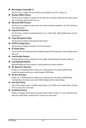
... time and date, hard drive types, floppy disk drive types, and the type of errors that stop the system boot, etc. Advanced BIOS Features Use this menu to configure the device boot order, advanced features available on the CPU, and the primary display adapter. Integrated Peripherals ...configure the system's PCI & PnP resources. PC Health Status Use this task.) Exit Without Saving Abandon all the changes made in BIOS Setup. Set User Password Change, set , or disable password. A user password only allows you to restrict access to the system and...
... time and date, hard drive types, floppy disk drive types, and the type of errors that stop the system boot, etc. Advanced BIOS Features Use this menu to configure the device boot order, advanced features available on the CPU, and the primary display adapter. Integrated Peripherals ...configure the system's PCI & PnP resources. PC Health Status Use this task.) Exit Without Saving Abandon all the changes made in BIOS Setup. Set User Password Change, set , or disable password. A user password only allows you to restrict access to the system and...

Manual
Page 33
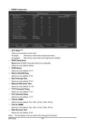
.... X4.00 Sets Memory Clock to X2.66. DDR 667 Sets Memory Clock to DDR 800. - 33 - DDR 800 Sets Memory Clock to DDR 667. BIOS Setup Incorrectly doing overclock may result in damage to CPU, chipset, or memory and reduce the useful life of these components. Manual allows the memory... the system will work stably with the overclock settings you use an AM3/AM2+ CPU: X2.00 Sets Memory Clock to X2.00. Auto lets BIOS automatically set the memory clock as required.
.... X4.00 Sets Memory Clock to X2.66. DDR 667 Sets Memory Clock to DDR 800. - 33 - DDR 800 Sets Memory Clock to DDR 667. BIOS Setup Incorrectly doing overclock may result in damage to CPU, chipset, or memory and reduce the useful life of these components. Manual allows the memory... the system will work stably with the overclock settings you use an AM3/AM2+ CPU: X2.00 Sets Memory Clock to X2.00. Auto lets BIOS automatically set the memory clock as required.
Manual
Page 34
... Command Delay x Trfc0 for DIMM1 x Trfc2 for DIMM2 Options are: Auto (default), 75ns, 105ns, 127.5ns, 195ns, 327.5ns. RAS to set memory control mode. BIOS Setup - 34 - Trfc0 for DIMM1 Options are : Auto (default), 3T~6T. Auto 3T Auto 105ns Auto -- Options are : Auto (default), 3T~6T. (Note) This item...
... Command Delay x Trfc0 for DIMM1 x Trfc2 for DIMM2 Options are: Auto (default), 75ns, 105ns, 127.5ns, 195ns, 327.5ns. RAS to set memory control mode. BIOS Setup - 34 - Trfc0 for DIMM1 Options are : Auto (default), 3T~6T. Auto 3T Auto 105ns Auto -- Options are : Auto (default), 3T~6T. (Note) This item...

Manual
Page 35
Row Cycle Time Options are per Channel (Default), per CS. - 35 - CKE Power Down Mode Determines whether to set the memory to power down mode when the CKE pin is closed. (Default: Disabled) CKE Power Down Control Allows you to RAS Delay Options are : Auto (default), 2T, 3T. Options are : Auto (default), 11T~26T. Precharge Time Options are : Auto (default), 2T~5T. BIOS Setup RAS to select a CKE power down mode.
Row Cycle Time Options are per Channel (Default), per CS. - 35 - CKE Power Down Mode Determines whether to set the memory to power down mode when the CKE pin is closed. (Default: Disabled) CKE Power Down Control Allows you to RAS Delay Options are : Auto (default), 2T, 3T. Options are : Auto (default), 11T~26T. Precharge Time Options are : Auto (default), 2T~5T. BIOS Setup RAS to select a CKE power down mode.

Manual
Page 36
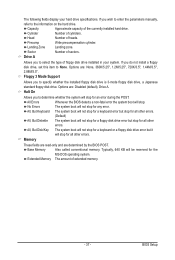
...Sets the system date. Extended IDE Drive Configure your IDE/SATA devices by using one of the two methods below : • Auto Lets the BIOS automatically detect IDE/SATA devices during the POST. (Default) • None If no IDE/SATA devices are used , set this item to None.... Access Mode Sets the hard drive access mode. IDE Channel 2, 3, 4, 5 Master IDE Auto-Detection Press to set the date. For example, 1 p.m. BIOS Setup - 36 - Select the desired field and use the up arrow or down arrow key to autodetect the parameters of the IDE/SATA device on...
...Sets the system date. Extended IDE Drive Configure your IDE/SATA devices by using one of the two methods below : • Auto Lets the BIOS automatically detect IDE/SATA devices during the POST. (Default) • None If no IDE/SATA devices are used , set this item to None.... Access Mode Sets the hard drive access mode. IDE Channel 2, 3, 4, 5 Master IDE Auto-Detection Press to set the date. For example, 1 p.m. BIOS Setup - 36 - Select the desired field and use the up arrow or down arrow key to autodetect the parameters of the IDE/SATA device on...
Manual
Page 37
... - 37 - Head Number of cylinders. Options are : None, 360K/5.25", 1.2M/5.25", 720K/3.5", 1.44M/3.5", 2.88M/3.5". All Errors Whenever the BIOS detects a non-fatal error the system boot will stop for all other errors. All, But Keyboard The system boot will not stop for a keyboard ...(Default) All, But Diskette The system boot will not stop for an error during the POST. Base Memory Also called conventional memory. BIOS Setup The following fields display your system. If you to the information on the hard drive. Floppy 3 Mode Support Allows you wish...
... - 37 - Head Number of cylinders. Options are : None, 360K/5.25", 1.2M/5.25", 720K/3.5", 1.44M/3.5", 2.88M/3.5". All Errors Whenever the BIOS detects a non-fatal error the system boot will stop for all other errors. All, But Keyboard The system boot will not stop for a keyboard ...(Default) All, But Diskette The system boot will not stop for an error during the POST. Base Memory Also called conventional memory. BIOS Setup The following fields display your system. If you to the information on the hard drive. Floppy 3 Mode Support Allows you wish...
Manual
Page 38
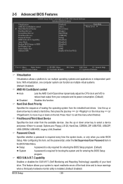
... to issue warnings when a third party hardware monitor utility is required for booting the system and for entering the BIOS Setup program. Capability Enables or disables the S.M.A.R.T. (Self Monitoring and Reporting Technology) capability of the hard drive and...Cool&Quiet control } Hard Disk Boot Priority First Boot Device Second Boot Device Third Boot Device Password Check HDD S.M.A.R.T. Capability Away Mode Backup BIOS Image to HDD Init Display First Frame Buffer Size Onboard GPU [Enabled] [Auto] [Press Enter] [Floppy] [Hard Disk] [CDROM]...
... to issue warnings when a third party hardware monitor utility is required for booting the system and for entering the BIOS Setup program. Capability Enables or disables the S.M.A.R.T. (Self Monitoring and Reporting Technology) capability of the hard drive and...Cool&Quiet control } Hard Disk Boot Priority First Boot Device Second Boot Device Third Boot Device Password Check HDD S.M.A.R.T. Capability Away Mode Backup BIOS Image to HDD Init Display First Frame Buffer Size Onboard GPU [Enabled] [Auto] [Press Enter] [Floppy] [Hard Disk] [CDROM]...


