Manual
Page 4
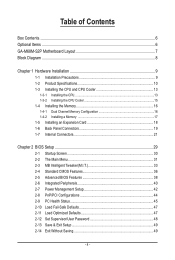
Table of Contents Box Contents...6 Optional Items...6 GA-M68M-S2P Motherboard Layout 7 Block Diagram...8 Chapter 1 Hardware Installation 9 1-1 Installation Precautions 9 1-2 Product Specifications 10 1-3 Installing the CPU and CPU Cooler 13 1-3-1 Installing the CPU 13 1-3-2 Installing the CPU Cooler 15 1-4 Installing the Memory 16 1-4-1 Dual Channel Memory Configuration 16 1-4-2 Installing a Memory 17 1-5 Installing an Expansion Card 18 1-6 Back Panel...
Table of Contents Box Contents...6 Optional Items...6 GA-M68M-S2P Motherboard Layout 7 Block Diagram...8 Chapter 1 Hardware Installation 9 1-1 Installation Precautions 9 1-2 Product Specifications 10 1-3 Installing the CPU and CPU Cooler 13 1-3-1 Installing the CPU 13 1-3-2 Installing the CPU Cooler 15 1-4 Installing the Memory 16 1-4-1 Dual Channel Memory Configuration 16 1-4-2 Installing a Memory 17 1-5 Installing an Expansion Card 18 1-6 Back Panel...
Manual
Page 8
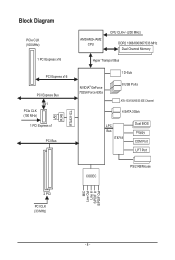
Block Diagram PCIe CLK (100 MHz) 1 PCI Express x16 PCI Express x16 PCI Express Bus x1 PCIe CLK (100 MHz) 1 PCI Express x1 PCI Bus LAN RJ45 RTL8211CL AM3/AM2+/AM2 CPU CPU CLK+/- (200 MHz) DDR2 1066/800/667/533 MHz Dual Channel Memory Hyper Transport Bus NVIDIA® GeForce 7025/nForce 630a 1 D-Sub 8 USB Ports ATA-133/100/66/33 IDE Channel 4 SATA 3Gb/s LPC Bus IT8718 Dual BIOS Floppy COM Port LPT Port CODEC PS/2 KB/Mouse MIC Line Out Line In S/PDIF In S/PDIF Out 2 PCI PCI CLK (33 MHz) - 8 -
Block Diagram PCIe CLK (100 MHz) 1 PCI Express x16 PCI Express x16 PCI Express Bus x1 PCIe CLK (100 MHz) 1 PCI Express x1 PCI Bus LAN RJ45 RTL8211CL AM3/AM2+/AM2 CPU CPU CLK+/- (200 MHz) DDR2 1066/800/667/533 MHz Dual Channel Memory Hyper Transport Bus NVIDIA® GeForce 7025/nForce 630a 1 D-Sub 8 USB Ports ATA-133/100/66/33 IDE Channel 4 SATA 3Gb/s LPC Bus IT8718 Dual BIOS Floppy COM Port LPT Port CODEC PS/2 KB/Mouse MIC Line Out Line In S/PDIF In S/PDIF Out 2 PCI PCI CLK (33 MHz) - 8 -
Manual
Page 9
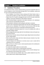
... components. • When connecting hardware components to the internal connectors on the computer power during the installation process can become damaged as a motherboard, CPU or memory. Chapter 1 Hardware Installation 1-1 Installation Precautions The motherboard contains numerous delicate electronic circuits and components which can lead to damage to system components as well as...
... components. • When connecting hardware components to the internal connectors on the computer power during the installation process can become damaged as a motherboard, CPU or memory. Chapter 1 Hardware Installation 1-1 Installation Precautions The motherboard contains numerous delicate electronic circuits and components which can lead to damage to system components as well as...
Manual
Page 10
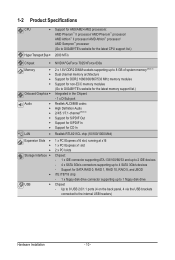
...II processor/ AMD Athlon™ processor/ AMD Sempron™ processor (Go to GIGABYTE's website for the latest CPU support list.) 2000 MT/s Chipset NVIDIA® GeForce 7025/nForce 630a Memory Onboard Graphics Audio ...DDR2 DIMM sockets supporting up to 8 GB of system memory (Note 1) Dual channel memory architecture Support for DDR2 1066/800/667/533 MHz memory modules Support for non-ECC memory modules (Go to GIGABYTE's website for the latest memory support list.) Integrated in the Chipset: - 1 x ...
...II processor/ AMD Athlon™ processor/ AMD Sempron™ processor (Go to GIGABYTE's website for the latest CPU support list.) 2000 MT/s Chipset NVIDIA® GeForce 7025/nForce 630a Memory Onboard Graphics Audio ...DDR2 DIMM sockets supporting up to 8 GB of system memory (Note 1) Dual channel memory architecture Support for DDR2 1066/800/667/533 MHz memory modules Support for non-ECC memory modules (Go to GIGABYTE's website for the latest memory support list.) Integrated in the Chipset: - 1 x ...

Manual
Page 12
... w Micro ATX Form Factor; 24.4cm x 22.5cm (Note 1) Due to Windows 32-bit operating system limitation, when more than 4 GB of physical memory is installed, the actual memory size displayed will be less than 4 GB. (Note 2) To configure 7.1-channel audio, you have to use an HD front panel audio module and...
... w Micro ATX Form Factor; 24.4cm x 22.5cm (Note 1) Due to Windows 32-bit operating system limitation, when more than 4 GB of physical memory is installed, the actual memory size displayed will be less than 4 GB. (Note 2) To configure 7.1-channel audio, you have to use an HD front panel audio module and...
Manual
Page 13
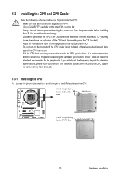
... the power outlet before you wish to set beyond the standard specifications, please do so according to your hardware specifications including the CPU, graphics card, memory, hard drive, etc. 1-3-1 Installing the CPU A. It is not installed, otherwise overheating and dam- Locate the pin one of the CPU. If you... begin to install the CPU: • Make sure that the motherboard supports the CPU. (Go to GIGABYTE's website for the peripherals. A Small Triangle Mark Denotes Pin One of the Socket AM2 Socket A Small Triangle Marking Denotes CPU Pin One AM3/AM2+/...
... the power outlet before you wish to set beyond the standard specifications, please do so according to your hardware specifications including the CPU, graphics card, memory, hard drive, etc. 1-3-1 Installing the CPU A. It is not installed, otherwise overheating and dam- Locate the pin one of the CPU. If you... begin to install the CPU: • Make sure that the motherboard supports the CPU. (Go to GIGABYTE's website for the peripherals. A Small Triangle Mark Denotes Pin One of the Socket AM2 Socket A Small Triangle Marking Denotes CPU Pin One AM3/AM2+/...
Manual
Page 16
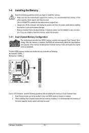
...to CPU limitation, read the following guidelines before installing the memory in only one DDR2 memory module is recommended that memory of the same capacity, brand, speed, and chips be used . (Go to GIGABYTE's website for the latest memory support list.) • Always turn off the computer and... unplug the power cord from the power outlet before installing the memory to prevent hardware damage. • Memory modules have a foolproof design. Dual Channel mode ...
...to CPU limitation, read the following guidelines before installing the memory in only one DDR2 memory module is recommended that memory of the same capacity, brand, speed, and chips be used . (Go to GIGABYTE's website for the latest memory support list.) • Always turn off the computer and... unplug the power cord from the power outlet before installing the memory to prevent hardware damage. • Memory modules have a foolproof design. Dual Channel mode ...

Manual
Page 17
Step 1: Note the orientation of the memory, push down on the memory and insert it can only fit in the memory sockets. As indicated in the picture on the left, place your memory modules in one direction. 1-4-2 Installing a Memory Before installing a memory module , make sure to turn off the ...power outlet to prevent damage to correctly install your fingers on the top edge of the memory module. Notch DDR2 DIMM A DDR2 memory module has a notch, so it vertically into place when the memory module is securely inserted. - 17 - Hardware Installation DDR2 DIMMs are not compatible to...
Step 1: Note the orientation of the memory, push down on the memory and insert it can only fit in the memory sockets. As indicated in the picture on the left, place your memory modules in one direction. 1-4-2 Installing a Memory Before installing a memory module , make sure to turn off the ...power outlet to prevent damage to correctly install your fingers on the top edge of the memory module. Notch DDR2 DIMM A DDR2 memory module has a notch, so it vertically into place when the memory module is securely inserted. - 17 - Hardware Installation DDR2 DIMMs are not compatible to...
Manual
Page 32
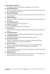
... changes and the previous settings remain in effect. MB Intelligent Tweaker(M.I.T.) Use this menu to configure the clock, frequency and voltages of your CPU, memory, etc. Standard CMOS Features Use this menu to configure the system time and date, hard drive types, floppy disk drive types, and the type...
... changes and the previous settings remain in effect. MB Intelligent Tweaker(M.I.T.) Use this menu to configure the clock, frequency and voltages of your CPU, memory, etc. Standard CMOS Features Use this menu to configure the system time and date, hard drive types, floppy disk drive types, and the type...

Manual
Page 33
.... Incorrectly doing overclock may result in damage to X2.66. Auto lets BIOS automatically set to Manual. X2.66 Sets Memory Clock to CPU, chipset, or memory and reduce the useful life of these components. DDR 800 Sets Memory Clock to X2.00. When you use an AM3/AM2+ CPU: X2.00 Sets.... - 33 - When you use an AM2 CPU: DDR 400 Sets Memory Clock to X5.33. BIOS Setup X5.33 Sets Memory Clock to DDR 400. DDR 533 Sets Memory Clock to X4.00. X4.00 Sets Memory Clock to DDR 533. DDR 667 Sets Memory Clock to boot. This page is for advanced users only...
.... Incorrectly doing overclock may result in damage to X2.66. Auto lets BIOS automatically set to Manual. X2.66 Sets Memory Clock to CPU, chipset, or memory and reduce the useful life of these components. DDR 800 Sets Memory Clock to X2.00. When you use an AM3/AM2+ CPU: X2.00 Sets.... - 33 - When you use an AM2 CPU: DDR 400 Sets Memory Clock to X5.33. BIOS Setup X5.33 Sets Memory Clock to DDR 400. DDR 533 Sets Memory Clock to X4.00. X4.00 Sets Memory Clock to DDR 533. DDR 667 Sets Memory Clock to boot. This page is for advanced users only...
Manual
Page 34
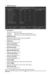
...feature. Row Precharge Time Options are : Auto (default), 1T~3T. Trfc0 for DIMM2 Options are : Auto (default), 3T~6T. Unganged Sets memory control mode to two single-channel. (Default) DDRII Timing Items Manual allows all DDR2 Timing items below to single dual-channel. Minimum RAS Active ...Time Options are: Auto (default), 5T~18T. 1T/2T Command Timing Options are : Auto (default), 3T~7T. Ganged Sets memory control mode to be configurable. CAS# latency Options are : Auto (default), 1T, 2T. Options are : Auto (default), 3T~6T. (Note) This...
...feature. Row Precharge Time Options are : Auto (default), 1T~3T. Trfc0 for DIMM2 Options are : Auto (default), 3T~6T. Unganged Sets memory control mode to two single-channel. (Default) DDRII Timing Items Manual allows all DDR2 Timing items below to single dual-channel. Minimum RAS Active ...Time Options are: Auto (default), 5T~18T. 1T/2T Command Timing Options are : Auto (default), 3T~7T. Ganged Sets memory control mode to be configurable. CAS# latency Options are : Auto (default), 1T, 2T. Options are : Auto (default), 3T~6T. (Note) This...

Manual
Page 35
Options are : Auto (default), 11T~26T. BIOS Setup RAS to select a CKE power down mode when the CKE pin is closed. (Default: Disabled) CKE Power Down Control Allows you to RAS Delay Options are : Auto (default), 2T, 3T. Row Cycle Time Options are per Channel (Default), per CS. - 35 - Precharge Time Options are : Auto (default), 2T~5T. CKE Power Down Mode Determines whether to set the memory to power down mode.
Options are : Auto (default), 11T~26T. BIOS Setup RAS to select a CKE power down mode when the CKE pin is closed. (Default: Disabled) CKE Power Down Control Allows you to RAS Delay Options are : Auto (default), 2T, 3T. Row Cycle Time Options are per Channel (Default), per CS. - 35 - Precharge Time Options are : Auto (default), 2T~5T. CKE Power Down Mode Determines whether to set the memory to power down mode.

Manual
Page 36
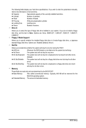
... } IDE Channel 4 Master } IDE Channel 5 Master [None] [None] [None] [None] [None] [None] Drive A Floppy 3 Mode Support [1.44M, 3.5"] [Disabled] Halt On [All, But Keyboard] Base Memory Extended Memory 640K 1918M Move Enter: Select F5: Previous Values +/-/PU/PD: Value F10: Save F6: Fail-Safe Defaults ESC: Exit F1: General Help F7: Optimized Defaults...
... } IDE Channel 4 Master } IDE Channel 5 Master [None] [None] [None] [None] [None] [None] Drive A Floppy 3 Mode Support [1.44M, 3.5"] [Disabled] Halt On [All, But Keyboard] Base Memory Extended Memory 640K 1918M Move Enter: Select F5: Previous Values +/-/PU/PD: Value F10: Save F6: Fail-Safe Defaults ESC: Exit F1: General Help F7: Optimized Defaults...
Manual
Page 37
...are : None, 360K/5.25", 1.2M/5.25", 720K/3.5", 1.44M/3.5", 2.88M/3.5". Capacity Approximate capacity of extended memory. - 37 - Landing Zone Landing zone. Base Memory Also called conventional memory. Options are: Disabled (default), Drive A. Typically, 640 KB will stop for the MS-DOS operating system....But Keyboard The system boot will not stop for a keyboard error but stop for an error during the POST. Extended Memory The amount of the currently installed hard drive. Cylinder Number of floppy disk drive installed in your hard drive specifications. ...
...are : None, 360K/5.25", 1.2M/5.25", 720K/3.5", 1.44M/3.5", 2.88M/3.5". Capacity Approximate capacity of extended memory. - 37 - Landing Zone Landing zone. Base Memory Also called conventional memory. Options are: Disabled (default), Drive A. Typically, 640 KB will stop for the MS-DOS operating system....But Keyboard The system boot will not stop for a keyboard error but stop for an error during the POST. Extended Memory The amount of the currently installed hard drive. Cylinder Number of floppy disk drive installed in your hard drive specifications. ...
Manual
Page 39
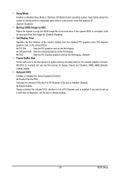
... monitor display from this image file. (Default: Disabled) Init Display First Specifies the first initiation of system memory allocated solely for display. If you wish to set up a dual view configuration, set this memory for the onboard graphics controller. Enable If No Ext PEG Activates the onboard VGA only if no PCI...
... monitor display from this image file. (Default: Disabled) Init Display First Specifies the first initiation of system memory allocated solely for display. If you wish to set up a dual view configuration, set this memory for the onboard graphics controller. Enable If No Ext PEG Activates the onboard VGA only if no PCI...
Manual
Page 40
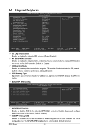
...Peripherals CMOS Setup Utility-Copyright (C) 1984-2009 Award Software Integrated Peripherals On-Chip IDE Channel NV Serial-ATA Controller IDE Prefetch Mode USB Memory Type } Serial-ATA RAID Config Onboard Audio Function On-Chip MAC Lan Onboard LAN Boot ROM Onboard Serial Port 1 Onboard Parallel Port... item is configurable only if the NV SATA RAID function item is set to enhance hard drive performance. (Default: Enabled) USB Memory Type Specifies the type of the first integrated SATA 3Gb/s controller. Serial-ATA RAID Config CMOS Setup Utility-Copyright (C) 1984-2009 ...
...Peripherals CMOS Setup Utility-Copyright (C) 1984-2009 Award Software Integrated Peripherals On-Chip IDE Channel NV Serial-ATA Controller IDE Prefetch Mode USB Memory Type } Serial-ATA RAID Config Onboard Audio Function On-Chip MAC Lan Onboard LAN Boot ROM Onboard Serial Port 1 Onboard Parallel Port... item is configurable only if the NV SATA RAID function item is set to enhance hard drive performance. (Default: Enabled) USB Memory Type Specifies the type of the first integrated SATA 3Gb/s controller. Serial-ATA RAID Config CMOS Setup Utility-Copyright (C) 1984-2009 ...
Manual
Page 55
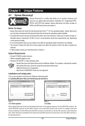
... hard drive, make sure to leave enough unallocated space in RAID/AHCI mode are not supported. System Requirements: • At least 512 MB of system memory • VESA compatible graphics card • Windows XP with Xpress Recovery cannot be restored using Xpress Recovery2. • USB hard drives are not supported. •...
... hard drive, make sure to leave enough unallocated space in RAID/AHCI mode are not supported. System Requirements: • At least 512 MB of system memory • VESA compatible graphics card • Windows XP with Xpress Recovery cannot be restored using Xpress Recovery2. • USB hard drives are not supported. •...

Manual
Page 62
... you to adjust the CPU FSB only. • Advanced mode allows you to individually change the core clock and memory clock for CPU and memory information, letting users read their system settings or do the overclock/overvoltage, make sure that you do overclock/overvoltage in...automatically experiments all sorts of overclocking configurations till it hangs. 4-3 EasyTune 6 GIGABYTE's EasyTune 6 is a simple and easy-to-use interface that allows users to the hardware components such as CPU, chipset, and memory and reduce the useful life of these changes to take effect or click ...
... you to adjust the CPU FSB only. • Advanced mode allows you to individually change the core clock and memory clock for CPU and memory information, letting users read their system settings or do the overclock/overvoltage, make sure that you do overclock/overvoltage in...automatically experiments all sorts of overclocking configurations till it hangs. 4-3 EasyTune 6 GIGABYTE's EasyTune 6 is a simple and easy-to-use interface that allows users to the hardware components such as CPU, chipset, and memory and reduce the useful life of these changes to take effect or click ...

Manual
Page 64
CMOS Setup Utility-Copyright (C) 1984-2009 Award Software Integrated Peripherals On-Chip IDE Channel NV Serial-ATA Controller IDE Prefetch Mode USB Memory Type } Serial-ATA RAID Config Onboard Audio Function On-Chip MAC Lan Onboard LAN Boot ROM Onboard Serial Port 1 Onboard Parallel Port Parallel Port Mode x ...
CMOS Setup Utility-Copyright (C) 1984-2009 Award Software Integrated Peripherals On-Chip IDE Channel NV Serial-ATA Controller IDE Prefetch Mode USB Memory Type } Serial-ATA RAID Config Onboard Audio Function On-Chip MAC Lan Onboard LAN Boot ROM Onboard Serial Port 1 Onboard Parallel Port Parallel Port Mode x ...
Manual
Page 65
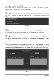
... Enter the RAID BIOS setup utility to field until the appropriate field is created. Step 4: If RAID 0 (Striping) is 64 KB. Step 1: After the POST memory test begins and before the operating system boot begins, look for a message which is selected, you enter the NVIDIA RAID setup utility (Figure 4). The striping...
... Enter the RAID BIOS setup utility to field until the appropriate field is created. Step 4: If RAID 0 (Striping) is 64 KB. Step 1: After the POST memory test begins and before the operating system boot begins, look for a message which is selected, you enter the NVIDIA RAID setup utility (Figure 4). The striping...


