Manual
Page 4
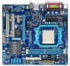
Table of Contents Box Contents...6 Optional Items...6 GA-M68M-S2P Motherboard Layout 7 Block Diagram...8 Chapter 1 Hardware Installation 9 1-1 Installation Precautions 9 1-2 Product Specifications 10 1-3 Installing the CPU and CPU Cooler 13 1-3-1 Installing the CPU 13 1-3-2 Installing the CPU Cooler 15 1-4 Installing the Memory 16 1-4-1 Dual Channel Memory Configuration 16 1-4-2 Installing a Memory 17 1-5 Installing an Expansion Card 18 1-6 Back Panel Connectors...
Table of Contents Box Contents...6 Optional Items...6 GA-M68M-S2P Motherboard Layout 7 Block Diagram...8 Chapter 1 Hardware Installation 9 1-1 Installation Precautions 9 1-2 Product Specifications 10 1-3 Installing the CPU and CPU Cooler 13 1-3-1 Installing the CPU 13 1-3-2 Installing the CPU Cooler 15 1-4 Installing the Memory 16 1-4-1 Dual Channel Memory Configuration 16 1-4-2 Installing a Memory 17 1-5 Installing an Expansion Card 18 1-6 Back Panel Connectors...
Manual
Page 8
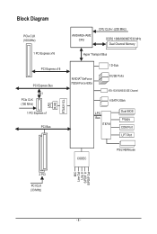
Block Diagram PCIe CLK (100 MHz) 1 PCI Express x16 PCI Express x16 PCI Express Bus x1 PCIe CLK (100 MHz) 1 PCI Express x1 PCI Bus LAN RJ45 RTL8211CL AM3/AM2+/AM2 CPU CPU CLK+/- (200 MHz) DDR2 1066/800/667/533 MHz Dual Channel Memory Hyper Transport Bus NVIDIA® GeForce 7025/nForce 630a 1 D-Sub 8 USB Ports ATA-133/100/66/33 IDE Channel 4 SATA 3Gb/s LPC Bus IT8718 Dual BIOS Floppy COM Port LPT Port CODEC PS/2 KB/Mouse MIC Line Out Line In S/PDIF In S/PDIF Out 2 PCI PCI CLK (33 MHz) - 8 -
Block Diagram PCIe CLK (100 MHz) 1 PCI Express x16 PCI Express x16 PCI Express Bus x1 PCIe CLK (100 MHz) 1 PCI Express x1 PCI Bus LAN RJ45 RTL8211CL AM3/AM2+/AM2 CPU CPU CLK+/- (200 MHz) DDR2 1066/800/667/533 MHz Dual Channel Memory Hyper Transport Bus NVIDIA® GeForce 7025/nForce 630a 1 D-Sub 8 USB Ports ATA-133/100/66/33 IDE Channel 4 SATA 3Gb/s LPC Bus IT8718 Dual BIOS Floppy COM Port LPT Port CODEC PS/2 KB/Mouse MIC Line Out Line In S/PDIF In S/PDIF Out 2 PCI PCI CLK (33 MHz) - 8 -
Manual
Page 9
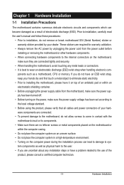
... 1 Hardware Installation 1-1 Installation Precautions The motherboard contains numerous delicate electronic circuits and components which can lead to damage to system components as well as a motherboard, CPU or memory.
... 1 Hardware Installation 1-1 Installation Precautions The motherboard contains numerous delicate electronic circuits and components which can lead to damage to system components as well as a motherboard, CPU or memory.
Manual
Page 10
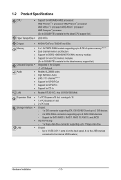
.../ AMD Phenom™ processor/ AMD Athlon™ II processor/ AMD Athlon™ processor/ AMD Sempron™ processor (Go to GIGABYTE's website for the latest CPU support list.) 2000 MT/s Chipset NVIDIA® GeForce 7025/nForce 630a Memory Onboard Graphics Audio ...1) Dual channel memory architecture Support for DDR2 1066/800/667/533 MHz memory modules Support for non-ECC memory modules (Go to GIGABYTE's website for the latest memory support list.) Integrated in the Chipset: - 1 x D-Sub port Realtek ALC888B codec High Definition Audio...
.../ AMD Phenom™ processor/ AMD Athlon™ II processor/ AMD Athlon™ processor/ AMD Sempron™ processor (Go to GIGABYTE's website for the latest CPU support list.) 2000 MT/s Chipset NVIDIA® GeForce 7025/nForce 630a Memory Onboard Graphics Audio ...1) Dual channel memory architecture Support for DDR2 1066/800/667/533 MHz memory modules Support for non-ECC memory modules (Go to GIGABYTE's website for the latest memory support list.) Integrated in the Chipset: - 1 x D-Sub port Realtek ALC888B codec High Definition Audio...

Manual
Page 11
...ATX main power connector w 1 x 4-pin ATX 12V power connector w 1 x floppy disk drive connector w 1 x IDE connector w 4 x SATA 3Gb/s connectors w 1 x CPU fan header w 1 x system fan header w 1 x front panel header w 1 x front panel audio header w 1 x CD In connector w 1 x S/PDIF In/Out... Monitor w w w w w w BIOS w w w w System voltage detection CPU/System temperature detection CPU/System fan speed detection CPU/System overheating warning CPU/System fan fail warning CPU fan speed control (Note 3) 2 x 8 Mbit flash Use of licensed AWARD BIOS...
...ATX main power connector w 1 x 4-pin ATX 12V power connector w 1 x floppy disk drive connector w 1 x IDE connector w 4 x SATA 3Gb/s connectors w 1 x CPU fan header w 1 x system fan header w 1 x front panel header w 1 x front panel audio header w 1 x CD In connector w 1 x S/PDIF In/Out... Monitor w w w w w w BIOS w w w w System voltage detection CPU/System temperature detection CPU/System fan speed detection CPU/System overheating warning CPU/System fan fail warning CPU fan speed control (Note 3) 2 x 8 Mbit flash Use of licensed AWARD BIOS...

Manual
Page 12
..., you have to use an HD front panel audio module and enable the multi-channel audio feature through the audio driver. (Note 3) Whether the CPU fan speed control function is supported will depend on the CPU cooler you install. (Note 4) Available functions in EasyTune may differ by motherboard model. Hardware Installation - 12 -
..., you have to use an HD front panel audio module and enable the multi-channel audio feature through the audio driver. (Note 3) Whether the CPU fan speed control function is supported will depend on the CPU cooler you install. (Note 4) Available functions in EasyTune may differ by motherboard model. Hardware Installation - 12 -
Manual
Page 13
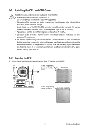
... inserted if oriented incorrectly. (Or you begin to install the CPU: • Make sure that the motherboard supports the CPU. (Go to GIGABYTE's website for the peripherals. Locate the pin one of the CPU. 1-3 Installing the CPU and CPU Cooler Read the following guidelines before installing the CPU to prevent hardware damage. • Locate the pin one...
... inserted if oriented incorrectly. (Or you begin to install the CPU: • Make sure that the motherboard supports the CPU. (Go to GIGABYTE's website for the peripherals. Locate the pin one of the CPU. 1-3 Installing the CPU and CPU Cooler Read the following guidelines before installing the CPU to prevent hardware damage. • Locate the pin one...
Manual
Page 14
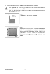
... the power outlet to prevent damage to the CPU. • Do not force the CPU into their holes. Make sure that the CPU pins fit perfectly into the CPU socket. CPU Socket Locking Lever Step 1: Completely lift up the CPU socket locking lever. Hardware Installation - 14 - Once the CPU is positioned into its socket, place one (small...
... the power outlet to prevent damage to the CPU. • Do not force the CPU into their holes. Make sure that the CPU pins fit perfectly into the CPU socket. CPU Socket Locking Lever Step 1: Completely lift up the CPU socket locking lever. Hardware Installation - 14 - Once the CPU is positioned into its socket, place one (small...
Manual
Page 15
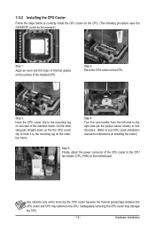
... the example.) Step 1: Apply an even and thin layer of thermal grease on the surface of the installed CPU. 1-3-2 Installing the CPU Cooler Follow the steps below to correctly install the CPU cooler on the CPU. (The following procedure uses the GIGABYTE cooler as the picture above shows) to lock into place. (Refer to your...
... the example.) Step 1: Apply an even and thin layer of thermal grease on the surface of the installed CPU. 1-3-2 Installing the CPU Cooler Follow the steps below to correctly install the CPU cooler on the CPU. (The following procedure uses the GIGABYTE cooler as the picture above shows) to lock into place. (Refer to your...
Manual
Page 16
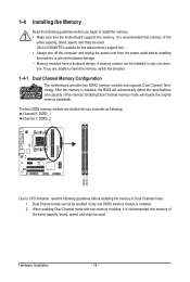
... mode will automatically detect the specifications and capacity of the same capacity, brand, speed, and chips be used . (Go to GIGABYTE's website for the latest memory support list.) • Always turn off the computer and unplug the power cord from the power outlet... Hardware Installation - 16 - If you are divided into two channels as following: Channel 0: DDR2_1 Channel 1: DDR2_2 DDR2_1 DDR2_2 Due to CPU limitation, read the following guidelines before you begin to insert the memory, switch the direction. 1-4-1 Dual Channel Memory Configuration This motherboard provides ...
... mode will automatically detect the specifications and capacity of the same capacity, brand, speed, and chips be used . (Go to GIGABYTE's website for the latest memory support list.) • Always turn off the computer and unplug the power cord from the power outlet... Hardware Installation - 16 - If you are divided into two channels as following: Channel 0: DDR2_1 Channel 1: DDR2_2 DDR2_1 DDR2_2 Due to CPU limitation, read the following guidelines before you begin to insert the memory, switch the direction. 1-4-1 Dual Channel Memory Configuration This motherboard provides ...
Manual
Page 22
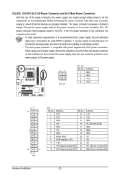
... recommended that a power supply that can withstand high power consumption be used that does not provide the required power, the result can lead to the CPU.
... recommended that a power supply that can withstand high power consumption be used that does not provide the required power, the result can lead to the CPU.
Manual
Page 23
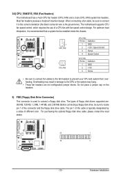
... speed control, which requires the use of different color. Overheating may result in the correct orientation (the black connector wire is used to the CPU or the system may hang. • These fan headers are : 360 KB, 720 KB, 1.2 MB, 1.44 MB, and 2.88 MB. The pin ... disk drive cable. Most fan headers possess a foolproof insertion design. When connecting a fan cable, be sure to connect it is typically designated by a stripe of a CPU fan with fan speed control design. Definition 1 GND 2 +12V / Speed Control 3 Sense 4 Speed Control SYS_FAN: Pin No. 1 2 3 Definition GND +12V Sense •...
... speed control, which requires the use of different color. Overheating may result in the correct orientation (the black connector wire is used to the CPU or the system may hang. • These fan headers are : 360 KB, 720 KB, 1.2 MB, 1.44 MB, and 2.88 MB. The pin ... disk drive cable. Most fan headers possess a foolproof insertion design. When connecting a fan cable, be sure to connect it is typically designated by a stripe of a CPU fan with fan speed control design. Definition 1 GND 2 +12V / Speed Control 3 Sense 4 Speed Control SYS_FAN: Pin No. 1 2 3 Definition GND +12V Sense •...

Manual
Page 31
... Fail-Safe Defaults Load Optimized Defaults Set Supervisor Password Set User Password Save & Exit Setup Exit Without Saving Select Item F10: Save & Exit Setup Change CPU's Clock & Voltage BIOS Setup Program Function Keys Move the selection bar to select an item Execute command or enter the submenu Main Menu: Exit the...
... Fail-Safe Defaults Load Optimized Defaults Set Supervisor Password Set User Password Save & Exit Setup Exit Without Saving Select Item F10: Save & Exit Setup Change CPU's Clock & Voltage BIOS Setup Program Function Keys Move the selection bar to select an item Execute command or enter the submenu Main Menu: Exit the...
Manual
Page 32
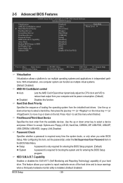
...that stop the system boot, etc. Advanced BIOS Features Use this menu to configure the device boot order, advanced features available on the CPU, and the primary display adapter. Integrated Peripherals Use this menu to configure all peripheral devices, such as IDE, SATA, USB, integrated...Use this menu to configure the system's PCI & PnP resources. PC Health Status Use this menu to see information about autodetected system/CPU temperature, system voltage and fan speed, etc. Load Fail-Safe Defaults Fail-Safe defaults are factory settings for the most stable, ...
...that stop the system boot, etc. Advanced BIOS Features Use this menu to configure the device boot order, advanced features available on the CPU, and the primary display adapter. Integrated Peripherals Use this menu to configure all peripheral devices, such as IDE, SATA, USB, integrated...Use this menu to configure the system's PCI & PnP resources. PC Health Status Use this menu to see information about autodetected system/CPU temperature, system voltage and fan speed, etc. Load Fail-Safe Defaults Fail-Safe defaults are factory settings for the most stable, ...

Manual
Page 33
... not to alter the default settings to prevent system instability or other unexpected results. (Inadequately altering the settings may result in system's failure to CPU, chipset, or memory and reduce the useful life of these components. BIOS Setup Auto lets BIOS automatically set the memory clock. Manual allows the...Safe Defaults ESC: Exit F1: General Help F7: Optimized Defaults Whether the system will work stably with the overclock settings you use an AM2 CPU: DDR 400 Sets Memory Clock to DDR 533. When you made is for advanced users only and we recommend you use an AM3/AM2...
... not to alter the default settings to prevent system instability or other unexpected results. (Inadequately altering the settings may result in system's failure to CPU, chipset, or memory and reduce the useful life of these components. BIOS Setup Auto lets BIOS automatically set the memory clock. Manual allows the...Safe Defaults ESC: Exit F1: General Help F7: Optimized Defaults Whether the system will work stably with the overclock settings you use an AM2 CPU: DDR 400 Sets Memory Clock to DDR 533. When you made is for advanced users only and we recommend you use an AM3/AM2...
Manual
Page 34
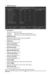
...: Previous Values +/-/PU/PD: Value F10: Save F6: Fail-Safe Defaults ESC: Exit F1: General Help F7: Optimized Defaults DCTs Mode (Note) Allows you install a CPU that supports this feature. Unganged Sets memory control mode to two single-channel. (Default) DDRII Timing Items Manual allows all DDR2 Timing items below to...
...: Previous Values +/-/PU/PD: Value F10: Save F6: Fail-Safe Defaults ESC: Exit F1: General Help F7: Optimized Defaults DCTs Mode (Note) Allows you install a CPU that supports this feature. Unganged Sets memory control mode to two single-channel. (Default) DDRII Timing Items Manual allows all DDR2 Timing items below to...
Manual
Page 38
... computer system can function as multiple virtual systems. (Default: Disabled) AMD K8 Cool&Quiet control Auto Lets the AMD Cool'n'Quiet driver dynamically adjust the CPU clock and VID to move it up or down on the list. Password Check Specifies whether a password is required for booting the system and for...
... computer system can function as multiple virtual systems. (Default: Disabled) AMD K8 Cool&Quiet control Auto Lets the AMD Cool'n'Quiet driver dynamically adjust the CPU clock and VID to move it up or down on the list. Password Check Specifies whether a password is required for booting the system and for...

Manual
Page 45
...of the chassis intrusion detection device attached to the CPU temperature. Enabled clears the record of previous chassis intrusion status. Current System/CPU Temperature Displays current system/CPU temperature. If disabled, the CPU fan runs at full speed. (Default: Enabled)...+3.3V +12V Current System Temperature Current CPU Temperature Current CPU FAN Speed Current SYSTEM FAN Speed System Warning Temperature CPU Warning Temperature CPU FAN Fail Warning SYSTEM FAN Fail Warning CPU Smart FAN Control CPU Smart FAN Mode [Disabled] No 1.364V...
...of the chassis intrusion detection device attached to the CPU temperature. Enabled clears the record of previous chassis intrusion status. Current System/CPU Temperature Displays current system/CPU temperature. If disabled, the CPU fan runs at full speed. (Default: Enabled)...+3.3V +12V Current System Temperature Current CPU Temperature Current CPU FAN Speed Current SYSTEM FAN Speed System Warning Temperature CPU Warning Temperature CPU FAN Fail Warning SYSTEM FAN Fail Warning CPU Smart FAN Control CPU Smart FAN Mode [Disabled] No 1.364V...

Manual
Page 46
Auto Lets the BIOS automatically detect the type of CPU fan installed and sets the optimal CPU fan control mode. (Default) Voltage Sets Voltage mode for a 4-pin CPU fan. BIOS Setup - 46 - CPU Smart FAN Mode Specifies how to Enabled. PWM Sets PWM mode for a 3-pin CPU fan. This item is configurable only if CPU Smart FAN Control is set to control CPU fan speed.
Auto Lets the BIOS automatically detect the type of CPU fan installed and sets the optimal CPU fan control mode. (Default) Voltage Sets Voltage mode for a 4-pin CPU fan. BIOS Setup - 46 - CPU Smart FAN Mode Specifies how to Enabled. PWM Sets PWM mode for a 3-pin CPU fan. This item is configurable only if CPU Smart FAN Control is set to control CPU fan speed.

Manual
Page 62
... and fan speed and set . Incorrectly doing overclock/overvoltage may differ by motherboard model. Unique Features - 62 - 4-3 EasyTune 6 GIGABYTE's EasyTune 6 is a simple and easy-to-use interface that allows users to fine-tune their system-related information without the need to... the system will operate with the optimum overclocking configuration after restart. The user-friendly EasyTune 6 interface also includes tabbed pages for CPU and memory information, letting users read their system settings or do the overclock/overvoltage, make sure that you to a new profile ...
... and fan speed and set . Incorrectly doing overclock/overvoltage may differ by motherboard model. Unique Features - 62 - 4-3 EasyTune 6 GIGABYTE's EasyTune 6 is a simple and easy-to-use interface that allows users to fine-tune their system-related information without the need to... the system will operate with the optimum overclocking configuration after restart. The user-friendly EasyTune 6 interface also includes tabbed pages for CPU and memory information, letting users read their system settings or do the overclock/overvoltage, make sure that you to a new profile ...


