Manual
Page 1
GA-M61PME-S2P AM2+/AM2 socket motherboard for AMD PhenomTM FX processor/AMD PhenomTM X4 processor/ AMD PhenomTM X3 processor/AMD AthlonTM X2 processor/ AMD AthlonTM processor/AMD SempronTM X2 processor/ AMD SempronTM processor User's Manual Rev. 1002 12ME-M61PMEP2-1002R
GA-M61PME-S2P AM2+/AM2 socket motherboard for AMD PhenomTM FX processor/AMD PhenomTM X4 processor/ AMD PhenomTM X3 processor/AMD AthlonTM X2 processor/ AMD AthlonTM processor/AMD SempronTM X2 processor/ AMD SempronTM processor User's Manual Rev. 1002 12ME-M61PMEP2-1002R
Manual
Page 3
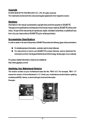
... registered to use of this : "REV: X.X." Check your motherboard looks like this product, GIGABYTE provides the following types of GIGABYTE. Example: - 3 - Disclaimer Information in this manual may be reproduced, copied, translated, transmitted, or published in this manual is protected by GIGABYTE without GIGABYTE's prior written permission. For product-related information, check on our website at: http...
... registered to use of this : "REV: X.X." Check your motherboard looks like this product, GIGABYTE provides the following types of GIGABYTE. Example: - 3 - Disclaimer Information in this manual may be reproduced, copied, translated, transmitted, or published in this manual is protected by GIGABYTE without GIGABYTE's prior written permission. For product-related information, check on our website at: http...
Manual
Page 5
Chapter 3 Drivers Installation 51 3-1 Installing Chipset Drivers 51 3-2 Application Software 52 3-3 Technical Manuals 52 3-4 Contact ...53 3-5 System ...53 3-6 Download Center 54 Chapter 4 Unique Features 55 4-1 Xpress Recovery2 55 4-2 BIOS Update Utilities 58 4-2-1 Updating the BIOS with the Q-Flash ...
Chapter 3 Drivers Installation 51 3-1 Installing Chipset Drivers 51 3-2 Application Software 52 3-3 Technical Manuals 52 3-4 Contact ...53 3-5 System ...53 3-6 Download Center 54 Chapter 4 Unique Features 55 4-1 Xpress Recovery2 55 4-2 BIOS Update Utilities 58 4-2-1 Updating the BIOS with the Q-Flash ...
Manual
Page 6
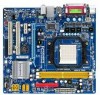
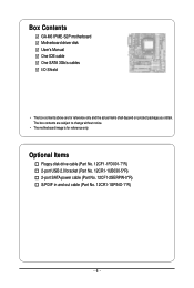
The box contents are for reference only. Optional Items Floppy disk drive cable (Part No. 12CF1-1FD001-7*R) 2-port USB 2.0 bracket (Part No. 12CR1-1UB030-5*R) 2-port SATA power cable (Part No. 12CF1-2SERPW-0*R) S/PDIF in and out cable (Part No. 12CR1-1SPINO-1*R) - 6 - Box Contents GA-M61PME-S2P motherboard Motherboard driver disk User's Manual One IDE cable One SATA 3Gb/s cables I/O Shield • The box contents above are subject to change without notice. • The motherboard image is for reference only and the actual items shall depend on product package you obtain.
The box contents are for reference only. Optional Items Floppy disk drive cable (Part No. 12CF1-1FD001-7*R) 2-port USB 2.0 bracket (Part No. 12CR1-1UB030-5*R) 2-port SATA power cable (Part No. 12CF1-2SERPW-0*R) S/PDIF in and out cable (Part No. 12CR1-1SPINO-1*R) - 6 - Box Contents GA-M61PME-S2P motherboard Motherboard driver disk User's Manual One IDE cable One SATA 3Gb/s cables I/O Shield • The box contents above are subject to change without notice. • The motherboard image is for reference only and the actual items shall depend on product package you obtain.
Manual
Page 9
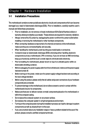
Prior to installation, carefully read the user's manual and follow these procedures: • Prior to installation, do not remove or break motherboard S/N (Serial Number) sticker or warranty sticker provided by unplugging the power ...
Prior to installation, carefully read the user's manual and follow these procedures: • Prior to installation, do not remove or break motherboard S/N (Serial Number) sticker or warranty sticker provided by unplugging the power ...
Manual
Page 14
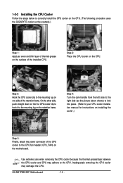
... mounting lug on the retention frame. On the other side, push straight down on the the CPU cooler clip to hook it to the CPU. GA-M61PME-S2P Motherboard - 14 - Step 3: Hook the CPU cooler clip to the CPU fan header (CPU_FAN) on the motherboard. Step 4: Turn the cam handle from ...the steps below to correctly install the CPU cooler on the CPU. (The following procedure uses the GIGABYTE cooler as the picture above shows) to lock into place. (Refer to your CPU cooler installation manual for instructions on installing the cooler.) Step 5: Finally, attach the power connector of the CPU cooler...
... mounting lug on the retention frame. On the other side, push straight down on the the CPU cooler clip to hook it to the CPU. GA-M61PME-S2P Motherboard - 14 - Step 3: Hook the CPU cooler clip to the CPU fan header (CPU_FAN) on the motherboard. Step 4: Turn the cam handle from ...the steps below to correctly install the CPU cooler on the CPU. (The following procedure uses the GIGABYTE cooler as the picture above shows) to lock into place. (Refer to your CPU cooler installation manual for instructions on installing the cooler.) Step 5: Finally, attach the power connector of the CPU cooler...
Manual
Page 17
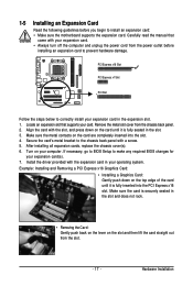
... Card: Gently push back on the lever on the top edge of the card until it is fully inserted into the slot. 4. Carefully read the manual that supports your operating system. After installing all expansion cards, replace the chassis cover(s). 6. PCI Express x16 Slot PCI Express x1 Slot PCI Slot Follow...
... Card: Gently push back on the lever on the top edge of the card until it is fully inserted into the slot. 4. Carefully read the manual that supports your operating system. After installing all expansion cards, replace the chassis cover(s). 6. PCI Express x16 Slot PCI Express x1 Slot PCI Slot Follow...
Manual
Page 29
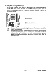
... do so may cause damage to the motherboard. • After system restart, go to BIOS Setup to load factory defaults (select Load Optimized Defaults) or manually configure the BIOS settings (refer to factory defaults. Hardware Installation date information and BIOS configurations) and reset the CMOS values to Chapter 2, "BIOS Setup," for...
... do so may cause damage to the motherboard. • After system restart, go to BIOS Setup to load factory defaults (select Load Optimized Defaults) or manually configure the BIOS settings (refer to factory defaults. Hardware Installation date information and BIOS configurations) and reset the CMOS values to Chapter 2, "BIOS Setup," for...
Manual
Page 35
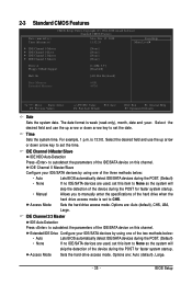
Select the desired field and use the up arrow or down arrow key to manually enter the specifications of the device during the POST for faster system startup. IDE Channel 0 Master/Slave IDE HDD Auto-Detection Press to set this ... Default ESC: Exit F1: General Help F7: Optimized Defaults Date Sets the system date. Allows you to set to None so the system will • Manual skip the detection of the IDE/SATA device on this channel. is 13:0:0. Access Mode Sets the hard drive access mode. Select the desired field...
Select the desired field and use the up arrow or down arrow key to manually enter the specifications of the device during the POST for faster system startup. IDE Channel 0 Master/Slave IDE HDD Auto-Detection Press to set this ... Default ESC: Exit F1: General Help F7: Optimized Defaults Date Sets the system date. Allows you to set to None so the system will • Manual skip the detection of the IDE/SATA device on this channel. is 13:0:0. Access Mode Sets the hard drive access mode. Select the desired field...
Manual
Page 36
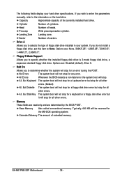
... Also called conventional memory. Extended Memory The amount of the currently installed hard drive. If you wish to enter the parameters manually, refer to None. Head Number of cylinders. Drive A Allows you to specify whether the installed floppy disk drive is 3-... you do not install a floppy disk drive, set this item to the information on the hard drive. Precomp Write precompensation cylinder. GA-M61PME-S2P Motherboard - 36 - Sector Number of floppy disk drive installed in your hard drive specifications. Typically, 640 KB will stop for all...
... Also called conventional memory. Extended Memory The amount of the currently installed hard drive. If you wish to enter the parameters manually, refer to None. Head Number of cylinders. Drive A Allows you to specify whether the installed floppy disk drive is 3-... you do not install a floppy disk drive, set this item to the information on the hard drive. Precomp Write precompensation cylinder. GA-M61PME-S2P Motherboard - 36 - Sector Number of floppy disk drive installed in your hard drive specifications. Typically, 640 KB will stop for all...

Manual
Page 51
... recommended to install. • Please ignore the popup dialog box(es) (e.g. The driver Autorun screen is installing the drivers. Or click Install Single Items to manually select the drivers you wish to install. You can click the Install All button and "Xpress Install" will install all the drivers that shown in...
... recommended to install. • Please ignore the popup dialog box(es) (e.g. The driver Autorun screen is installing the drivers. Or click Install Single Items to manually select the drivers you wish to install. You can click the Install All button and "Xpress Install" will install all the drivers that shown in...
Manual
Page 52
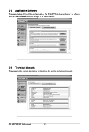
You can click the Install button on the right of an item to install it. 3-3 Technical Manuals This page provides content descriptions for this driver disk and the motherboard manuals. GA-M61PME-S2P Motherboard - 52 - 3-2 Application Software This page displays all the utilities and applications that GIGABYTE develops and some free software.
You can click the Install button on the right of an item to install it. 3-3 Technical Manuals This page provides content descriptions for this driver disk and the motherboard manuals. GA-M61PME-S2P Motherboard - 52 - 3-2 Application Software This page displays all the utilities and applications that GIGABYTE develops and some free software.
Manual
Page 58
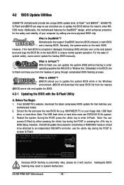
... or a hard drive attached to an independent IDE/SATA controller, use FAT32/16/12 file system. 3. 4-2 BIOS Update Utilities GIGABYTE motherboards provide two unique BIOS update tools, Q-FlashTM and @BIOSTM. Additionally, this motherboard features the DualBIOSTM design, which enhances protection ...file from the hassles of system safety, users cannot update the backup BIOS manually. Before You Begin: 1. Restart the system. However, if the BIOS update file is potentially risky, please do it with the Q-Flash Utility A. GA-M61PME-S2P E8 . . . . : BIOS Setup : XpressRecovery2 : Boot Menu ...
... or a hard drive attached to an independent IDE/SATA controller, use FAT32/16/12 file system. 3. 4-2 BIOS Update Utilities GIGABYTE motherboards provide two unique BIOS update tools, Q-FlashTM and @BIOSTM. Additionally, this motherboard features the DualBIOSTM design, which enhances protection ...file from the hassles of system safety, users cannot update the backup BIOS manually. Before You Begin: 1. Restart the system. However, if the BIOS update file is potentially risky, please do it with the Q-Flash Utility A. GA-M61PME-S2P E8 . . . . : BIOS Setup : XpressRecovery2 : Boot Menu ...
Manual
Page 62
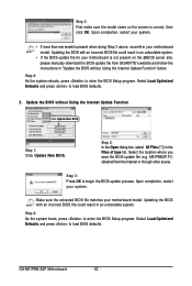
... 4: As the system boots, press to load BIOS defaults. 3. Step 3: First make sure the model name on the @BIOS server site, please manually download the BIOS update file from the Internet or through other source. Upon completion, restart your motherboard is not present on the screen is present... of type list. GA-M61PME-S2P Motherboard - 62 - Updating the BIOS with an incorrect BIOS file could result in an unbootable system. • If the BIOS update file for your system. • If more than one model is correct, then click OK. M61PME2P.F1) obtained from GIGABYTE's website and follow...
... 4: As the system boots, press to load BIOS defaults. 3. Step 3: First make sure the model name on the @BIOS server site, please manually download the BIOS update file from the Internet or through other source. Upon completion, restart your motherboard is not present on the screen is present... of type list. GA-M61PME-S2P Motherboard - 62 - Updating the BIOS with an incorrect BIOS file could result in an unbootable system. • If the BIOS update file for your system. • If more than one model is correct, then click OK. M61PME2P.F1) obtained from GIGABYTE's website and follow...

Manual
Page 67
... option screen when you can be set in kilobytes. Define a New Array - MediaShield ROM BIOS 6.94 Copyright (C) 2006 NVIDIA Corp. The striping block size can manually set the striping block size. Step 3: In the RAID Mode field, use the up or down arrow key to configure a RAID array. In the Striping...
... option screen when you can be set in kilobytes. Define a New Array - MediaShield ROM BIOS 6.94 Copyright (C) 2006 NVIDIA Corp. The striping block size can manually set the striping block size. Step 3: In the RAID Mode field, use the up or down arrow key to configure a RAID array. In the Striping...
Manual
Page 72
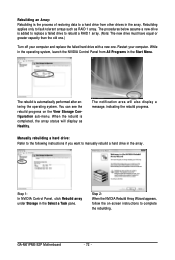
... in the array. GA-M61PME-S2P Motherboard - 72 - You can see the rebuild progress on -screen instructions to fault-tolerant arrays such as Healthy. Rebuilding an Array: Rebuilding is the process of restoring data to a hard drive from All Programs in the array. Manually rebuilding a hard drive...: Refer to the following instructions if you want to manually rebuild a hard drive in the Start Menu. Step 2: When the NVIDIA Rebuild Array Wizard appears, ...
... in the array. GA-M61PME-S2P Motherboard - 72 - You can see the rebuild progress on -screen instructions to fault-tolerant arrays such as Healthy. Rebuilding an Array: Rebuilding is the process of restoring data to a hard drive from All Programs in the array. Manually rebuilding a hard drive...: Refer to the following instructions if you want to manually rebuild a hard drive in the Start Menu. Step 2: When the NVIDIA Rebuild Array Wizard appears, ...
Manual
Page 74
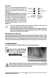
... back panel audio (only supported when using an HD front panel audio module), refer to the Mic in or Line in jack and manually configure the jack for microphone functionality. • Audio signals will appear in and out) to access the HD Audio Manager. High Definition...• To install a microphone, connect your operating system has been updated with the latest Service Pack for each jack through the audio driver. GA-M61PME-S2P Motherboard - 74 - Audio Jacks: The 5.1/7.1 surround cable adds additional three audio jacks to the right shows the default audio jack assignments. For ...
... back panel audio (only supported when using an HD front panel audio module), refer to the Mic in or Line in jack and manually configure the jack for microphone functionality. • Audio signals will appear in and out) to access the HD Audio Manager. High Definition...• To install a microphone, connect your operating system has been updated with the latest Service Pack for each jack through the audio driver. GA-M61PME-S2P Motherboard - 74 - Audio Jacks: The 5.1/7.1 surround cable adds additional three audio jacks to the right shows the default audio jack assignments. For ...
Manual
Page 84
... time of disposal will help to conserve natural resources and ensure that this text. GA-M61PME-S2P Motherboard - 84 - Moreover, we will be glad to develop products that do not use of our natural resources, GIGABYTE provides the following information on its packaging, which indicates that it is no longer ...recycling, reusing in your "end of life" product, you may contact us at the Customer Care number listed in your product's user's manual and we at the time of Certain Hazardous Substances in your effort. For more information about where you can drop off your waste equipment ...
... time of disposal will help to conserve natural resources and ensure that this text. GA-M61PME-S2P Motherboard - 84 - Moreover, we will be glad to develop products that do not use of our natural resources, GIGABYTE provides the following information on its packaging, which indicates that it is no longer ...recycling, reusing in your "end of life" product, you may contact us at the Customer Care number listed in your product's user's manual and we at the time of Certain Hazardous Substances in your effort. For more information about where you can drop off your waste equipment ...


