Manual
Page 4
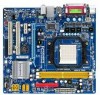
Table of Contents Box Contents ...6 OptionalItems ...6 GA-M61PME-S2P Motherboard Layout 7 Block Diagram ...8 Chapter 1 Hardware Installation 9 1-1 Installation Precautions 9 1-2 Product Specifications 10 1-3 Installing the CPU and CPU Cooler 12 1-3-1 Installing the CPU 12 1-3-2 Installing the CPU Cooler 14 1-4 Installing the Memory 15 1-4-1 Dual Channel Memory Configuration 15 1-4-2 Installing a Memory 16 1-5 Installing an Expansion Card 17 1-6 Back Panel Connectors 18...
Table of Contents Box Contents ...6 OptionalItems ...6 GA-M61PME-S2P Motherboard Layout 7 Block Diagram ...8 Chapter 1 Hardware Installation 9 1-1 Installation Precautions 9 1-2 Product Specifications 10 1-3 Installing the CPU and CPU Cooler 12 1-3-1 Installing the CPU 12 1-3-2 Installing the CPU Cooler 14 1-4 Installing the Memory 15 1-4-1 Dual Channel Memory Configuration 15 1-4-2 Installing a Memory 16 1-5 Installing an Expansion Card 17 1-6 Back Panel Connectors 18...
Manual
Page 9
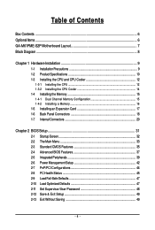
... about any metal leads or connectors. • It is best to wear an electrostatic discharge (ESD) wrist strap when handling electronic components such as a motherboard, CPU or memory. If you are connected tightly and securely. • When handling the motherboard, avoid touching any installation steps or have a problem related to the...
... about any metal leads or connectors. • It is best to wear an electrostatic discharge (ESD) wrist strap when handling electronic components such as a motherboard, CPU or memory. If you are connected tightly and securely. • When handling the motherboard, avoid touching any installation steps or have a problem related to the...
Manual
Page 10
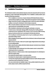
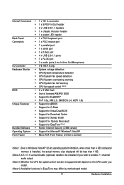
...processor/ AMD PhenomTM X3 processor/AMD AthlonTM X2 processor/ AMD AthlonTM processor/AMD SempronTM X2 processor/ AMD SempronTM processor (Go to GIGABYTE's website for the latest CPU support list.) 2000 MT/s NVIDIA® GeForce 6100/nForce 430 chipset 2 x 1.8V DDR2 DIMM sockets supporting up to ...-pin ATX main power connector 1 x 4-pin ATX 12V power connector 1 x floppy disk drive connector 1 x IDE connector 2 x SATA 3Gb/s connectors 1 x CPU fan header 1 x system fan header 1 x front panel header 1 x front panel audio header 1 x surround/center audio header GA-M61PME-S2P Motherboard - 10 -
...processor/ AMD PhenomTM X3 processor/AMD AthlonTM X2 processor/ AMD AthlonTM processor/AMD SempronTM X2 processor/ AMD SempronTM processor (Go to GIGABYTE's website for the latest CPU support list.) 2000 MT/s NVIDIA® GeForce 6100/nForce 430 chipset 2 x 1.8V DDR2 DIMM sockets supporting up to ...-pin ATX main power connector 1 x 4-pin ATX 12V power connector 1 x floppy disk drive connector 1 x IDE connector 2 x SATA 3Gb/s connectors 1 x CPU fan header 1 x system fan header 1 x front panel header 1 x front panel audio header 1 x surround/center audio header GA-M61PME-S2P Motherboard - 10 -
Manual
Page 11
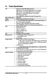
... iTE IT8718 chip Hardware Monitor System voltage detection CPU/System temperature detection CPU/System fan speed detection CPU/System overheating warning CPU/System fan fail warning CPU fan speed control (Note 3) BIOS 2 x 8 Mbit flash &#...optional) needs to be installed if you wish to enable 7.1-channel audio output. (Note 3) Whether the CPU fan speed control function is supported will depend on the CPU cooler you install. (Note 4) Available functions in EasyTune may differ by motherboard model. - 11 - Hardware...
... iTE IT8718 chip Hardware Monitor System voltage detection CPU/System temperature detection CPU/System fan speed detection CPU/System overheating warning CPU/System fan fail warning CPU fan speed control (Note 3) BIOS 2 x 8 Mbit flash &#...optional) needs to be installed if you wish to enable 7.1-channel audio output. (Note 3) Whether the CPU fan speed control function is supported will depend on the CPU cooler you install. (Note 4) Available functions in EasyTune may differ by motherboard model. - 11 - Hardware...
Manual
Page 12
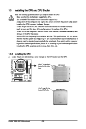
... Socket A Small Triangle Marking Denotes CPU Pin One AM2+/AM2 CPU GA-M61PME-S2P Motherboard - 12 - Locate the pin one of the CPU. A Small Triangle Mark Denotes Pin One of the CPU may occur. • Set the CPU host frequency in accordance with the CPU specifications. mended that the motherboard supports the CPU. (Go to GIGABYTE's website for the peripherals. If...
... Socket A Small Triangle Marking Denotes CPU Pin One AM2+/AM2 CPU GA-M61PME-S2P Motherboard - 12 - Locate the pin one of the CPU. A Small Triangle Mark Denotes Pin One of the CPU may occur. • Set the CPU host frequency in accordance with the CPU specifications. mended that the motherboard supports the CPU. (Go to GIGABYTE's website for the peripherals. If...
Manual
Page 13
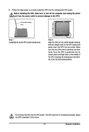
... one (small triangle marking) with the triangle mark on the middle of the CPU, lowering the locking lever and latching it into their holes. Do not force the CPU into the motherboard CPU socket. Before installing the CPU, make sure to turn off the computer and unplug the power cord from the... power outlet to prevent damage to correctly install the CPU into the CPU socket. Hardware Installation Follow the steps below ...
... one (small triangle marking) with the triangle mark on the middle of the CPU, lowering the locking lever and latching it into their holes. Do not force the CPU into the motherboard CPU socket. Before installing the CPU, make sure to turn off the computer and unplug the power cord from the... power outlet to prevent damage to correctly install the CPU into the CPU socket. Hardware Installation Follow the steps below ...
Manual
Page 14
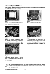
...GIGABYTE cooler as the picture above shows) to lock into place. (Refer to your CPU cooler installation manual for instructions on installing the cooler.) Step 5: Finally, attach the power connector of the CPU cooler to the mounting lug on the retention frame. Step 2: Place the CPU cooler on the motherboard. GA-M61PME-S2P... Motherboard - 14 - Step 3: Hook the CPU cooler clip to the CPU. Inadequately removing the CPU cooler may ...
...GIGABYTE cooler as the picture above shows) to lock into place. (Refer to your CPU cooler installation manual for instructions on installing the cooler.) Step 5: Finally, attach the power connector of the CPU cooler to the mounting lug on the retention frame. Step 2: Place the CPU cooler on the motherboard. GA-M61PME-S2P... Motherboard - 14 - Step 3: Hook the CPU cooler clip to the CPU. Inadequately removing the CPU cooler may ...
Manual
Page 15
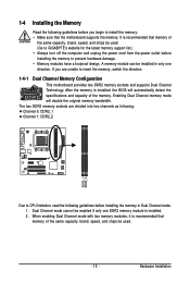
...design. When enabling Dual Channel mode with two memory modules, it is installed. 2. Hardware Installation The two DDR2 memory sockets are unable to CPU limitation, read the following guidelines before installing the memory in only one DDR2 memory module is recommended that memory of the same capacity, brand,... speed, and chips be used . (Go to GIGABYTE's website for the latest memory support list.) • Always turn off the computer and unplug the power cord from the power outlet before ...
...design. When enabling Dual Channel mode with two memory modules, it is installed. 2. Hardware Installation The two DDR2 memory sockets are unable to CPU limitation, read the following guidelines before installing the memory in only one DDR2 memory module is recommended that memory of the same capacity, brand,... speed, and chips be used . (Go to GIGABYTE's website for the latest memory support list.) • Always turn off the computer and unplug the power cord from the power outlet before ...
Manual
Page 21
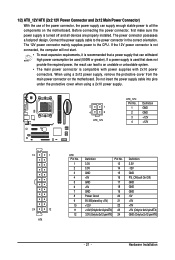
Connect the power supply cable to the CPU. If the 12V power connector is not connected, the computer will not start. • To meet expansion requirements, it is recommended that a power supply that ...
Connect the power supply cable to the CPU. If the 12V power connector is not connected, the computer will not start. • To meet expansion requirements, it is recommended that a power supply that ...
Manual
Page 22
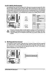
... are : 360 KB, 720 KB, 1.2 MB, 1.44 MB, and 2.88 MB. For optimum heat dissipation, it in damage to the CPU or the system may result in the correct orientation (the black connector wire is recommended that a system fan be installed inside the chassis. 1 ... Headers) The motherboard has a 4-pin CPU fan header (CPU_FAN) and a 3-pin system fan header (SYS_FAN). Do not place a jumper cap on the headers. 5) FDD (Floppy Disk Drive Connector) This connector is typically designated by a stripe of different color. 33 1 34 2 GA-M61PME-S2P Motherboard - 22 - Most fan headers ...
... are : 360 KB, 720 KB, 1.2 MB, 1.44 MB, and 2.88 MB. For optimum heat dissipation, it in damage to the CPU or the system may result in the correct orientation (the black connector wire is recommended that a system fan be installed inside the chassis. 1 ... Headers) The motherboard has a 4-pin CPU fan header (CPU_FAN) and a 3-pin system fan header (SYS_FAN). Do not place a jumper cap on the headers. 5) FDD (Floppy Disk Drive Connector) This connector is typically designated by a stripe of different color. 33 1 34 2 GA-M61PME-S2P Motherboard - 22 - Most fan headers ...
Manual
Page 34
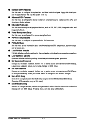
... Setup Save all the changes made in the BIOS Setup program to the CMOS and exit BIOS Setup. (Pressing can also carry out this task.) GA-M61PME-S2P Motherboard - 34 - A supervisor password allows you to view the BIOS settings but not to make changes in BIOS Setup. Set User ... Use this menu to configure the system's PCI & PnP resources. PC Health Status Use this menu to see information about autodetected system/CPU temperature, system voltage and fan speed, etc. Load Fail-Safe Defaults Fail-Safe defaults are factory settings for the most stable, minimal-...
... Setup Save all the changes made in the BIOS Setup program to the CMOS and exit BIOS Setup. (Pressing can also carry out this task.) GA-M61PME-S2P Motherboard - 34 - A supervisor password allows you to view the BIOS settings but not to make changes in BIOS Setup. Set User ... Use this menu to configure the system's PCI & PnP resources. PC Health Status Use this menu to see information about autodetected system/CPU temperature, system voltage and fan speed, etc. Load Fail-Safe Defaults Fail-Safe defaults are factory settings for the most stable, minimal-...
Manual
Page 37
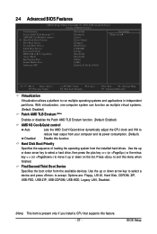
... disables the Patch AMD TLB Erratum function. (Default: Enabled) AMD K8 Cool&Quiet control Auto Lets the AMD Cool'n'Quiet driver dynamically adjust the CPU clock and VIA to reduce heat output from the available devices. Use the up or down arrow key to select a hard drive, then press ..., Hard Disk, CDROM, ZIP, USB-FDD, USB-ZIP, USB-CDROM, USB-HDD, Legacy LAN, Disabled. (Note) This item is present only if you install a CPU that supports this function. Hard Disk Boot Priority Specifies the sequence of loading the operating system from the installed hard drives. Press to run multiple...
... disables the Patch AMD TLB Erratum function. (Default: Enabled) AMD K8 Cool&Quiet control Auto Lets the AMD Cool'n'Quiet driver dynamically adjust the CPU clock and VIA to reduce heat output from the available devices. Use the up or down arrow key to select a hard drive, then press ..., Hard Disk, CDROM, ZIP, USB-FDD, USB-ZIP, USB-CDROM, USB-HDD, Legacy LAN, Disabled. (Note) This item is present only if you install a CPU that supports this function. Hard Disk Boot Priority Specifies the sequence of loading the operating system from the installed hard drives. Press to run multiple...
Manual
Page 45
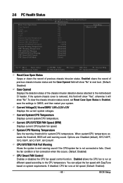
...or fan connection when this field will show "Yes", otherwise it will emit warning sound. BIOS Setup System/CPU Warning Temperature Sets the warning threshold for system/CPU temperature. 2-8 PC Health Status CMOS Setup Utility-Copyright (C) 1984-2008 Award Software PC Health Status Reset Case...Opened Vcore DDR2 1.8V +3.3V +12V Current System Temperature Current CPU Temperature Current CPU FAN Speed Current SYSTEM FAN Speed System Warning Temperature CPU Warning Temperature CPU FAN Fail Warning SYSTEM FAN Fail Warning CPU Smart FAN Control CPU Smart FAN Mode [Disabled] Yes OK OK OK OK 32oC ...
...or fan connection when this field will show "Yes", otherwise it will emit warning sound. BIOS Setup System/CPU Warning Temperature Sets the warning threshold for system/CPU temperature. 2-8 PC Health Status CMOS Setup Utility-Copyright (C) 1984-2008 Award Software PC Health Status Reset Case...Opened Vcore DDR2 1.8V +3.3V +12V Current System Temperature Current CPU Temperature Current CPU FAN Speed Current SYSTEM FAN Speed System Warning Temperature CPU Warning Temperature CPU FAN Fail Warning SYSTEM FAN Fail Warning CPU Smart FAN Control CPU Smart FAN Mode [Disabled] Yes OK OK OK OK 32oC ...
Manual
Page 46
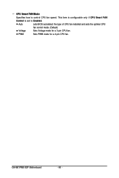
PWM Sets PWM mode for a 3-pin CPU fan. GA-M61PME-S2P Motherboard - 46 - This item is configurable only if CPU Smart FAN Control is set to control CPU fan speed. Auto Lets BIOS autodetect the type of CPU fan installed and sets the optimal CPU fan control mode. (Default) Voltage Sets Voltage mode for a 4-pin CPU fan. CPU Smart FAN Mode Specifies how to Enabled.
PWM Sets PWM mode for a 3-pin CPU fan. GA-M61PME-S2P Motherboard - 46 - This item is configurable only if CPU Smart FAN Control is set to control CPU fan speed. Auto Lets BIOS autodetect the type of CPU fan installed and sets the optimal CPU fan control mode. (Default) Voltage Sets Voltage mode for a 4-pin CPU fan. CPU Smart FAN Mode Specifies how to Enabled.
Manual
Page 63
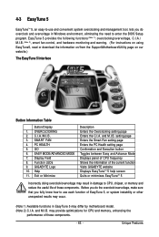
...page Confirmation and Execution button Toggles between Easy and Advance Mode Displays panel of CPU frequency Shows the information of the current function Visits GIGABYTE website Displays EasyTuneTM 5 help screen Quits or minimizes EasyTuneTM 5 Incorrectly doing overclock... may differ by motherboard model. (Note 2) C.I.A. OVERCLOCKING 2. PC HEALTH 5. GIGABYTE Logo 10. Help 11. Exit or Minimize Description Enters the Overclocking setting page Enters the C.I .B. 3. may provide optimizations for CPU and memory, enhancing the performance of these components. - 63 - C.I.A./M.I .A. Function...
...page Confirmation and Execution button Toggles between Easy and Advance Mode Displays panel of CPU frequency Shows the information of the current function Visits GIGABYTE website Displays EasyTuneTM 5 help screen Quits or minimizes EasyTuneTM 5 Incorrectly doing overclock... may differ by motherboard model. (Note 2) C.I.A. OVERCLOCKING 2. PC HEALTH 5. GIGABYTE Logo 10. Help 11. Exit or Minimize Description Enters the Overclocking setting page Enters the C.I .B. 3. may provide optimizations for CPU and memory, enhancing the performance of these components. - 63 - C.I.A./M.I .A. Function...
Manual
Page 82
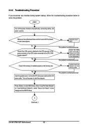
... memory is verified and solved. Yes Isolate the short circuit. The problem is installed properly on the memory slot. Connect the CPU cooler power cable to the CPU_FAN header properly? A (Continued...) GA-M61PME-S2P Motherboard - 82 - 5-3-2 Troubleshooting Procedure If you encounter any troubles during system startup, follow the troubleshooting procedure below to save changes...
... memory is verified and solved. Yes Isolate the short circuit. The problem is installed properly on the memory slot. Connect the CPU cooler power cable to the CPU_FAN header properly? A (Continued...) GA-M61PME-S2P Motherboard - 82 - 5-3-2 Troubleshooting Procedure If you encounter any troubles during system startup, follow the troubleshooting procedure below to save changes...
Manual
Page 83
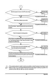
...your question. Check if the system can boot successfully. Appendix Yes Check if there is unable to solve your monitor. The problem is the CPU cooler running? No The keyboard or mouse might fail. The problem is verified and solved. Yes Reinstall the operating system. Or go to ...the Support\Technical Service Zone page to save changes and exit BIOS Setup. No The power supply, CPU or CPU socket might fail. Yes Turn off the computer and connect the IDE/SATA devices. No The graphics card, expansion slot, or monitor might ...
...your question. Check if the system can boot successfully. Appendix Yes Check if there is unable to solve your monitor. The problem is the CPU cooler running? No The keyboard or mouse might fail. The problem is verified and solved. Yes Reinstall the operating system. Or go to ...the Support\Technical Service Zone page to save changes and exit BIOS Setup. No The power supply, CPU or CPU socket might fail. Yes Turn off the computer and connect the IDE/SATA devices. No The graphics card, expansion slot, or monitor might ...


