Manual
Page 3
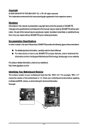
..., copied, translated, transmitted, or published in this manual is 1.0. Disclaimer Information in the use GIGABYTE's unique features, read or download the information on/from the Support\Motherboard\Technology Guide page on your motherboard revision before updating motherboard BIOS, drivers, or when looking for technical information. Documentation Classifications In order to their respective...
..., copied, translated, transmitted, or published in this manual is 1.0. Disclaimer Information in the use GIGABYTE's unique features, read or download the information on/from the Support\Motherboard\Technology Guide page on your motherboard revision before updating motherboard BIOS, drivers, or when looking for technical information. Documentation Classifications In order to their respective...
Manual
Page 4
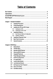
Table of Contents Box Contents ...6 OptionalItems ...6 GA-M61PME-S2P Motherboard Layout 7 Block Diagram ...8 Chapter 1 Hardware Installation 9 1-1 Installation Precautions 9 1-2 Product Specifications 10 1-3 Installing the CPU and CPU Cooler 12... Memory 16 1-5 Installing an Expansion Card 17 1-6 Back Panel Connectors 18 1-7 Internal Connectors 20 Chapter 2 BIOS Setup 31 2-1 Startup Screen 32 2-2 The Main Menu 33 2-3 Standard CMOS Features 35 2-4 Advanced BIOS Features 37 2-5 IntegratedPeripherals 39 2-6 Power Management Setup 42 2-7 PnP/PCI Configurations 44 2-8 PC Health Status...
Table of Contents Box Contents ...6 OptionalItems ...6 GA-M61PME-S2P Motherboard Layout 7 Block Diagram ...8 Chapter 1 Hardware Installation 9 1-1 Installation Precautions 9 1-2 Product Specifications 10 1-3 Installing the CPU and CPU Cooler 12... Memory 16 1-5 Installing an Expansion Card 17 1-6 Back Panel Connectors 18 1-7 Internal Connectors 20 Chapter 2 BIOS Setup 31 2-1 Startup Screen 32 2-2 The Main Menu 33 2-3 Standard CMOS Features 35 2-4 Advanced BIOS Features 37 2-5 IntegratedPeripherals 39 2-6 Power Management Setup 42 2-7 PnP/PCI Configurations 44 2-8 PC Health Status...
Manual
Page 5
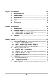
... 52 3-3 Technical Manuals 52 3-4 Contact ...53 3-5 System ...53 3-6 Download Center 54 Chapter 4 Unique Features 55 4-1 Xpress Recovery2 55 4-2 BIOS Update Utilities 58 4-2-1 Updating the BIOS with the Q-Flash Utility 58 4-2-2 Updating the BIOS with the @BIOS Utility 61 4-3 EasyTune 5 ...63 Chapter 5 Appendix ...65 5-1 Configuring SATA Hard Drive(s 65 5-1-1 Configuring the Onboard SATA Controller 65...
... 52 3-3 Technical Manuals 52 3-4 Contact ...53 3-5 System ...53 3-6 Download Center 54 Chapter 4 Unique Features 55 4-1 Xpress Recovery2 55 4-2 BIOS Update Utilities 58 4-2-1 Updating the BIOS with the Q-Flash Utility 58 4-2-2 Updating the BIOS with the @BIOS Utility 61 4-3 EasyTune 5 ...63 Chapter 5 Appendix ...65 5-1 Configuring SATA Hard Drive(s 65 5-1-1 Configuring the Onboard SATA Controller 65...
Manual
Page 11
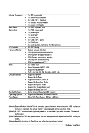
... fail warning CPU fan speed control (Note 3) BIOS 2 x 8 Mbit flash Use of licensed AWARD BIOS Support for DualBIOSTM PnP 1.0a, DMI 2.0, SM BIOS 2.4, ACPI 1.0b Unique Features Support for @BIOS Support for Q-Flash Support for Virtual Dual BIOS Support for Download Center Support for Xpress...
... fail warning CPU fan speed control (Note 3) BIOS 2 x 8 Mbit flash Use of licensed AWARD BIOS Support for DualBIOSTM PnP 1.0a, DMI 2.0, SM BIOS 2.4, ACPI 1.0b Unique Features Support for @BIOS Support for Q-Flash Support for Virtual Dual BIOS Support for Download Center Support for Xpress...
Manual
Page 15
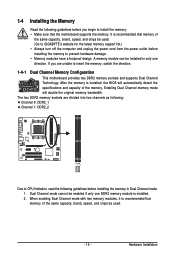
... installed, the BIOS will double the original memory bandwidth. When enabling Dual Channel mode with two memory modules, it is recommended that memory of the same capacity, brand, speed, and chips be installed in Dual Channel mode. 1. It is installed. 2. Hardware Installation A memory module can be used . (Go to GIGABYTE's website for...
... installed, the BIOS will double the original memory bandwidth. When enabling Dual Channel mode with two memory modules, it is recommended that memory of the same capacity, brand, speed, and chips be installed in Dual Channel mode. 1. It is installed. 2. Hardware Installation A memory module can be used . (Go to GIGABYTE's website for...
Manual
Page 17
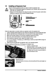
...card straight out from the slot. - 17 - Turn on the card are completely inserted into the PCI Express x16 slot. If necessary, go to BIOS Setup to the chassis back panel with the expansion card in the slot. 3. Install the driver provided with a screw. 5. Align the card with ...8226; Always turn off the computer and unplug the power cord from the chassis back panel. 2. Secure the card's metal bracket to make any required BIOS changes for your card. Make sure the card is fully inserted into the slot. 4. Carefully read the manual that supports your expansion card(s). 7. ...
...card straight out from the slot. - 17 - Turn on the card are completely inserted into the PCI Express x16 slot. If necessary, go to BIOS Setup to the chassis back panel with the expansion card in the slot. 3. Install the driver provided with a screw. 5. Align the card with ...8226; Always turn off the computer and unplug the power cord from the chassis back panel. 2. Secure the card's metal bracket to make any required BIOS changes for your card. Make sure the card is fully inserted into the slot. 4. Carefully read the manual that supports your expansion card(s). 7. ...
Manual
Page 24
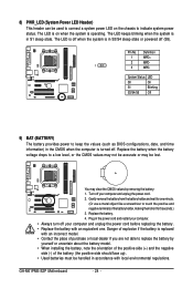
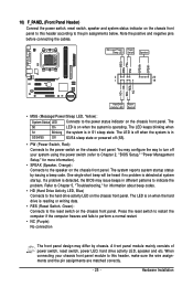
... seconds.) 3. System Status LED S0 On S1 Blinking S3/S4/S5 Off 9) BAT (BATTERY) The battery provides power to keep the values (such as BIOS configurations, date, and time information) in S1 sleep state. Turn off your computer and unplug the power cord. 2. Danger of explosion if the battery is... off (S5). 8) PWR_LED (System Power LED Header) This header can be used to connect a system power LED on when the system is operating. GA-M61PME-S2P Motherboard - 24 - Pin No. The LED is on the chassis to indicate system power status. Definition 1 MPD+ 2 MPD- 1 3 MPD-
... seconds.) 3. System Status LED S0 On S1 Blinking S3/S4/S5 Off 9) BAT (BATTERY) The battery provides power to keep the values (such as BIOS configurations, date, and time information) in S1 sleep state. Turn off your computer and unplug the power cord. 2. Danger of explosion if the battery is... off (S5). 8) PWR_LED (System Power LED Header) This header can be used to connect a system power LED on when the system is operating. GA-M61PME-S2P Motherboard - 24 - Pin No. The LED is on the chassis to indicate system power status. Definition 1 MPD+ 2 MPD- 1 3 MPD-
Manual
Page 25
.... One single short beep will be heard if no problem is operating. When connecting your system using the power switch (refer to Chapter 2, "BIOS Setup," "Power Management Setup," for information about beep codes. • HD (Hard Drive Activity LED, Blue) Connects to the power status indicator...Chapter 5, "Troubleshooting," for more information). • SPEAK (Speaker, Orange): Connects to the speaker on when the hard drive is detected, the BIOS may differ by issuing a beep code. The LED is on the chassis front panel. Message/Power/ Power Sleep LED Switch Speaker MSG+ MSG-
.... One single short beep will be heard if no problem is operating. When connecting your system using the power switch (refer to Chapter 2, "BIOS Setup," "Power Management Setup," for information about beep codes. • HD (Hard Drive Activity LED, Blue) Connects to the power status indicator...Chapter 5, "Troubleshooting," for more information). • SPEAK (Speaker, Orange): Connects to the speaker on when the hard drive is detected, the BIOS may differ by issuing a beep code. The LED is on the chassis front panel. Message/Power/ Power Sleep LED Switch Speaker MSG+ MSG-
Manual
Page 29
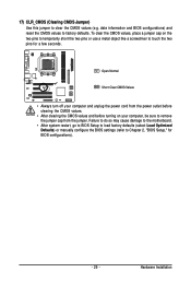
...defaults. Failure to do so may cause damage to the motherboard. • After system restart, go to BIOS Setup to load factory defaults (select Load Optimized Defaults) or manually configure the BIOS settings (refer to clear the CMOS values (e.g. 17) CLR_CMOS (Clearing CMOS Jumper) Use this jumper to ...Chapter 2, "BIOS Setup," for a few seconds. date information and BIOS configurations) and reset the CMOS values to remove the jumper cap from the jumper. To clear the CMOS values, place a jumper ...
...defaults. Failure to do so may cause damage to the motherboard. • After system restart, go to BIOS Setup to load factory defaults (select Load Optimized Defaults) or manually configure the BIOS settings (refer to clear the CMOS values (e.g. 17) CLR_CMOS (Clearing CMOS Jumper) Use this jumper to ...Chapter 2, "BIOS Setup," for a few seconds. date information and BIOS configurations) and reset the CMOS values to remove the jumper cap from the jumper. To clear the CMOS values, place a jumper ...
Manual
Page 31
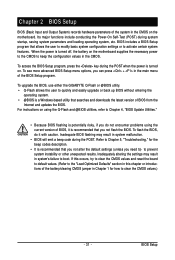
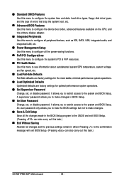
... system's failure to quickly and easily upgrade or back up BIOS without entering the operating system. • @BIOS is recommended that searches and downloads the latest version of BIOS from the Internet and updates the BIOS. To upgrade the BIOS, use either the GIGABYTE Q-Flash or @BIOS utility. • Q-Flash allows the user to boot. If this...
... system's failure to quickly and easily upgrade or back up BIOS without entering the operating system. • @BIOS is recommended that searches and downloads the latest version of BIOS from the Internet and updates the BIOS. To upgrade the BIOS, use either the GIGABYTE Q-Flash or @BIOS utility. • Q-Flash allows the user to boot. If this...
Manual
Page 32
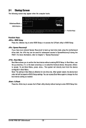
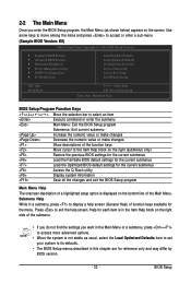
... directly boot from the device configured in Boot Menu. GA-M61PME-S2P Motherboard - 32 - Note: The setting in BIOS Setup. : Xpress Recovery2 If you to set the first boot device without having to accept. You can be based on BIOS Setup settings. The system will still be used for...needed. : Q-Flash Press the key to XpressRecovery2 during the POST. GA-M61PME-S2P E8 . . . . : BIOS Setup : XpressRecovery2 : Boot Menu : Qflash 12/16/2008-NV-MCP61-6A61KG0AC-00 Function Keys Function Keys: : BIOS Setup Press the key to enter BIOS Setup or to access the Q-Flash utility in Boot Menu is ...
... directly boot from the device configured in Boot Menu. GA-M61PME-S2P Motherboard - 32 - Note: The setting in BIOS Setup. : Xpress Recovery2 If you to set the first boot device without having to accept. You can be based on BIOS Setup settings. The system will still be used for...needed. : Q-Flash Press the key to XpressRecovery2 during the POST. GA-M61PME-S2P E8 . . . . : BIOS Setup : XpressRecovery2 : Boot Menu : Qflash 12/16/2008-NV-MCP61-6A61KG0AC-00 Function Keys Function Keys: : BIOS Setup Press the key to enter BIOS Setup or to access the Q-Flash utility in Boot Menu is ...
Manual
Page 33
...item is in the Item Help block on the right side of the Main Menu. BIOS Setup Program Function Keys Move the selection bar to select an item Execute command or enter the submenu Main ...Menu: Exit the BIOS Setup program Submenus: Exit current submenu Increase the numeric value or make changes Decrease the numeric ...bottom line of the submenu. • If you do not find the settings you enter the BIOS Setup program, the Main Menu (as usual, select the Load Optimized Defaults item to set your system to its ...
...item is in the Item Help block on the right side of the Main Menu. BIOS Setup Program Function Keys Move the selection bar to select an item Execute command or enter the submenu Main ...Menu: Exit the BIOS Setup program Submenus: Exit current submenu Increase the numeric value or make changes Decrease the numeric ...bottom line of the submenu. • If you do not find the settings you enter the BIOS Setup program, the Main Menu (as usual, select the Load Optimized Defaults item to set your system to its ...
Manual
Page 34
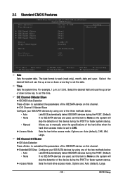
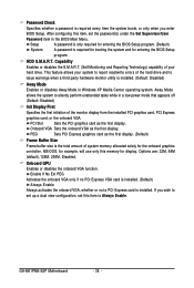
... for optimal-performance system operations. Set Supervisor Password Change, set , or disable password. Pressing to the confirmation message will exit BIOS Setup. (Pressing can also carry out this task.) GA-M61PME-S2P Motherboard - 34 - Standard CMOS Features Use this menu to configure the system time and date, hard drive types, floppy disk...
... for optimal-performance system operations. Set Supervisor Password Change, set , or disable password. Pressing to the confirmation message will exit BIOS Setup. (Pressing can also carry out this task.) GA-M61PME-S2P Motherboard - 34 - Standard CMOS Features Use this menu to configure the system time and date, hard drive types, floppy disk...
Manual
Page 35
...set to set the date. Extended IDE Drive Configure your IDE/SATA devices by using one of the two methods below : • Auto Lets BIOS automatically detect IDE/SATA devices during the POST. (Default) • None If no IDE/SATA devices are used , set this item to ...autodetect the parameters of the three methods below : • Auto Lets BIOS automatically detect IDE/SATA devices during the POST for faster system startup. IDE Channel 0 Master/Slave Configure your IDE/SATA devices by using one of...
...set to set the date. Extended IDE Drive Configure your IDE/SATA devices by using one of the two methods below : • Auto Lets BIOS automatically detect IDE/SATA devices during the POST. (Default) • None If no IDE/SATA devices are used , set this item to ...autodetect the parameters of the three methods below : • Auto Lets BIOS automatically detect IDE/SATA devices during the POST for faster system startup. IDE Channel 0 Master/Slave Configure your IDE/SATA devices by using one of...
Manual
Page 36
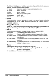
...to specify whether the installed floppy disk drive is 3-mode floppy disk drive, a Japanese standard floppy disk drive. Options are determined by the BIOS POST. Sector Number of cylinders. Floppy 3 Mode Support Allows you do not install a floppy disk drive, set this item to the ...error. If you to selects the type of extended memory. Options are: None, 360K/5.25", 1.2M/5.25", 720K/3.5", 1.44M/3.5", 2.88M/3.5". GA-M61PME-S2P Motherboard - 36 - If you to determine whether the system will not stop for the MS-DOS operating system. Head Number of the currently ...
...to specify whether the installed floppy disk drive is 3-mode floppy disk drive, a Japanese standard floppy disk drive. Options are determined by the BIOS POST. Sector Number of cylinders. Floppy 3 Mode Support Allows you do not install a floppy disk drive, set this item to the ...error. If you to selects the type of extended memory. Options are: None, 360K/5.25", 1.2M/5.25", 720K/3.5", 1.44M/3.5", 2.88M/3.5". GA-M61PME-S2P Motherboard - 36 - If you to determine whether the system will not stop for the MS-DOS operating system. Head Number of the currently ...
Manual
Page 37
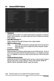
... CMOS Setup Utility-Copyright (C) 1984-2008 Award Software Advanced BIOS Features Virtualization Patch AMD TLB Erratum (Note) AMD K8 Cool&Quiet control Hard Disk Boot Priority First Boot Device Second Boot Device Third Boot ..., USB-ZIP, USB-CDROM, USB-HDD, Legacy LAN, Disabled. (Note) This item is present only if you install a CPU that supports this menu when finished. BIOS Setup With virtualization, one computer system can function as multiple virtual systems. (Default: Disabled) Patch AMD TLB Erratum (Note) Enables or disables the Patch AMD...
... CMOS Setup Utility-Copyright (C) 1984-2008 Award Software Advanced BIOS Features Virtualization Patch AMD TLB Erratum (Note) AMD K8 Cool&Quiet control Hard Disk Boot Priority First Boot Device Second Boot Device Third Boot ..., USB-ZIP, USB-CDROM, USB-HDD, Legacy LAN, Disabled. (Note) This item is present only if you install a CPU that supports this menu when finished. BIOS Setup With virtualization, one computer system can function as multiple virtual systems. (Default: Disabled) Patch AMD TLB Erratum (Note) Enables or disables the Patch AMD...
Manual
Page 38
...installed. (Default) Always Enable Always activates the onboard VGA, whether or not a PCI Express card is required for booting the system and for entering the BIOS Setup program. HDD S.M.A.R.T. Options are: 32M, 64M (default), 128M, 256M, Disabled. After configuring this item to set up a dual view configuration, set... unattended tasks while in Windows XP Media Center operating system. PCI Slot Sets the PCI graphics card as the first display. GA-M61PME-S2P Motherboard - 38 - This feature allows your hard drive. Onboard GPU Enables or disables the onboard VGA function.
...installed. (Default) Always Enable Always activates the onboard VGA, whether or not a PCI Express card is required for booting the system and for entering the BIOS Setup program. HDD S.M.A.R.T. Options are: 32M, 64M (default), 128M, 256M, Disabled. After configuring this item to set up a dual view configuration, set... unattended tasks while in Windows XP Media Center operating system. PCI Slot Sets the PCI graphics card as the first display. GA-M61PME-S2P Motherboard - 38 - This feature allows your hard drive. Onboard GPU Enables or disables the onboard VGA function.
Manual
Page 39
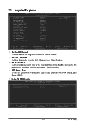
BIOS Setup 2-5 Integrated Peripherals CMOS Setup Utility-Copyright (C) 1984-2008 Award Software Integrated Peripherals On-Chip IDE Channel NV SATA Controller IDE Prefetch Mode USB Memory ...
BIOS Setup 2-5 Integrated Peripherals CMOS Setup Utility-Copyright (C) 1984-2008 Award Software Integrated Peripherals On-Chip IDE Channel NV SATA Controller IDE Prefetch Mode USB Memory ...

Manual
Page 41
USB Keyboard Support Allows USB keyboard to be used in MS-DOS. (Default: Disabled) USB Mouse Support Allows USB mouse to be used in MS-DOS. (Default: Disabled) Legacy USB storage detect Determines whether to detect USB storage devices, including USB flash drives and USB hard drives during the POST. (Default: Enabled) - 41 - BIOS Setup
USB Keyboard Support Allows USB keyboard to be used in MS-DOS. (Default: Disabled) USB Mouse Support Allows USB mouse to be used in MS-DOS. (Default: Disabled) Legacy USB storage detect Determines whether to detect USB storage devices, including USB flash drives and USB hard drives during the POST. (Default: Enabled) - 41 - BIOS Setup
Manual
Page 43
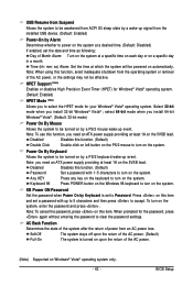
... to turn on the system, enter the password and press . Note: To cancel the password, press on Windows® Vista® operating system only. - 43 - BIOS Setup Note: When using this function, you need an ATX power supply providing at least 1A on the 5VSB lead. select 64-bit mode when...
... to turn on the system, enter the password and press . Note: To cancel the password, press on Windows® Vista® operating system only. - 43 - BIOS Setup Note: When using this function, you need an ATX power supply providing at least 1A on the 5VSB lead. select 64-bit mode when...


