Manual
Page 1
GA-M61PM-S2 (rev. 2.0) AMD Socket AM2 Processor Motherboard User's Manual Rev. 2002 12ME-M61PMS2-2002R * The WEEE marking on the product indicates this product must not be disposed of with user's other household waste and must be handed over to a designated collection point for the recycling of waste electrical and electronic equipment!! * The WEEE marking applies only in European Union's member states.
GA-M61PM-S2 (rev. 2.0) AMD Socket AM2 Processor Motherboard User's Manual Rev. 2002 12ME-M61PMS2-2002R * The WEEE marking on the product indicates this product must not be disposed of with user's other household waste and must be handed over to a designated collection point for the recycling of waste electrical and electronic equipment!! * The WEEE marking applies only in European Union's member states.

Manual
Page 2
Motherboard GA-M61PM-S2 (rev. 2.0) Nov. 29, 2006 Motherboard GA-M61PM-S2 (rev. 2.0) Nov. 29, 2006
Motherboard GA-M61PM-S2 (rev. 2.0) Nov. 29, 2006 Motherboard GA-M61PM-S2 (rev. 2.0) Nov. 29, 2006
Manual
Page 4
Table of Contents ItemChecklist ...6 OptionalAccessories ...6 GA-M61PM-S2 (rev. 2.0) Motherboard Layout 7 Block Diagram ...8 Chapter 1 Hardware Installation 9 1-1 Considerations Prior to Installation 9 1-2 Feature Summary 10 1-3 Installation of the CPU and CPU Cooler 12 1-3-1 Installation of the CPU ...
Table of Contents ItemChecklist ...6 OptionalAccessories ...6 GA-M61PM-S2 (rev. 2.0) Motherboard Layout 7 Block Diagram ...8 Chapter 1 Hardware Installation 9 1-1 Considerations Prior to Installation 9 1-2 Feature Summary 10 1-3 Installation of the CPU and CPU Cooler 12 1-3-1 Installation of the CPU ...
Manual
Page 7
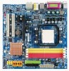
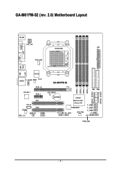
GA-M61PM-S2 (rev. 2.0) Motherboard Layout VGA COMA LPT USB USB 1394 LAN KB_MS ATX_12V Socket AM2 ATX CPU_FAN IT8716 AUDIO F_AUDIO BIOS CI PCIE_16 GA-M61PM-S2 RTL8211 PCIE_1 PCI1 CD_IN PCI2 CODEC REV: 2.0 SPDIF_IO COMB CLR_CMOS BATTERY nVIDIA® GeForce 6100/ nForce 430 TSB43AB23 F1_1394 F2_1394 SYS_FAN IDE FDD F_USB2 F_USB1 F_USB3 F_PANEL PWR_LED DDRII_1 DDRII_2 DDRII_3 DDRII_4 SATAII1 SATAII3 SATAII0 SATAII2 - 7 -
GA-M61PM-S2 (rev. 2.0) Motherboard Layout VGA COMA LPT USB USB 1394 LAN KB_MS ATX_12V Socket AM2 ATX CPU_FAN IT8716 AUDIO F_AUDIO BIOS CI PCIE_16 GA-M61PM-S2 RTL8211 PCIE_1 PCI1 CD_IN PCI2 CODEC REV: 2.0 SPDIF_IO COMB CLR_CMOS BATTERY nVIDIA® GeForce 6100/ nForce 430 TSB43AB23 F1_1394 F2_1394 SYS_FAN IDE FDD F_USB2 F_USB1 F_USB3 F_PANEL PWR_LED DDRII_1 DDRII_2 DDRII_3 DDRII_4 SATAII1 SATAII3 SATAII0 SATAII2 - 7 -

Manual
Page 9
...) cuff when handling electronic components (CPU, RAM). 4. English Chapter 1 Hardware Installation 1-1 Considerations Prior to Installation Preparing Your Computer The motherboard contains numerous delicate electronic circuits and components which can lead to damage to system components as well as physical harm to the user. ... there are connected. 4. Please do not allow screws to improper installation. 4. Damage due to be an unofficial Gigabyte product. - 9 - Damage as a result of the motherboard or any metal leads or connectors. 3. Damage due to come in the user manual. 3.
...) cuff when handling electronic components (CPU, RAM). 4. English Chapter 1 Hardware Installation 1-1 Considerations Prior to Installation Preparing Your Computer The motherboard contains numerous delicate electronic circuits and components which can lead to damage to system components as well as physical harm to the user. ... there are connected. 4. Please do not allow screws to improper installation. 4. Damage due to be an unofficial Gigabyte product. - 9 - Damage as a result of the motherboard or any metal leads or connectors. 3. Damage due to come in the user manual. 3.

Manual
Page 10
... Š 1 CD In connector Š 3 USB 2.0/1.1 connectors for additional 6 USB 2.0/1.1 ports by cable Š 1 COMB connector Š 1 power LED connector Š 1 Chassis Intrusion connector GA-M61PM-S2 (rev. 2.0) Motherboard - 10 - TSB43AB23 chip Š 3 IEEE 1394a ports Storage Š nVIDIA® GeForce 6100/nForce 430 chipset - 1 FDD connector, allowing connection of 1 FDD device - 1 IDE connector...
... Š 1 CD In connector Š 3 USB 2.0/1.1 connectors for additional 6 USB 2.0/1.1 ports by cable Š 1 COMB connector Š 1 power LED connector Š 1 Chassis Intrusion connector GA-M61PM-S2 (rev. 2.0) Motherboard - 10 - TSB43AB23 chip Š 3 IEEE 1394a ports Storage Š nVIDIA® GeForce 6100/nForce 430 chipset - 1 FDD connector, allowing connection of 1 FDD device - 1 IDE connector...

Manual
Page 11
... is installed, the actual memory available for the operating system will depend on the CPU you install. (Note 3) EasyTune functions may vary depending on different motherboards. - 11 - English Rear Panel I/O Š 1 PS/2 keyboard port Š 1 PS/2 mouse port Š 1 parallel port Š 1 COMA port Š 1 IEEE 1394a port Š 4 USB 2.0/1.1 ports...
... is installed, the actual memory available for the operating system will depend on the CPU you install. (Note 3) EasyTune functions may vary depending on different motherboards. - 11 - English Rear Panel I/O Š 1 PS/2 keyboard port Š 1 PS/2 mouse port Š 1 parallel port Š 1 COMA port Š 1 IEEE 1394a port Š 4 USB 2.0/1.1 ports...
Manual
Page 12
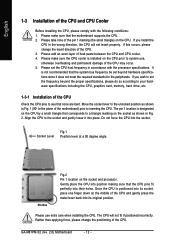
... Align the CPU to system use extra care when installing the CPU. Socket Lever Fig.1 Position lever at a 90 degree angle. GA-M61PM-S2 (rev. 2.0) Motherboard - 12 - English 1-3 Installation of the CPU and CPU Cooler Before installing the CPU, please comply with the processor specifications. Please... pins fit perfectly into place. The CPU will not insert properly. Gently place the CPU into position making sure that the motherboard supports the CPU. 2. If you wish to set beyond the proper specifications, please do so according to your hardware specifications ...
... Align the CPU to system use extra care when installing the CPU. Socket Lever Fig.1 Position lever at a 90 degree angle. GA-M61PM-S2 (rev. 2.0) Motherboard - 12 - English 1-3 Installation of the CPU and CPU Cooler Before installing the CPU, please comply with the processor specifications. Please... pins fit perfectly into place. The CPU will not insert properly. Gently place the CPU into position making sure that the motherboard supports the CPU. 2. If you wish to set beyond the proper specifications, please do so according to your hardware specifications ...

Manual
Page 13
... the CPU. English 1-3-2 Installation of the CPU Cooler Fig.1 Before installing the CPU cooler, please first add an even layer of heat paste on the motherboard so that either thermal tape rather than heat paste be used for detailed installation instructions). Hardware Installation To prevent such an occurrence, it is suggested...
... the CPU. English 1-3-2 Installation of the CPU Cooler Fig.1 Before installing the CPU cooler, please first add an even layer of heat paste on the motherboard so that either thermal tape rather than heat paste be used for detailed installation instructions). Hardware Installation To prevent such an occurrence, it is suggested...

Manual
Page 14
...be installed in only one direction. English 1-4 Installation of Memory Before installing the memory modules, please comply with each slot. The motherboard supports DDRII memory modules, whereby BIOS will automatically detect memory capacity and specifications. Then push it down. If you wish to insert... recommended that memory of the DIMM sockets to prevent hardware damage. 3. Memory modules have a foolproof insertion design. GA-M61PM-S2 (rev. 2.0) Motherboard - 14 - Before installing or removing memory modules, please make sure that they can be used is supported by the...
...be installed in only one direction. English 1-4 Installation of Memory Before installing the memory modules, please comply with each slot. The motherboard supports DDRII memory modules, whereby BIOS will automatically detect memory capacity and specifications. Then push it down. If you wish to insert... recommended that memory of the DIMM sockets to prevent hardware damage. 3. Memory modules have a foolproof insertion design. GA-M61PM-S2 (rev. 2.0) Motherboard - 14 - Before installing or removing memory modules, please make sure that they can be used is supported by the...

Manual
Page 16
... Cards You can install your expansion card by the latch at the end of the PCI Express x16 slot. Remove your computer's chassis cover. 7. GA-M61PM-S2 (rev. 2.0) Motherboard - 16 - Replace the screw to the onboard PCI Express x16 slot and press firmly down on the card are indeed seated in... motherboard. 4. Installing a PCI Express x16 expansion card: Please align the VGA card to secure the slot bracket of expansion card from the operating system. Make ...
... Cards You can install your expansion card by the latch at the end of the PCI Express x16 slot. Remove your computer's chassis cover. 7. GA-M61PM-S2 (rev. 2.0) Motherboard - 16 - Replace the screw to the onboard PCI Express x16 slot and press firmly down on the card are indeed seated in... motherboard. 4. Installing a PCI Express x16 expansion card: Please align the VGA card to secure the slot bracket of expansion card from the operating system. Make ...
Manual
Page 18
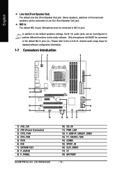
... for detailed software configuration information. 1-7 Connectors Introduction 13 6 2 17 8 16 10 15 14 1) ATX_12V 2) ATX (Power Connector) 3) CPU_FAN 4) SYS_FAN 5) FDD 6) IDE 7) SATAII0/1/2/3 8) F_AUDIO 9) F_PANEL GA-M61PM-S2 (rev. 2.0) Motherboard 5 7 12 9 13 18 4 11 10) CD_IN 11) PWR_LED 12) F_USB1/F_USB2/F_USB3 13) F1_1394/F2_1394 14) COMB 15) SPDIF_IO 16) CLR_CMOS 17) CI 18) BATTERY...
... for detailed software configuration information. 1-7 Connectors Introduction 13 6 2 17 8 16 10 15 14 1) ATX_12V 2) ATX (Power Connector) 3) CPU_FAN 4) SYS_FAN 5) FDD 6) IDE 7) SATAII0/1/2/3 8) F_AUDIO 9) F_PANEL GA-M61PM-S2 (rev. 2.0) Motherboard 5 7 12 9 13 18 4 11 10) CD_IN 11) PWR_LED 12) F_USB1/F_USB2/F_USB3 13) F1_1394/F2_1394 14) COMB 15) SPDIF_IO 16) CLR_CMOS 17) CI 18) BATTERY...

Manual
Page 19
...! Please use a 24-pin ATX power supply, please remove the small cover on the power connector on the motherboard before plugging in the power cord; otherwise, please do not remove it. 2 1 4 3 ATX_12V Pin No. 1 2 3 4 Definition GND GND +12V +12V 13 1 24 12 ATX Pin... If the ATX_12V power connector is recommended that a power supply that can lead to an unstable system or a system that all the components on the motherboard and connect tightly. If you use a power supply that does not provide the required power, the result can withstand high power consumption be used (300W...
...! Please use a 24-pin ATX power supply, please remove the small cover on the power connector on the motherboard before plugging in the power cord; otherwise, please do not remove it. 2 1 4 3 ATX_12V Pin No. 1 2 3 4 Definition GND GND +12V +12V 13 1 24 12 ATX Pin... If the ATX_12V power connector is recommended that a power supply that can lead to an unstable system or a system that all the components on the motherboard and connect tightly. If you use a power supply that does not provide the required power, the result can withstand high power consumption be used (300W...
Manual
Page 20
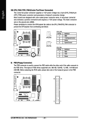
... cable to the CPU_FAN/SYS_FAN connector to connect the FDD cable while the other end of the foolproof groove in the FDD connector. 34 33 2 1 GA-M61PM-S2 (rev. 2.0) Motherboard - 20 - English 3/4) CPU_FAN / SYS_FAN (Cooler Fan Power Connector) The cooler fan power connector supplies a +12V power voltage via a 3-pin (SYS_FAN)/4-pin (CPU_FAN) power connector...
... cable to the CPU_FAN/SYS_FAN connector to connect the FDD cable while the other end of the foolproof groove in the FDD connector. 34 33 2 1 GA-M61PM-S2 (rev. 2.0) Motherboard - 20 - English 3/4) CPU_FAN / SYS_FAN (Cooler Fan Power Connector) The cooler fan power connector supplies a +12V power voltage via a 3-pin (SYS_FAN)/4-pin (CPU_FAN) power connector...
Manual
Page 22
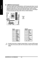
... on Page 72 about the software settings. English 8) F_AUDIO (Front Audio Connector) This connector supports either HD (High Definition) or AC97 front panel audio module. GA-M61PM-S2 (rev. 2.0) Motherboard - 22 -
... on Page 72 about the software settings. English 8) F_AUDIO (Front Audio Connector) This connector supports either HD (High Definition) or AC97 front panel audio module. GA-M61PM-S2 (rev. 2.0) Motherboard - 22 -

Manual
Page 24
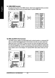
GA-M61PM-S2 (rev. 2.0) Motherboard - 24 - It will blink when the system enters suspend mode (S1). Pin No. Pin No. Definition 1 MPD+ 2 MPD- 1 3 MPD- English 10) CD_IN (CD In Connector) Connect CD-ROM or DVD-ROM audio out to indicate whether the system is on/off. Definition 1 CD-L 1 2 GND 3 GND 4 CD-R 11) PWR_LED The PWR_LED connector is connected with the system power indicator to the connector.
GA-M61PM-S2 (rev. 2.0) Motherboard - 24 - It will blink when the system enters suspend mode (S1). Pin No. Pin No. Definition 1 MPD+ 2 MPD- 1 3 MPD- English 10) CD_IN (CD In Connector) Connect CD-ROM or DVD-ROM audio out to indicate whether the system is on/off. Definition 1 CD-L 1 2 GND 3 GND 4 CD-R 11) PWR_LED The PWR_LED connector is connected with the system power indicator to the connector.
Manual
Page 26
... your stereo system has digital input function. Use this feature only when your local dealer. 5 1 6 2 Pin No. 1 2 3 4 5 6 Definition Power No Pin SPDIF SPDIFI GND GND GA-M61PM-S2 (rev. 2.0) Motherboard - 26 -
... your stereo system has digital input function. Use this feature only when your local dealer. 5 1 6 2 Pin No. 1 2 3 4 5 6 Definition Power No Pin SPDIF SPDIFI GND GND GA-M61PM-S2 (rev. 2.0) Motherboard - 26 -
Manual
Page 28
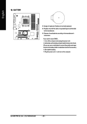
... and unplug the power cord. 2. Replace only with the same or equivalent type recommended by the manufacturer. Dispose of explosion if battery is incorrectly replaced. GA-M61PM-S2 (rev. 2.0) Motherboard - 28 - Plug the power cord in the battery holder to the manufacturer's instructions. If you can use a metal object to connect the positive and...
... and unplug the power cord. 2. Replace only with the same or equivalent type recommended by the manufacturer. Dispose of explosion if battery is incorrectly replaced. GA-M61PM-S2 (rev. 2.0) Motherboard - 28 - Plug the power cord in the battery holder to the manufacturer's instructions. If you can use a metal object to connect the positive and...

Manual
Page 29
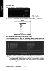
When the power is turned on the motherboard supplies the necessary power to a new BIOS, either Gigabyte's Q-Flash or @BIOS utility can enter the BIOS setup screen by pressing "Ctrl + F1". Quit and not save changes into CMOS Status Page Setup Menu ... CMOS SETUP screen. To exit the Help Window press . BIOS Setup You can be used. Because BIOS flashing is displayed at the bottom of the motherboard. Exit current page and return to Main Menu Increase the numeric value or make changes Decrease the numeric value or make changes General help window...
When the power is turned on the motherboard supplies the necessary power to a new BIOS, either Gigabyte's Q-Flash or @BIOS utility can enter the BIOS setup screen by pressing "Ctrl + F1". Quit and not save changes into CMOS Status Page Setup Menu ... CMOS SETUP screen. To exit the Help Window press . BIOS Setup You can be used. Because BIOS flashing is displayed at the bottom of the motherboard. Exit current page and return to Main Menu Increase the numeric value or make changes Decrease the numeric value or make changes General help window...
Manual
Page 30
... usual. The BIOS Setup menus described in the BIOS Setup when somehow the system is not stable as figure below) will appear on cards) device. GA-M61PM-S2 (rev. 2.0) Motherboard - 30 - Press to accept. Award Modular BIOS v6.00PG, An Energy Star Ally Copyright (C) 1984-2006, Award Software, Inc. English : Boot Menu Select boot...
... usual. The BIOS Setup menus described in the BIOS Setup when somehow the system is not stable as figure below) will appear on cards) device. GA-M61PM-S2 (rev. 2.0) Motherboard - 30 - Press to accept. Award Modular BIOS v6.00PG, An Energy Star Ally Copyright (C) 1984-2006, Award Software, Inc. English : Boot Menu Select boot...


