Manual
Page 4
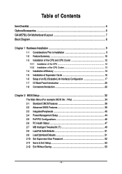
Table of Contents ItemChecklist ...6 OptionalAccessories ...6 GA-M57SLI-S4 Motherboard Layout 7 Block Diagram ...8 Chapter 1 Hardware Installation 9 1-1 Considerations Prior to Installation 9 1-2 Feature Summary 10 1-3 Installation of the ...SLI (Scalable Link Interface) Configuration 17 1-7 I/O Back Panel Introduction 20 1-8 Connectors Introduction 22 Chapter 2 BIOS Setup 33 The Main Menu (For example: BIOS Ver. : FAa 34 2-1 Standard CMOS Features 36 2-2 Advanced BIOS Features 38 2-3 IntegratedPeripherals 40 2-4 Power Management Setup 44 2-5 PnP/PCI Configurations 46 2-6 PC Health ...
Table of Contents ItemChecklist ...6 OptionalAccessories ...6 GA-M57SLI-S4 Motherboard Layout 7 Block Diagram ...8 Chapter 1 Hardware Installation 9 1-1 Considerations Prior to Installation 9 1-2 Feature Summary 10 1-3 Installation of the ...SLI (Scalable Link Interface) Configuration 17 1-7 I/O Back Panel Introduction 20 1-8 Connectors Introduction 22 Chapter 2 BIOS Setup 33 The Main Menu (For example: BIOS Ver. : FAa 34 2-1 Standard CMOS Features 36 2-2 Advanced BIOS Features 38 2-3 IntegratedPeripherals 40 2-4 Power Management Setup 44 2-5 PnP/PCI Configurations 46 2-6 PC Health ...

Manual
Page 5
Chapter 3 Drivers Installation 55 3-1 Install Chipset Drivers 55 3-2 SoftwareApplications 56 3-3 Driver CD Information 56 3-4 Hardware Information 57 3-5 Contact Us ...57 Chapter 4 Appendix 59 4-1 Unique Software Utilities 59 4-1-1 EasyTune 5 Introduction 59 4-1-2 Xpress Recovery2 Introduction 60 4-1-3 Flash BIOS Method Introduction 62 4-1-4 Configuring SATA Hard Drive(s 66 4-1-5 2- / 4- / 6- / 8- Channel Audio Function Introduction 76 4-2 Troubleshooting 81 - 5 -
Chapter 3 Drivers Installation 55 3-1 Install Chipset Drivers 55 3-2 SoftwareApplications 56 3-3 Driver CD Information 56 3-4 Hardware Information 57 3-5 Contact Us ...57 Chapter 4 Appendix 59 4-1 Unique Software Utilities 59 4-1-1 EasyTune 5 Introduction 59 4-1-2 Xpress Recovery2 Introduction 60 4-1-3 Flash BIOS Method Introduction 62 4-1-4 Configuring SATA Hard Drive(s 66 4-1-5 2- / 4- / 6- / 8- Channel Audio Function Introduction 76 4-2 Troubleshooting 81 - 5 -
Manual
Page 8
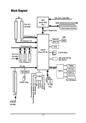
Block Diagram SLI PCIe CLK (100 MHz) AMD Socket AM2 CPU CPU CLK+/-(200 MHz) DDRII 800/667/533/400 MHz DIMM Hyper Transport Bus Dual Channel Memory PCI Express x8 PCI Express x16 Marvell 88E1116 LAN RJ45 PCI Express Bus x1 x1 x1 PCIe CLK (100 MHz) 3 PCI Express x1 PCI Bus TSB43AB23 3 IEEE 1394a nVIDIA® nForce 570-SLI BIOS 6 SATA 3Gb/s ATA-33/66/100/133 IDE Channel CODEC LPC BUS IT8716 Floppy LPT Port COM Port 10 USB Ports PS/2 KB/Mouse Surround Speaker Out Center/Subwoofer Speaker Out Side Speaker Out MIC Line-Out Line-In SPDIF In SPDIF Out 2 PCI PCI CLK (33 MHz) - 8 -
Block Diagram SLI PCIe CLK (100 MHz) AMD Socket AM2 CPU CPU CLK+/-(200 MHz) DDRII 800/667/533/400 MHz DIMM Hyper Transport Bus Dual Channel Memory PCI Express x8 PCI Express x16 Marvell 88E1116 LAN RJ45 PCI Express Bus x1 x1 x1 PCIe CLK (100 MHz) 3 PCI Express x1 PCI Bus TSB43AB23 3 IEEE 1394a nVIDIA® nForce 570-SLI BIOS 6 SATA 3Gb/s ATA-33/66/100/133 IDE Channel CODEC LPC BUS IT8716 Floppy LPT Port COM Port 10 USB Ports PS/2 KB/Mouse Surround Speaker Out Center/Subwoofer Speaker Out Side Speaker Out MIC Line-Out Line-In SPDIF In SPDIF Out 2 PCI PCI CLK (33 MHz) - 8 -
Manual
Page 11
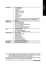
.../ System fan failure warning Š Supports CPU Smart Fan function (Note 2) BIOS Š 1 4 Mbit flash ROM Š Use of licensed AWARD BIOS Š PnP 1.0a, DMI 2.0, SM BIOS 2.3, ACPI 1.0b Additional Features Š Supports @BIOS Š Supports Download Center Š Supports Q-Flash Š Supports EasyTune (Note... 3) Š Supports Xpress Install Š Supports Xpress Recovery2 Š Supports Xpress BIOS Rescue Bundle Software Š Norton Internet Security (OEM version) Form Factor Š ATX form factor; 30.5cm x 23.4cm...
.../ System fan failure warning Š Supports CPU Smart Fan function (Note 2) BIOS Š 1 4 Mbit flash ROM Š Use of licensed AWARD BIOS Š PnP 1.0a, DMI 2.0, SM BIOS 2.3, ACPI 1.0b Additional Features Š Supports @BIOS Š Supports Download Center Š Supports Q-Flash Š Supports EasyTune (Note... 3) Š Supports Xpress Install Š Supports Xpress Recovery2 Š Supports Xpress BIOS Rescue Bundle Software Š Norton Internet Security (OEM version) Form Factor Š ATX form factor; 30.5cm x 23.4cm...

Manual
Page 14
A memory module can be installed in one direction. The motherboard supports DDRII memory modules, whereby BIOS will automatically detect memory capacity and specifications. Reverse the installation steps when you are designed so that the memory used is switched ... they can be used can only fit in only one direction. Memory modules are unable to remove the DIMM module. The memory capacity used . 2. GA-M57SLI-S4 Motherboard - 14 - Memory modules have a foolproof insertion design. It is recommended that the computer power is supported by the motherboard. Insert the DIMM ...
A memory module can be installed in one direction. The motherboard supports DDRII memory modules, whereby BIOS will automatically detect memory capacity and specifications. Reverse the installation steps when you are designed so that the memory used is switched ... they can be used can only fit in only one direction. Memory modules are unable to remove the DIMM module. The memory capacity used . 2. GA-M57SLI-S4 Motherboard - 14 - Memory modules have a foolproof insertion design. It is recommended that the computer power is supported by the motherboard. Insert the DIMM ...

Manual
Page 16
...the PCI Express x16 slot and press down on the computer, if necessary, configure required settings for the expansion card in system BIOS Setup. 8. The motherboard includes a PCIE_12V power connector, which provides extra power to secure the slot bracket of the PCI ...read the expansion card's installation manual before installing the expansion card in the slot. 5. Remove your expansion card, follow the steps below. 1. GA-M57SLI-S4 Motherboard - 16 - English 1-5 Installation of the drawable bar as the picture to uninstall the VGA card. Disconnect your computer's chassis cover....
...the PCI Express x16 slot and press down on the computer, if necessary, configure required settings for the expansion card in system BIOS Setup. 8. The motherboard includes a PCIE_12V power connector, which provides extra power to secure the slot bracket of the PCI ...read the expansion card's installation manual before installing the expansion card in the slot. 5. Remove your expansion card, follow the steps below. 1. GA-M57SLI-S4 Motherboard - 16 - English 1-5 Installation of the drawable bar as the picture to uninstall the VGA card. Disconnect your computer's chassis cover....
Manual
Page 26
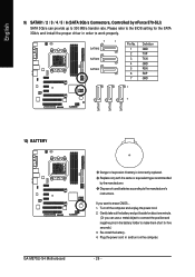
... work properly. 7 1 SATAII6 SATAII5 SATAII4 Pin No. 1 2 3 4 5 6 7 Definition GND TXP TXN GND RXN RXP GND 1 7 10) BATTERY GA-M57SLI-S4 Motherboard Danger of used batteries according to 300 MB/s transfer rate. Please refer to the BIOS setting for about one minute. (Or you want to make them short for five seconds.) 3. Replace only with...
... work properly. 7 1 SATAII6 SATAII5 SATAII4 Pin No. 1 2 3 4 5 6 7 Definition GND TXP TXN GND RXN RXP GND 1 7 10) BATTERY GA-M57SLI-S4 Motherboard Danger of used batteries according to 300 MB/s transfer rate. Please refer to the BIOS setting for about one minute. (Or you want to make them short for five seconds.) 3. Replace only with...

Manual
Page 31
Hardware Installation You can check the "Case Opened" status in BIOS Setup. Open: Normal Short: Clear CMOS - 31 - English 18) CI (Chassis Intrusion, Case Open) This 2-pin connector allows your system to avoid improper use of this header. Definition 1 Signal 1 2 GND 19) CLR_CMOS (Clear CMOS) You may clear the CMOS data to its default values by this header. To clear CMOS, temporarily short the two pins. Pin No. Default doesn't include the jumper to detect if the chassis cover is removed.
Hardware Installation You can check the "Case Opened" status in BIOS Setup. Open: Normal Short: Clear CMOS - 31 - English 18) CI (Chassis Intrusion, Case Open) This 2-pin connector allows your system to avoid improper use of this header. Definition 1 Signal 1 2 GND 19) CLR_CMOS (Clear CMOS) You may clear the CMOS data to its default values by this header. To clear CMOS, temporarily short the two pins. Pin No. Default doesn't include the jumper to detect if the chassis cover is removed.

Manual
Page 33
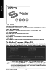
... off, the battery on , pressing the button during the BIOS POST (Power-On Self Test) will take you wish to upgrade to the CMOS SETUP screen. If you to a new BIOS, either Gigabyte's Q-Flash or @BIOS utility can enter the BIOS setup screen by pressing "Ctrl + F1". Q-Flash allows ...the user to quickly and easily update or backup BIOS without entering the operating system. @BIOS is potentially risky, please do it with caution ...
... off, the battery on , pressing the button during the BIOS POST (Power-On Self Test) will take you wish to upgrade to the CMOS SETUP screen. If you to a new BIOS, either Gigabyte's Q-Flash or @BIOS utility can enter the BIOS setup screen by pressing "Ctrl + F1". Q-Flash allows ...the user to quickly and easily update or backup BIOS without entering the operating system. @BIOS is potentially risky, please do it with caution ...
Manual
Page 34
...figure below) will appear on page 39.) : BIOS Setup/Q-Flash Press the Delete key to enter BIOS Setup or to access the Q-Flash utility in this chapter are for reference only and may differ from BIOS Time, Date, Hard Disk Type... 1. GA-M57SLI-S4 Motherboard - 34 - Use arrow keys to ...select among the items and press to access advanced options. 2. The BIOS Setup menus described in BIOS Setup. : Xpress Recovery2 Press the F9 key to enter...
...figure below) will appear on page 39.) : BIOS Setup/Q-Flash Press the Delete key to enter BIOS Setup or to access the Q-Flash utility in this chapter are for reference only and may differ from BIOS Time, Date, Hard Disk Type... 1. GA-M57SLI-S4 Motherboard - 34 - Use arrow keys to ...select among the items and press to access advanced options. 2. The BIOS Setup menus described in BIOS Setup. : Xpress Recovery2 Press the F9 key to enter...

Manual
Page 35
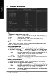
.... „ Load Optimized Defaults Optimized Defaults indicates the value of the system parameters which the system would be in standard compatible BIOS. „ Advanced BIOS Features This setup page includes all the items of Award special enhanced features. „ Integrated Peripherals This setup page includes all...best performance configuration. „ Set Supervisor Password Change, set , or disable password. F12 : Load CMOS from BIOS If your system becomes unstable and you load the default BIOS settings, you to limit access to the system. „ Save & Exit Setup Save CMOS value settings to...
.... „ Load Optimized Defaults Optimized Defaults indicates the value of the system parameters which the system would be in standard compatible BIOS. „ Advanced BIOS Features This setup page includes all the items of Award special enhanced features. „ Integrated Peripherals This setup page includes all...best performance configuration. „ Set Supervisor Password Change, set , or disable password. F12 : Load CMOS from BIOS If your system becomes unstable and you load the default BIOS settings, you to limit access to the system. „ Save & Exit Setup Save CMOS value settings to...
Manual
Page 36
...to select this option for faster system start up. • Manual User can use one of the three methods: • Auto Allows BIOS to set the access mode for faster system start up. The time is 13:0:0. is calculated based on the 24-hour military-time clock...through 2099 Time The times format in . Through Dec. IDE Channel 0 Master/Slave devices setup. The four options are : Large/Auto(default:Auto) GA-M57SLI-S4 Motherboard - 36 - The two options are : CHS/LBA/Large/Auto(default:Auto) IDE Channel 2/3/4/5/6/7 Master IDE HDD Auto-Detection Press "Enter" to ...
...to select this option for faster system start up. • Manual User can use one of the three methods: • Auto Allows BIOS to set the access mode for faster system start up. The time is 13:0:0. is calculated based on the 24-hour military-time clock...through 2099 Time The times format in . Through Dec. IDE Channel 0 Master/Slave devices setup. The four options are : Large/Auto(default:Auto) GA-M57SLI-S4 Motherboard - 36 - The two options are : CHS/LBA/Large/Auto(default:Auto) IDE Channel 2/3/4/5/6/7 Master IDE HDD Auto-Detection Press "Enter" to ...

Manual
Page 37
...POST of base (or conventional) memory installed in the computer. Halt on The category determines whether the computer will determine the amount of the BIOS will stop for all other errors. (Default value) All, But Diskette The system boot will stop if an error is present during power ...up. it will stop for all other errors. Extended Memory The BIOS determines how much extended memory is detected during the POST. None No floppy drive installed. 360K, 5.25" 5.25 inch PC-type standard ...
...POST of base (or conventional) memory installed in the computer. Halt on The category determines whether the computer will determine the amount of the BIOS will stop for all other errors. (Default value) All, But Diskette The system boot will stop if an error is present during power ...up. it will stop for all other errors. Extended Memory The BIOS determines how much extended memory is detected during the POST. None No floppy drive installed. 360K, 5.25" 5.25 inch PC-type standard ...

Manual
Page 38
...Priority Select boot sequence for onboard(or add-on cards) SCSI, RAID, etc. ZIP USB-FDD Select your boot device priority by ZIP. GA-M57SLI-S4 Motherboard - 38 - Hard Disk CDROM Select your boot device priority by Hard Disk. Select your boot device priority by USB-FDD. USB...-ZIP Select your boot device priority by USB-ZIP. English 2-2 Advanced BIOS Features CMOS Setup Utility-Copyright (C) 1984-2007 Award Software Advanced BIOS Features AMD K8 Cool&Quiet control Hard Disk Boot Priority First Boot Device Second Boot Device Third Boot ...
...Priority Select boot sequence for onboard(or add-on cards) SCSI, RAID, etc. ZIP USB-FDD Select your boot device priority by ZIP. GA-M57SLI-S4 Motherboard - 38 - Hard Disk CDROM Select your boot device priority by Hard Disk. Select your boot device priority by USB-FDD. USB...-ZIP Select your boot device priority by USB-ZIP. English 2-2 Advanced BIOS Features CMOS Setup Utility-Copyright (C) 1984-2007 Award Software Advanced BIOS Features AMD K8 Cool&Quiet control Hard Disk Boot Priority First Boot Device Second Boot Device Third Boot ...

Manual
Page 39
... tasks while in a low-power mode that appears off.) Full Screen LOGO Show Enabled Show full screen logo at the prompt. (Default value) HDD S.M.A.R.T. Enabled BIOS searches for the type of the monitor display from 720 KB, 1.2 MB or 1.44 MB drive type as they are all 80 tracks. If you.... (Default value) Disabled Disable this item to select the first initiation of floppy disk drive by track number. English Boot Up Floppy Seek During POST, BIOS will determine the floppy disk drive installed is 40 or 80 tracks. 360 KB type is 40 tracks, 720 KB, 1.2 MB and 1.44 MB are...
... tasks while in a low-power mode that appears off.) Full Screen LOGO Show Enabled Show full screen logo at the prompt. (Default value) HDD S.M.A.R.T. Enabled BIOS searches for the type of the monitor display from 720 KB, 1.2 MB or 1.44 MB drive type as they are all 80 tracks. If you.... (Default value) Disabled Disable this item to select the first initiation of floppy disk drive by track number. English Boot Up Floppy Seek During POST, BIOS will determine the floppy disk drive installed is 40 or 80 tracks. 360 KB type is 40 tracks, 720 KB, 1.2 MB and 1.44 MB are...

Manual
Page 41
... value) Disabled Disable the RAID function of this channel. SATA-1+2 Enable the first and the second SATA controller. All Enabled Enable all the 3 SATA controllers. BIOS Setup It will operate in core chipset. (Default value) NV Serial-ATA Controller Disabled Disable all the 3 SATA controllers. (Default value) IDE Prefetch Mode Enabled...
... value) Disabled Disable the RAID function of this channel. SATA-1+2 Enable the first and the second SATA controller. All Enabled Enable all the 3 SATA controllers. BIOS Setup It will operate in core chipset. (Default value) NV Serial-ATA Controller Disabled Disable all the 3 SATA controllers. (Default value) IDE Prefetch Mode Enabled...

Manual
Page 42
... Enhanced Parallel Port. Disabled Disable onboard Serial port 1. Enabled Disabled Enable this function. (Default value) Onboard Serial Port 1 Auto BIOS will show Short or Open, and the length shown is detected on the LAN cable connected to the motherboard, the Status fields ... show N/A, as Extended Capabilities Port. If no LAN cable is 3E8/IRQ4. When a Cable Problem Occurs... If a cable problem occurs on Pair 1-2. GA-M57SLI-S4 Motherboard - 42 - When No LAN Cable Is Attached... Disable this function. For example, if it shows Pair1-2 Status = Short / Length = 1.6m...
... Enhanced Parallel Port. Disabled Disable onboard Serial port 1. Enabled Disabled Enable this function. (Default value) Onboard Serial Port 1 Auto BIOS will show Short or Open, and the length shown is detected on the LAN cable connected to the motherboard, the Status fields ... show N/A, as Extended Capabilities Port. If no LAN cable is 3E8/IRQ4. When a Cable Problem Occurs... If a cable problem occurs on Pair 1-2. GA-M57SLI-S4 Motherboard - 42 - When No LAN Cable Is Attached... Disable this function. For example, if it shows Pair1-2 Status = Short / Length = 1.6m...

Manual
Page 43
... mouse support. English ECP Mode Use DMA This item will scan all USB storage devices. (Default value) Disabled Disable this function. - 43 - BIOS Setup USB Keyboard Support Enabled Disabled Enable USB keyboard support. On-Chip USB V1.1+V2.0 V1.1 Enable USB 1.1 and USB 2.0 controllers. (Default ...onchip USB support. Disabled Disable USB mouse support. (Default value) Legacy USB storage detect This option allows users to decide whether to 1. Enabled BIOS will become available when Parallel Port Mode set to ECP or ECP+EPP. 3 Set ECP Mode Use DMA to 3. (Default value) 1...
... mouse support. English ECP Mode Use DMA This item will scan all USB storage devices. (Default value) Disabled Disable this function. - 43 - BIOS Setup USB Keyboard Support Enabled Disabled Enable USB keyboard support. On-Chip USB V1.1+V2.0 V1.1 Enable USB 1.1 and USB 2.0 controllers. (Default ...onchip USB support. Disabled Disable USB mouse support. (Default value) Legacy USB storage detect This option allows users to decide whether to 1. Enabled BIOS will become available when Parallel Port Mode set to ECP or ECP+EPP. 3 Set ECP Mode Use DMA to 3. (Default value) 1...

Manual
Page 45
...) Double-Click Double click on PS/2 mouse left button to power on the system. KB Power ON Password When "Power On by Keyboard" is Enabled. BIOS Setup Keyboard 98 If your keyboard have "POWER Key" button, you can set "Power-On by Alarm" item to set the Keyboard Power On password...
...) Double-Click Double click on PS/2 mouse left button to power on the system. KB Power ON Password When "Power On by Keyboard" is Enabled. BIOS Setup Keyboard 98 If your keyboard have "POWER Key" button, you can set "Power-On by Alarm" item to set the Keyboard Power On password...

Manual
Page 47
... 1.8V / +3.3V / +12V Detect system's voltage status automatically. Case Opened If the case is opened, Case Opened will restart. Monitor CPU temperature at next boot. BIOS Setup
... 1.8V / +3.3V / +12V Detect system's voltage status automatically. Case Opened If the case is opened, Case Opened will restart. Monitor CPU temperature at next boot. BIOS Setup


