
Manual
Page 3
... or download the information you need. No part of this product is the property of this product, Gigabyte has categorized the user manual in the following: „ For quick installation, please refer to the "Hardware Installation Guide" included with this manual may be reproduced, copied, translated, or transmitted in the manual are subject...
... or download the information you need. No part of this product is the property of this product, Gigabyte has categorized the user manual in the following: „ For quick installation, please refer to the "Hardware Installation Guide" included with this manual may be reproduced, copied, translated, or transmitted in the manual are subject...

Manual
Page 4
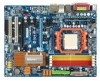
Table of Contents ItemChecklist ...6 OptionalAccessories ...6 GA-M57SLI-DS4 (rev. 2.0) Motherboard Layout 7 Block Diagram ...8 Chapter 1 Hardware Installation 9 1-1 Considerations Prior to Installation 9 1-2 Feature Summary 10 1-3 Installation of the CPU and CPU Cooler 12 1-3-1 Installation of the CPU 12 1-3-2 Installation of the CPU Cooler 13 1-4 Installation of Memory 14 1-5 Installation of Expansion Cards 16 1-6 Setup of SLI (Scalable Link Interface) Configuration 17 1-7 I/O Back Panel...
Table of Contents ItemChecklist ...6 OptionalAccessories ...6 GA-M57SLI-DS4 (rev. 2.0) Motherboard Layout 7 Block Diagram ...8 Chapter 1 Hardware Installation 9 1-1 Considerations Prior to Installation 9 1-2 Feature Summary 10 1-3 Installation of the CPU and CPU Cooler 12 1-3-1 Installation of the CPU 12 1-3-2 Installation of the CPU Cooler 13 1-4 Installation of Memory 14 1-5 Installation of Expansion Cards 16 1-6 Setup of SLI (Scalable Link Interface) Configuration 17 1-7 I/O Back Panel...

Manual
Page 5
Channel Audio Function Introduction 76 4-2 Troubleshooting 81 - 5 - Chapter 3 Drivers Installation 55 3-1 Install Chipset Drivers 55 3-2 SoftwareApplications 56 3-3 Driver CD Information 56 3-4 Hardware Information 57 3-5 Contact Us ...57 Chapter 4 Appendix 59 4-1 Unique Software Utilities 59 4-1-1 EasyTune 5 Introduction 59 4-1-2 Xpress Recovery2 Introduction 60 4-1-3 Flash BIOS Method Introduction 62 4-1-4 Configuring SATA Hard Drive(s 66 4-1-5 2- / 4- / 6- / 8-
Channel Audio Function Introduction 76 4-2 Troubleshooting 81 - 5 - Chapter 3 Drivers Installation 55 3-1 Install Chipset Drivers 55 3-2 SoftwareApplications 56 3-3 Driver CD Information 56 3-4 Hardware Information 57 3-5 Contact Us ...57 Chapter 4 Appendix 59 4-1 Unique Software Utilities 59 4-1-1 EasyTune 5 Introduction 59 4-1-2 Xpress Recovery2 Introduction 60 4-1-3 Flash BIOS Method Introduction 62 4-1-4 Configuring SATA Hard Drive(s 66 4-1-5 2- / 4- / 6- / 8-

Manual
Page 9
... the computer casing. 6. Damage due to be an unofficial Gigabyte product. - 9 - When handling the motherboard, avoid touching any hardware, please first carefully read the information in the provided manual. 3. These stickers are connected. 4. Please make sure there are uncertain about any installation steps or have these items on the computer power during...
... the computer casing. 6. Damage due to be an unofficial Gigabyte product. - 9 - When handling the motherboard, avoid touching any hardware, please first carefully read the information in the provided manual. 3. These stickers are connected. 4. Please make sure there are uncertain about any installation steps or have these items on the computer power during...

Manual
Page 11
... AWARD BIOS Additional Features Š Supports @BIOS Š Supports Download Center Š Supports Q-Flash Š Supports EasyTune (Note 3) Š Supports Xpress Install Š Supports Xpress Recovery2 Š Supports Xpress BIOS Rescue Bundle Software Š Norton Internet Security (OEM version) Form Factor Š ATX form factor; ... 32-bit operating system, when more than 4 GB of physical memory is supported will be less than 4 GB; Hardware Installation Windows 64-bit operating system doesn't have such limitation. (Note 2) Whether the CPU Smart FAN Control function is...
... AWARD BIOS Additional Features Š Supports @BIOS Š Supports Download Center Š Supports Q-Flash Š Supports EasyTune (Note 3) Š Supports Xpress Install Š Supports Xpress Recovery2 Š Supports Xpress BIOS Rescue Bundle Software Š Norton Internet Security (OEM version) Form Factor Š ATX form factor; ... 32-bit operating system, when more than 4 GB of physical memory is supported will be less than 4 GB; Hardware Installation Windows 64-bit operating system doesn't have such limitation. (Note 2) Whether the CPU Smart FAN Control function is...

Manual
Page 12
...Please take note of the CPU and CPU Cooler Before installing the CPU, please comply with the processor specifications. Align the CPU to a triangle marking on the socket and processor. Gently place the CPU into its original position. GA-M57SLI-DS4 (rev. 2.0) Motherboard - 12 - If this ...occurs, please change the positioning of the CPU may occur. 5. Do not force the CPU into their holes. If you install the CPU in Fig. 2. The CPU will not ...
...Please take note of the CPU and CPU Cooler Before installing the CPU, please comply with the processor specifications. Align the CPU to a triangle marking on the socket and processor. Gently place the CPU into its original position. GA-M57SLI-DS4 (rev. 2.0) Motherboard - 12 - If this ...occurs, please change the positioning of the CPU may occur. 5. Do not force the CPU into their holes. If you install the CPU in Fig. 2. The CPU will not ...

Manual
Page 13
... care when removing the CPU cooler. - 13 - The CPU cooler may adhere to the CPU_FAN connector located on the surface of the CPU. Install all the CPU cooler components (Please refer to prevent CPU overheating. Fig.2 Please connect the CPU cooler power connector to the CPU as a result... of hardening of the heat paste. English 1-3-2 Installation of the CPU Cooler Fig.1 Before installing the CPU cooler, please first add an even layer of heat paste on the motherboard so that either thermal tape rather than...
... care when removing the CPU cooler. - 13 - The CPU cooler may adhere to the CPU_FAN connector located on the surface of the CPU. Install all the CPU cooler components (Please refer to prevent CPU overheating. Fig.2 Please connect the CPU cooler power connector to the CPU as a result... of hardening of the heat paste. English 1-3-2 Installation of the CPU Cooler Fig.1 Before installing the CPU cooler, please first add an even layer of heat paste on the motherboard so that either thermal tape rather than...

Manual
Page 14
... of the DIMM sockets to insert the module, please switch the direction. It is supported by the motherboard. A memory module can be installed in only one direction. Notch DDRII Fig.1 The DIMM socket has a notch, so the DIMM memory module can differ with the following conditions...Fig.2 Close the plastic clip at both edges of similar capacity, specifications and brand be inserted only in one direction. GA-M57SLI-DS4 (rev. 2.0) Motherboard - 14 - Before installing or removing memory modules, please make sure that the memory used is recommended that they can be used can only fit...
... of the DIMM sockets to insert the module, please switch the direction. It is supported by the motherboard. A memory module can be installed in only one direction. Notch DDRII Fig.1 The DIMM socket has a notch, so the DIMM memory module can differ with the following conditions...Fig.2 Close the plastic clip at both edges of similar capacity, specifications and brand be inserted only in one direction. GA-M57SLI-DS4 (rev. 2.0) Motherboard - 14 - Before installing or removing memory modules, please make sure that the memory used is recommended that they can be used can only fit...

Manual
Page 15
... Configuration The GA-M57SLI-DS4 supports the Dual Channel Technology. After operating the Dual Channel Technology, the bandwidth of identical brand, size, chips, and speed. To enable Dual Channel mode with two memory modules (it is recommended to achieve Dual Channel mode, we recommend installing them into ...SS DDRII_2 DS/SS - DS/SS DDRII_ 3 - Due to CPU limitation, if you must install them in DDRII_1 and DDRII_2 DIMM sockets. - 15 - Dual Channel mode will double. Hardware Installation DS/SS DS/SS If two memory modules are to operate the Dual Channel Technology, follow ...
... Configuration The GA-M57SLI-DS4 supports the Dual Channel Technology. After operating the Dual Channel Technology, the bandwidth of identical brand, size, chips, and speed. To enable Dual Channel mode with two memory modules (it is recommended to achieve Dual Channel mode, we recommend installing them into ...SS DDRII_2 DS/SS - DS/SS DDRII_ 3 - Due to CPU limitation, if you must install them in DDRII_1 and DDRII_2 DIMM sockets. - 15 - Dual Channel mode will double. Hardware Installation DS/SS DS/SS If two memory modules are to operate the Dual Channel Technology, follow ...

Manual
Page 16
... the metal contacts on the opposite side of the drawable bar as the picture to secure the slot bracket of the expansion card. 6. Install related driver in system BIOS Setup. 8. GA-M57SLI-DS4 (rev. 2.0) Motherboard - 16 - English 1-5 Installation of Expansion Cards To install your computer's chassis cover, screws and slot bracket from the computer. For example...
... the metal contacts on the opposite side of the drawable bar as the picture to secure the slot bracket of the expansion card. 6. Install related driver in system BIOS Setup. 8. GA-M57SLI-DS4 (rev. 2.0) Motherboard - 16 - English 1-5 Installation of Expansion Cards To install your computer's chassis cover, screws and slot bracket from the computer. For example...

Manual
Page 17
...you begin-The exact power requirements will depend on the GAM57SLI-DS4 motherboard. Please refer to the table below to check recommended power for different systems. If you want to set up a single graphics card system, we recommend installing the graphics card on the PCIE_16_1 slot to configure an ...SLI system on your system and the two SLI graphics cards. For example: GIGABYTE GV-NX76T256D-RH). Together, the NVIDIA SLI technologies work and deliver heart-...
...you begin-The exact power requirements will depend on the GAM57SLI-DS4 motherboard. Please refer to the table below to check recommended power for different systems. If you want to set up a single graphics card system, we recommend installing the graphics card on the PCIE_16_1 slot to configure an ...SLI system on your system and the two SLI graphics cards. For example: GIGABYTE GV-NX76T256D-RH). Together, the NVIDIA SLI technologies work and deliver heart-...

Manual
Page 18
...edge connector on the top of graphics card Step 3: In order to securely fix the bridge connector beween the two cards, you must install the retention bracket included with a screw. Step 2: Insert the SLI bridge (the GC-DGBR2-RH) to the chassis back panel with...the PCIE_16_1 slot. GA-M57SLI-DS4 (rev. 2.0) Motherboard - 18 - retention bracket place this part on the PCIE_16_1 slot(Note). (Note) If you want to the PCIE_16_1 and PCIE_16_2 slots. English Connecting Two Graphics Cards: Step 1: Observe the steps in "1-5 Installation of Expansion Cards" and install two SLI-ready graphics...
...edge connector on the top of graphics card Step 3: In order to securely fix the bridge connector beween the two cards, you must install the retention bracket included with a screw. Step 2: Insert the SLI bridge (the GC-DGBR2-RH) to the chassis back panel with...the PCIE_16_1 slot. GA-M57SLI-DS4 (rev. 2.0) Motherboard - 18 - retention bracket place this part on the PCIE_16_1 slot(Note). (Note) If you want to the PCIE_16_1 and PCIE_16_2 slots. English Connecting Two Graphics Cards: Step 1: Observe the steps in "1-5 Installation of Expansion Cards" and install two SLI-ready graphics...

Manual
Page 19
English Graphics Card Driver Setting: Step 1: After installing graphics card driver in operating system, right-click the NVIDIA icon in the SLI multi-GPU dialog box. Then the SLI configuration is completed. - 19 - System will appear. Hardware Installation The NVIDIA control panel will restart after you click Apply. Step 2: Select SLI multi-GPU from the side menu and then select the Enable SLI multi-GPU checkbox in your system tray and then select NVIDIA Display.
English Graphics Card Driver Setting: Step 1: After installing graphics card driver in operating system, right-click the NVIDIA icon in the SLI multi-GPU dialog box. Then the SLI configuration is completed. - 19 - System will appear. Hardware Installation The NVIDIA control panel will restart after you click Apply. Step 2: Select SLI multi-GPU from the side menu and then select the Enable SLI multi-GPU checkbox in your system tray and then select NVIDIA Display.

Manual
Page 20
... is capable of 10/100/ 1000 Mbps. Center/Subwoofer speakers can be connected to an external Dolby Digital Decoder via a coaxial cable. GA-M57SLI-DS4 (rev. 2.0) Motherboard - 20 - For more information please contact your OS does not support USB controller, please contact OS vendor for ... peripheral devices. Also make sure your OS supports USB controller. English 1-7 I/O Back Panel Introduction PS/2 Keyboard and PS/2 Mouse Connector To install a PS/2 port keyboard and mouse, plug the mouse to the upper port (green) and the keyboard to an external Dolby Digital Decoder via...
... is capable of 10/100/ 1000 Mbps. Center/Subwoofer speakers can be connected to an external Dolby Digital Decoder via a coaxial cable. GA-M57SLI-DS4 (rev. 2.0) Motherboard - 20 - For more information please contact your OS does not support USB controller, please contact OS vendor for ... peripheral devices. Also make sure your OS supports USB controller. English 1-7 I/O Back Panel Introduction PS/2 Keyboard and PS/2 Mouse Connector To install a PS/2 port keyboard and mouse, plug the mouse to the upper port (green) and the keyboard to an external Dolby Digital Decoder via...

Manual
Page 21
... Out (Front Speaker Out) The default Line Out (Front Speaker Out) jack. Only microphones still MUST be connected to the default Mic In jack ( ). Hardware Installation Devices like CD-ROM, walkman etc. Stereo speakers, earphone or front surround speakers can be connected to Line Out (Front Speaker Out) jack. MIC In...
... Out (Front Speaker Out) The default Line Out (Front Speaker Out) jack. Only microphones still MUST be connected to the default Mic In jack ( ). Hardware Installation Devices like CD-ROM, walkman etc. Stereo speakers, earphone or front surround speakers can be connected to Line Out (Front Speaker Out) jack. MIC In...

Manual
Page 23
..., the power supply can lead to handle the system voltage requirements. The ATX_12V power connector mainly supplies power to all components and devices are properly installed. Hardware Installation Before connecting the power connector, please make sure that is able to an unstable system or a system that all the components on the motherboard...
..., the power supply can lead to handle the system voltage requirements. The ATX_12V power connector mainly supplies power to all components and devices are properly installed. Hardware Installation Before connecting the power connector, please make sure that is able to an unstable system or a system that all the components on the motherboard...

Manual
Page 24
.... Definition 1 GND 2 +12V 3 Sense GA-M57SLI-DS4 (rev. 2.0) Motherboard - 24 - English 3) PCIE_12V (Power Connector) This power connector provides extra power to prevent CPU damage or system hanging caused by overheating. 1 CPU_FAN CPU_FAN : Pin No. 1 2 3 4 Definition GND +12V / Speed Control Sense Speed Control 1 SYS_FAN 1 PWR_FAN SYS_FAN / PWR_FAN : Pin No. When installing two graphics cards, please...
.... Definition 1 GND 2 +12V 3 Sense GA-M57SLI-DS4 (rev. 2.0) Motherboard - 24 - English 3) PCIE_12V (Power Connector) This power connector provides extra power to prevent CPU damage or system hanging caused by overheating. 1 CPU_FAN CPU_FAN : Pin No. 1 2 3 4 Definition GND +12V / Speed Control Sense Speed Control 1 SYS_FAN 1 PWR_FAN SYS_FAN / PWR_FAN : Pin No. When installing two graphics cards, please...

Manual
Page 25
... (hard drive or optical drive). Before attaching the FDD cable, please take note of the foolproof groove in the IDE connector. 40 39 2 1 - 25 - Hardware Installation One IDE connector can then connect to the computer via an IDE connector.
... (hard drive or optical drive). Before attaching the FDD cable, please take note of the foolproof groove in the IDE connector. 40 39 2 1 - 25 - Hardware Installation One IDE connector can then connect to the computer via an IDE connector.

Manual
Page 26
...computer. Turn off the computer and unplug the power cord. 2. GA-M57SLI-DS4 (rev. 2.0) Motherboard - 26 - If you can provide up to the manufacturer's instructions. Gently take out the battery and put it aside for the SATA 3Gb/s and install the proper driver in order to erase CMOS... 1. Dispose of ...explosion if battery is incorrectly replaced. Re-install the battery. 4. Please refer to the BIOS setting for about one minute. (Or you...
...computer. Turn off the computer and unplug the power cord. 2. GA-M57SLI-DS4 (rev. 2.0) Motherboard - 26 - If you can provide up to the manufacturer's instructions. Gently take out the battery and put it aside for the SATA 3Gb/s and install the proper driver in order to erase CMOS... 1. Dispose of ...explosion if battery is incorrectly replaced. Re-install the battery. 4. Please refer to the BIOS setting for about one minute. (Or you...

Manual
Page 27
... 3: NC Pin 4: Data(-) Pin 1: LED anode(+) Pin 2: LED cathode(-) Open: Normal Close: Reset Hardware System NC - 27 - PW+ PWSPEAK+ SPEAK- 2 20 1 19 HD+ HD- Hardware Installation of your chassis front panel to the F_PANEL connector according to the pin assignment below. RESRES+ NC Reset Switch IDE Hard Disk Active LED MSG...
... 3: NC Pin 4: Data(-) Pin 1: LED anode(+) Pin 2: LED cathode(-) Open: Normal Close: Reset Hardware System NC - 27 - PW+ PWSPEAK+ SPEAK- 2 20 1 19 HD+ HD- Hardware Installation of your chassis front panel to the F_PANEL connector according to the pin assignment below. RESRES+ NC Reset Switch IDE Hard Disk Active LED MSG...


