Manual
Page 4
...GA-M51GM-S2G Motherboard Layout 7 Block Diagram ...8 Chapter 1 Hardware Installation 9 1-1 Considerations Prior to Installation 9 1-2 Feature Summary 10 1-3 Installation of the CPU and CPU Cooler 12 1-3-1 Installation of the CPU 12 1-3-2 Installation of the CPU cooler 13 1-4 Installation of Memory 14 1-5 Installation of Expansion Cards 16 1-6 I/O Back Panel Introduction 17 1-7 Connectors Introduction 18 Chapter 2 BIOS... Setup 29 The Main Menu (For example: BIOS Ver. : F2 30 2-1 Standard CMOS Features 32 2-2 Advanced BIOS Features 35 2-3 ...
...GA-M51GM-S2G Motherboard Layout 7 Block Diagram ...8 Chapter 1 Hardware Installation 9 1-1 Considerations Prior to Installation 9 1-2 Feature Summary 10 1-3 Installation of the CPU and CPU Cooler 12 1-3-1 Installation of the CPU 12 1-3-2 Installation of the CPU cooler 13 1-4 Installation of Memory 14 1-5 Installation of Expansion Cards 16 1-6 I/O Back Panel Introduction 17 1-7 Connectors Introduction 18 Chapter 2 BIOS... Setup 29 The Main Menu (For example: BIOS Ver. : F2 30 2-1 Standard CMOS Features 32 2-2 Advanced BIOS Features 35 2-3 ...

Manual
Page 5
Channel Audio Function Introduction 79 4-2 Troubleshooting 83 - 5 - Chapter 3 Drivers Installation 49 3-1 Install Chipset Drivers 49 3-2 SoftwareApplications 50 3-3 Driver CD Information 50 3-4 Hardware Information 51 3-5 Contact Us ...51 Chapter 4 Appendix 53 4-1 Unique Software Utilities 53 4-1-1 EasyTune 5 Introduction 53 4-1-2 Xpress Recovery2 Introduction 54 4-1-3 Flash BIOS Method Introduction 56 4-1-4 Configuring SATA Hard Drive(s 65 4-1-5 2- / 4- / 6- / 8-
Channel Audio Function Introduction 79 4-2 Troubleshooting 83 - 5 - Chapter 3 Drivers Installation 49 3-1 Install Chipset Drivers 49 3-2 SoftwareApplications 50 3-3 Driver CD Information 50 3-4 Hardware Information 51 3-5 Contact Us ...51 Chapter 4 Appendix 53 4-1 Unique Software Utilities 53 4-1-1 EasyTune 5 Introduction 53 4-1-2 Xpress Recovery2 Introduction 54 4-1-3 Flash BIOS Method Introduction 56 4-1-4 Configuring SATA Hard Drive(s 65 4-1-5 2- / 4- / 6- / 8-

Manual
Page 8
Block Diagram PCI-ECLK (100MHz) VGA PCI Express x 16 PCI-ECLK x 1 (100MHz) 1 PCI Express x 1 LAN RJ45 Marvell 88E1116 PCI Bus TSB43AB23 AMD Socket AM2 CPU CPUCLK+/-(200MHz) DDRII 800/667/533/400MHz DIMM Dual Channel Memory Hyper Transport Bus nVIDIA® GeForce 6100 nVIDIA® nForce 430 ATA33/66/100/133 IDE Channels 4 SATA 3Gb/s BIOS LPC BUS IT8716 Floppy LPT Port COM Ports CODEC PS/2 KB/Mouse 2PCI PCICLK (33MHz) 8 USB Ports 3 IEEE1394a Surround Speaker Out Center/Subwoofer Speaker Out Side Speaker Out MIC Line-Out Line-In SPDIF In SPDIF Out - 8 -
Block Diagram PCI-ECLK (100MHz) VGA PCI Express x 16 PCI-ECLK x 1 (100MHz) 1 PCI Express x 1 LAN RJ45 Marvell 88E1116 PCI Bus TSB43AB23 AMD Socket AM2 CPU CPUCLK+/-(200MHz) DDRII 800/667/533/400MHz DIMM Dual Channel Memory Hyper Transport Bus nVIDIA® GeForce 6100 nVIDIA® nForce 430 ATA33/66/100/133 IDE Channels 4 SATA 3Gb/s BIOS LPC BUS IT8716 Floppy LPT Port COM Ports CODEC PS/2 KB/Mouse 2PCI PCICLK (33MHz) 8 USB Ports 3 IEEE1394a Surround Speaker Out Center/Subwoofer Speaker Out Side Speaker Out MIC Line-Out Line-In SPDIF In SPDIF Out - 8 -
Manual
Page 11
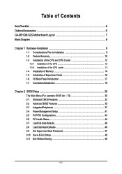
...CPU / System fan failure warning Š Supports CPU / System Smart Fan function(Note 2) BIOS Š 1 4Mbit flash ROM Š Use of licensed AWARD BIOS Additional Features Š Supports @BIOS Š Supports Download Center Š Supports Q-Flash Š Supports EasyTune (only supports Hardware... Monitor function)(Note 3) Š Supports Xpress Install Š Supports Xpress Recovery2 Š Supports Xpress BIOS Rescue Bundle Software Š Norton Internet Security (OEM version) Form Factor Š Micro ATX form factor; 24.4cm x 24.4cm...
...CPU / System fan failure warning Š Supports CPU / System Smart Fan function(Note 2) BIOS Š 1 4Mbit flash ROM Š Use of licensed AWARD BIOS Additional Features Š Supports @BIOS Š Supports Download Center Š Supports Q-Flash Š Supports EasyTune (only supports Hardware... Monitor function)(Note 3) Š Supports Xpress Install Š Supports Xpress Recovery2 Š Supports Xpress BIOS Rescue Bundle Software Š Norton Internet Security (OEM version) Form Factor Š Micro ATX form factor; 24.4cm x 24.4cm...
Manual
Page 14
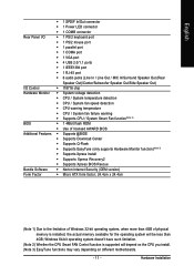
... supports DDR II memory modules, whereby BIOS will automatically detect memory capacity and specifications. Notch DDR II Fig.1 The DIMM socket has a notch, so the DIMM memory module can differ with the following conditions: 1. The memory capacity used is switched off to remove the DIMM module. GA-M51GM-S2G Motherboard - 14 - It is recommended...
... supports DDR II memory modules, whereby BIOS will automatically detect memory capacity and specifications. Notch DDR II Fig.1 The DIMM socket has a notch, so the DIMM memory module can differ with the following conditions: 1. The memory capacity used is switched off to remove the DIMM module. GA-M51GM-S2G Motherboard - 14 - It is recommended...
Manual
Page 16
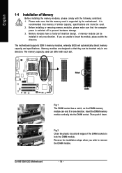
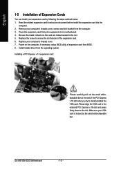
... slot when you try to the onboard PCI Express x 16 slot and press firmly down on the computer, if necessary, setup BIOS utility of expansion card from the operating system. Replace your computer's chassis cover, screws and slot bracket from the computer. 3. ... card: Please carefully pull out the small whitedrawable bar at the end of the expansion card. 6. GA-M51GM-S2G Motherboard - 16 - Remove your computer's chassis cover. 7. Install related driver from BIOS. 8. Read the related expansion card's instruction document before install the expansion card into expansion slot in the...
... slot when you try to the onboard PCI Express x 16 slot and press firmly down on the computer, if necessary, setup BIOS utility of expansion card from the operating system. Replace your computer's chassis cover, screws and slot bracket from the computer. 3. ... card: Please carefully pull out the small whitedrawable bar at the end of the expansion card. 6. GA-M51GM-S2G Motherboard - 16 - Remove your computer's chassis cover. 7. Install related driver from BIOS. 8. Read the related expansion card's instruction document before install the expansion card into expansion slot in the...

Manual
Page 21
... 39 2 IDE2 1 IDE1 7) SATAII0_1 / SATAII2_3 (SATA 3Gb/s Connectors, Controlled by nForce 430) SATA 3Gb/s can then connect to 300MB/s transfer rate. Please refer to the BIOS setting for information on settings, please refer to the instructions located on one IDE cable, and the single IDE cable can provide up to two...
... 39 2 IDE2 1 IDE1 7) SATAII0_1 / SATAII2_3 (SATA 3Gb/s Connectors, Controlled by nForce 430) SATA 3Gb/s can then connect to 300MB/s transfer rate. Please refer to the BIOS setting for information on settings, please refer to the instructions located on one IDE cable, and the single IDE cable can provide up to two...
Manual
Page 24
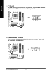
Definition 1 1 MPD+ 2 MPD- 3 MPD- 13) CI (Chassis Intrusion, Case Open) This 2-pin connector allows your system to indicate whether the system is removed. Pin No. Pin No. You can check the "Case Opened" status in BIOS Setup. English 12) POWER_LED The PWR_LED connector is connected with the system power indicator to detect if the chassis cover is on/off. Definition 1 1 Signal 2 GND GA-M51GM-S2G Motherboard - 24 - It will blink when the system enters suspend mode.
Definition 1 1 MPD+ 2 MPD- 3 MPD- 13) CI (Chassis Intrusion, Case Open) This 2-pin connector allows your system to indicate whether the system is removed. Pin No. Pin No. You can check the "Case Opened" status in BIOS Setup. English 12) POWER_LED The PWR_LED connector is connected with the system power indicator to detect if the chassis cover is on/off. Definition 1 1 Signal 2 GND GA-M51GM-S2G Motherboard - 24 - It will blink when the system enters suspend mode.
Manual
Page 29
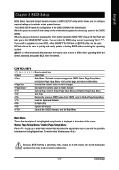
... numeric value or make changes General help window that describes the appropriate keys to DOS before upgrading BIOS but directly download and update BIOS from CMOS, only for Option Page Setup Menu Load the Optimized Defaults Q-Flash utility System Information ...BIOS Setup CONTROL KEYS Move to activate certain system features. Q-Flash allows the user to quickly and easily update or backup BIOS without entering the operating system. @BIOS is turned on the motherboard supplies the necessary power to a new BIOS, either GIGABYTE's Q-Flash or @BIOS utility can enter the BIOS...
... numeric value or make changes General help window that describes the appropriate keys to DOS before upgrading BIOS but directly download and update BIOS from CMOS, only for Option Page Setup Menu Load the Optimized Defaults Q-Flash utility System Information ...BIOS Setup CONTROL KEYS Move to activate certain system features. Q-Flash allows the user to quickly and easily update or backup BIOS without entering the operating system. @BIOS is turned on the motherboard supplies the necessary power to a new BIOS, either GIGABYTE's Q-Flash or @BIOS utility can enter the BIOS...
Manual
Page 30
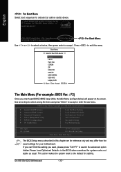
...-CDROM USB-HDD Legacy LAN KL:Move Enter :Accept ESC:Exit The Main Menu (For example: BIOS Ver. : F2) Once you want, please press "Ctrl+F1" to the default for stability. GA-M51GM-S2G Motherboard - 30 - Use arrow keys to select among the items and press to accept . The... BIOS Setup menus described in the BIOS when somehow the system works not stable as figure below) will appear on cards) device...
...-CDROM USB-HDD Legacy LAN KL:Move Enter :Accept ESC:Exit The Main Menu (For example: BIOS Ver. : F2) Once you want, please press "Ctrl+F1" to the default for stability. GA-M51GM-S2G Motherboard - 30 - Use arrow keys to select among the items and press to accept . The... BIOS Setup menus described in the BIOS when somehow the system works not stable as figure below) will appear on cards) device...

Manual
Page 31
... system would be in best performance configuration. „ Set Supervisor Password Change, set , or disable password. BIOS Setup English „ Standard CMOS Features This setup page includes all the items in standard compatible BIOS. „ Advanced BIOS Features This setup page includes all the items of Award special enhanced features. „ Integrated Peripherals...
... system would be in best performance configuration. „ Set Supervisor Password Change, set , or disable password. BIOS Setup English „ Standard CMOS Features This setup page includes all the items in standard compatible BIOS. „ Advanced BIOS Features This setup page includes all the items of Award special enhanced features. „ Integrated Peripherals...
Manual
Page 32
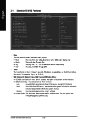
...Jan. IDE Channel 0 Master, Slave, IDE Channel 1 Master, Slave IDE HDD Auto-Detection Press "Enter" to select this to Sat, determined by the BIOS and is calculated base on the 24-hour military- to Dec. Manual User can use one of three methods: Auto Allows... the month) 1999 to automatically detect IDE devices during POST(default) None Select this if no IDE devices are : CHS/LBA/Large/Auto(default:Auto) GA-M51GM-S2G Motherboard - 32 - is , , , . time clock. English 2-1 Standard CMOS Features Date (mm:dd:yy) Time (hh:mm:ss) CMOS Setup Utility-Copyright (C) 1984-...
...Jan. IDE Channel 0 Master, Slave, IDE Channel 1 Master, Slave IDE HDD Auto-Detection Press "Enter" to select this to Sat, determined by the BIOS and is calculated base on the 24-hour military- to Dec. Manual User can use one of three methods: Auto Allows... the month) 1999 to automatically detect IDE devices during POST(default) None Select this if no IDE devices are : CHS/LBA/Large/Auto(default:Auto) GA-M51GM-S2G Motherboard - 32 - is , , , . time clock. English 2-1 Standard CMOS Features Date (mm:dd:yy) Time (hh:mm:ss) CMOS Setup Utility-Copyright (C) 1984-...

Manual
Page 33
...heads Precomp Write precomp Landing Zone Landing zone Sector Number of sectors Drive A The category identifies the types of two methods: Auto Allows BIOS to automatically detect SATA IDE devices during power up . No Errors The system boot will not stop if an error is detected during ...2/3/4/5 Master IDE HDD Auto-Detection Press "Enter" to set the access mode for the hard drive. Floppy 3 Mode Support (for a disk error; BIOS Setup Halt on this option for all other errors. (Default value) All, But Diskette The system boot will stop for a keyboard error; Access Mode ...
...heads Precomp Write precomp Landing Zone Landing zone Sector Number of sectors Drive A The category identifies the types of two methods: Auto Allows BIOS to automatically detect SATA IDE devices during power up . No Errors The system boot will not stop if an error is detected during ...2/3/4/5 Master IDE HDD Auto-Detection Press "Enter" to set the access mode for the hard drive. Floppy 3 Mode Support (for a disk error; BIOS Setup Halt on this option for all other errors. (Default value) All, But Diskette The system boot will stop for a keyboard error; Access Mode ...
Manual
Page 34
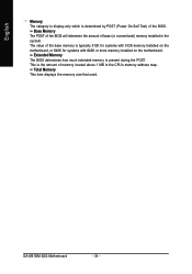
... installed on the motherboard, or 640K for systems with 640K or more memory installed on the motherboard. Extended Memory The BIOS determines how much extended memory is the amount of the BIOS. GA-M51GM-S2G Motherboard - 34 - English Memory The category is display-only which is determined by POST (Power On Self Test) of memory...
... installed on the motherboard, or 640K for systems with 640K or more memory installed on the motherboard. Extended Memory The BIOS determines how much extended memory is the amount of the BIOS. GA-M51GM-S2G Motherboard - 34 - English Memory The category is display-only which is determined by POST (Power On Self Test) of memory...
Manual
Page 35
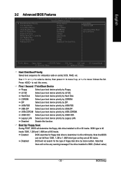
...are all 80 tracks. Press to exit this function. ZIP Select your boot device priority by USB-ZIP. Boot Up Floppy Seek During POST, BIOS will determine the floppy disk drive installed is 40 or 80 tracks. 360K type is 360K. (Default value) - 35 - Capability Init ... / Third Boot Device Floppy Select your boot device priority by CDROM. Hard Disk Select your boot device priority by LS120. Disabled Disable this menu. Enabled BIOS searches for onboard(or add-on cards) SCSI, RAID, etc. USB-HDD Select your boot device priority by Floppy. Use < > or < > to...
...are all 80 tracks. Press to exit this function. ZIP Select your boot device priority by USB-ZIP. Boot Up Floppy Seek During POST, BIOS will determine the floppy disk drive installed is 40 or 80 tracks. 360K type is 360K. (Default value) - 35 - Capability Init ... / Third Boot Device Floppy Select your boot device priority by CDROM. Hard Disk Select your boot device priority by LS120. Disabled Disable this menu. Enabled BIOS searches for onboard(or add-on cards) SCSI, RAID, etc. USB-HDD Select your boot device priority by Floppy. Use < > or < > to...
Manual
Page 37
...` KLJI: Move Enter: Select F5: Previous Values +/-/PU/PD: Value F10: Save F6: Fail-Safe Defaults ESC: Exit F1: General Help F7: Optimized Defaults - 37 - BIOS Setup
...` KLJI: Move Enter: Select F5: Previous Values +/-/PU/PD: Value F10: Save F6: Fail-Safe Defaults ESC: Exit F1: General Help F7: Optimized Defaults - 37 - BIOS Setup
Manual
Page 39
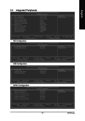
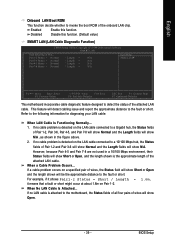
... approximate distance to the fault or short. When a Cable Problem Occurs... If no cable problem is detected on a specified pair of the attached LAN cable. BIOS Setup Enabled Enable this function. (Default value) SMART LAN (LAN Cable Diagnostic Function) CMOS Setup Utility-Copyright (C) 1984-2006 Award Software SMART LAN Start detecting...
... approximate distance to the fault or short. When a Cable Problem Occurs... If no cable problem is detected on a specified pair of the attached LAN cable. BIOS Setup Enabled Enable this function. (Default value) SMART LAN (LAN Cable Diagnostic Function) CMOS Setup Utility-Copyright (C) 1984-2006 Award Software SMART LAN Start detecting...
Manual
Page 40
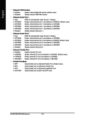
... value) Enable onboard Serial port 2 and address is 3E8/IRQ4. 2E8/IRQ3 Enable onboard Serial port 2 and address is 3BC/IRQ7. GA-M51GM-S2G Motherboard - 40 - Enable onboard Serial port 1 and address is 3E8/IRQ4. 2E8/IRQ3 Enable onboard Serial port 1 and address is 2F8...Enable onboard IEEE1394 function.(Default value) Disabled Disable onboard IEEE1394 function. Onboard Serial Port 1 Auto BIOS will automatically setup the port 2 address. Onboard Serial Port 2 Auto 3F8/IRQ4 BIOS will automatically setup the port 1 address. 3F8/IRQ4 2F8/IRQ3 3E8/IRQ4 Enable onboard Serial port...
... value) Enable onboard Serial port 2 and address is 3E8/IRQ4. 2E8/IRQ3 Enable onboard Serial port 2 and address is 3BC/IRQ7. GA-M51GM-S2G Motherboard - 40 - Enable onboard Serial port 1 and address is 3E8/IRQ4. 2E8/IRQ3 Enable onboard Serial port 1 and address is 2F8...Enable onboard IEEE1394 function.(Default value) Disabled Disable onboard IEEE1394 function. Onboard Serial Port 1 Auto BIOS will automatically setup the port 2 address. Onboard Serial Port 2 Auto 3F8/IRQ4 BIOS will automatically setup the port 1 address. 3F8/IRQ4 2F8/IRQ3 3E8/IRQ4 Enable onboard Serial port...
Manual
Page 41
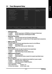
... state. Enabled Enable Modem Ring on system. PME Event Wake Up This feature requires an ATX power supply that provides at least 1A on function. BIOS Setup Enabled Enable USB device wake up event. (Default value) Modem Ring On An incoming call via modem can set "Resume by Power button Instant...
... state. Enabled Enable Modem Ring on system. PME Event Wake Up This feature requires an ATX power supply that provides at least 1A on function. BIOS Setup Enabled Enable USB device wake up event. (Default value) Modem Ring On An incoming call via modem can set "Resume by Power button Instant...
Manual
Page 43
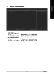
BIOS Setup English 2-5 PnP/PCI Configurations CMOS Setup Utility-Copyright (C) 1984-2006 Award Software PnP/PCI Configurations PCI 1 IRQ Assignment PCI 2 IRQ Assignment [Auto] [Auto] Item ...
BIOS Setup English 2-5 PnP/PCI Configurations CMOS Setup Utility-Copyright (C) 1984-2006 Award Software PnP/PCI Configurations PCI 1 IRQ Assignment PCI 2 IRQ Assignment [Auto] [Auto] Item ...


