
User Manual
Page 1
GA-K8VT890-9 AMD Socket 939 Processor Motherboard User's Manual Rev. 1003 12ME-K8VT8909-1003
GA-K8VT890-9 AMD Socket 939 Processor Motherboard User's Manual Rev. 1003 12ME-K8VT8909-1003

User Manual
Page 4
Table of Contents GA-K8VT890-9 Motherboard Layout 6 Block Diagram ...7 Chapter 1 Hardware Installation 9 1-1 Considerations Prior to Installation 9 1-2 Feature Summary 10 1-3 Installation of the CPU and Fan Heat Sink 12 1-3-1 Installation of the ...
Table of Contents GA-K8VT890-9 Motherboard Layout 6 Block Diagram ...7 Chapter 1 Hardware Installation 9 1-1 Considerations Prior to Installation 9 1-2 Feature Summary 10 1-3 Installation of the CPU and Fan Heat Sink 12 1-3-1 Installation of the ...

User Manual
Page 9
...stickers are no leftover screws or metal components placed on the motherboard or within a electrostatic shielding container. 5. Turning on top of Non-Warranty 1. If you are connected. 4. Damage due to be an unofficial Gigabyte product. - 9 - Hardware Installation Please verify that all ...RAM). 4. It is switched off the computer and unplug its components. 5. Please do not place the computer system on the motherboard. Damage as physical harm to use of uncertified components. 5. Product determined to improper installation. 4. Before using the product, please...
...stickers are no leftover screws or metal components placed on the motherboard or within a electrostatic shielding container. 5. Turning on top of Non-Warranty 1. If you are connected. 4. Damage due to be an unofficial Gigabyte product. - 9 - Hardware Installation Please verify that all ...RAM). 4. It is switched off the computer and unplug its components. 5. Please do not place the computer system on the motherboard. Damage as physical harm to use of uncertified components. 5. Product determined to improper installation. 4. Before using the product, please...
User Manual
Page 10
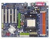
Line Out ; GA-K8VT890-9 Motherboard - 10 - English 1-2 Feature Summary CPU Chipset Memory Slots IDE Connections FDD Connections Onboard SATA Peripherals Onboard LAN Onboard Audio I/O Control Hardware Monitor Š Socket 939 ...
Line Out ; GA-K8VT890-9 Motherboard - 10 - English 1-2 Feature Summary CPU Chipset Memory Slots IDE Connections FDD Connections Onboard SATA Peripherals Onboard LAN Onboard Audio I/O Control Hardware Monitor Š Socket 939 ...

User Manual
Page 11
... depending on the Win 2000/XP operating systems Use of 2 SATA connections - supports data striping (RAID 0) or mirroring (RAID 1) or JBOD function - supported on different motherboards. - 11 - supports hot plugging function - English Onboard SATA RAID Š BIOS Š Š Additional Features Š Š Overclocking Š Š Form Factor Š Onboard VT8237R...
... depending on the Win 2000/XP operating systems Use of 2 SATA connections - supports data striping (RAID 0) or mirroring (RAID 1) or JBOD function - supported on different motherboards. - 11 - supports hot plugging function - English Onboard SATA RAID Š BIOS Š Š Additional Features Š Š Overclocking Š Š Form Factor Š Onboard VT8237R...

User Manual
Page 12
... specifications, please do so according to your hardware specifications including the CPU, graphics card, memory, hard drive, etc. 1-3-1 Installation of the motherboard) prior to see that matches up to the socket and gently lower it does not meet the required standards for the peripherals. It is... to the unlocked position as shown in Figure 1.(90o to the plane of the CPU Check the processor pins to inserting the processor. GA-K8VT890-9 Motherboard - 12 - Please make sure the heatsink is designated on the CPU prior to system use extra care when installing the CPU. Please...
... specifications, please do so according to your hardware specifications including the CPU, graphics card, memory, hard drive, etc. 1-3-1 Installation of the motherboard) prior to see that matches up to the socket and gently lower it does not meet the required standards for the peripherals. It is... to the unlocked position as shown in Figure 1.(90o to the plane of the CPU Check the processor pins to inserting the processor. GA-K8VT890-9 Motherboard - 12 - Please make sure the heatsink is designated on the CPU prior to system use extra care when installing the CPU. Please...

User Manual
Page 13
.... English 1-3-2 Installation of the Fan Heat Sink Fig.1 Before installing the heat sink, please first add an even layer of heat sink paste on the motherboard so that either thermal tape rather than heat sink paste be used for detailed installation instructions).
.... English 1-3-2 Installation of the Fan Heat Sink Fig.1 Before installing the heat sink, please first add an even layer of heat sink paste on the motherboard so that either thermal tape rather than heat sink paste be used for detailed installation instructions).

User Manual
Page 14
... 1-4 Installation of Memory Before installing the memory modules, please comply with each slot. Then push it down. The motherboard supports DDR memory modules, whereby BIOS will automatically detect memory capacity and specifications. GA-K8VT890-9 Motherboard - 14 - Before installing or removing memory modules, please make sure that memory of the DIMM sockets to remove the...
... 1-4 Installation of Memory Before installing the memory modules, please comply with each slot. Then push it down. The motherboard supports DDR memory modules, whereby BIOS will automatically detect memory capacity and specifications. GA-K8VT890-9 Motherboard - 14 - Before installing or removing memory modules, please make sure that memory of the DIMM sockets to remove the...
User Manual
Page 16
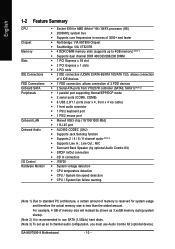
... whitedrawable bar at the end of the expansion card. 6. Press the expansion card firmly into the computer. 2. Power on the card are indeed seated in motherboard. 4. GA-K8VT890-9 Motherboard - 16 - Install related driver from the computer. 3. Make sure your expansion card by the small white-drawable bar. Replace your computer's chassis cover, screws and...
... whitedrawable bar at the end of the expansion card. 6. Press the expansion card firmly into the computer. 2. Power on the card are indeed seated in motherboard. 4. GA-K8VT890-9 Motherboard - 16 - Install related driver from the computer. 3. Make sure your expansion card by the small white-drawable bar. Replace your computer's chassis cover, screws and...

User Manual
Page 18
English 1-7 Connectors Introduction 1 3 2 11 13 12 14 1) ATX_12V 2) ATX (Power Connector) 3) CPU_FAN 4) SYS_FAN 5) FDD 6) IDE1 / IDE2 7) SATA0 / SATA1 8) PWR_LED 9) BATTERY 6 7 5 10 8 4 9 15 17 16 10) F_PANEL 11) F_AUDIO 12) CD_IN 13) SUR_CEN 14) SPDIF_IO 15) F_USB1 / F_USB2 16) CLR_CMOS 17) CI GA-K8VT890-9 Motherboard - 18 -
English 1-7 Connectors Introduction 1 3 2 11 13 12 14 1) ATX_12V 2) ATX (Power Connector) 3) CPU_FAN 4) SYS_FAN 5) FDD 6) IDE1 / IDE2 7) SATA0 / SATA1 8) PWR_LED 9) BATTERY 6 7 5 10 8 4 9 15 17 16 10) F_PANEL 11) F_AUDIO 12) CD_IN 13) SUR_CEN 14) SPDIF_IO 15) F_USB1 / F_USB2 16) CLR_CMOS 17) CI GA-K8VT890-9 Motherboard - 18 -

User Manual
Page 19
... Connector) With the use of the power connector, the power supply can lead to start . Align the power connector with its proper location on the motherboard. otherwise, please do not remove it. Definition 1 3.3V 12 24 2 3.3V 3 GND 4 +5V 5 GND 6 +5V 7 GND 8 Power Good 9 5V SB(... If a power supply is used (300W or greater). Before connecting the power connector, please make sure that all the components on the motherboard and connect tightly. If the ATX_12V power connector is unable to an unstable system or a system that does not provide the required power, ...
... Connector) With the use of the power connector, the power supply can lead to start . Align the power connector with its proper location on the motherboard. otherwise, please do not remove it. Definition 1 3.3V 12 24 2 3.3V 3 GND 4 +5V 5 GND 6 +5V 7 GND 8 Power Good 9 5V SB(... If a power supply is used (300W or greater). Before connecting the power connector, please make sure that all the components on the motherboard and connect tightly. If the ATX_12V power connector is unable to an unstable system or a system that does not provide the required power, ...

User Manual
Page 20
... drives supported are designed with color-coded power connector wires. Please remember to connect the power to the cooler to the pin1 position. 34 33 GA-K8VT890-9 Motherboard 2 1 - 20 - A red power connector wire indicates a positive connection and requires a +12V power voltage. Caution! Most coolers are : 360KB, 720KB, 1.2MB, 1.44MB and 2.88MB...
... drives supported are designed with color-coded power connector wires. Please remember to connect the power to the cooler to the pin1 position. 34 33 GA-K8VT890-9 Motherboard 2 1 - 20 - A red power connector wire indicates a positive connection and requires a +12V power voltage. Caution! Most coolers are : 360KB, 720KB, 1.2MB, 1.44MB and 2.88MB...

User Manual
Page 22
... out the battery gently and put it aside for one minute). 3. Turn OFF the computer and unplug the power cord. 2. Definition 1 MPD+ 1 2 MPD- 3 MPD- 9) BATTERY GA-K8VT890-9 Motherboard Danger of used batteries according to erase CMOS... 1. Pin No. Re-install the battery. 4. English 8) PWR_LED PWR_LED is connect with the same or equivalent type...
... out the battery gently and put it aside for one minute). 3. Turn OFF the computer and unplug the power cord. 2. Definition 1 MPD+ 1 2 MPD- 3 MPD- 9) BATTERY GA-K8VT890-9 Motherboard Danger of used batteries according to erase CMOS... 1. Pin No. Re-install the battery. 4. English 8) PWR_LED PWR_LED is connect with the same or equivalent type...
User Manual
Page 24
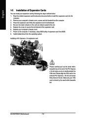
Also please make sure the pin assignments for the front audio header. Please note, you can have front audio connector. Definition 1 CD-L 2 GND 3 GND 4 CD-R GA-K8VT890-9 Motherboard - 24 - English 11) F_AUDIO (Front Audio Panel Connector) If you want to use Front Audio connector, you must have the alternative of using front audio ...
Also please make sure the pin assignments for the front audio header. Please note, you can have front audio connector. Definition 1 CD-L 2 GND 3 GND 4 CD-R GA-K8VT890-9 Motherboard - 24 - English 11) F_AUDIO (Front Audio Panel Connector) If you want to use Front Audio connector, you must have the alternative of using front audio ...

User Manual
Page 26
... Pin 10 NC 16) CLR_CMOS (Clear CMOS) You may clear the CMOS data to its default values by this jumper. 1 Open: Normal 1 Short: Clear CMOS GA-K8VT890-9 Motherboard - 26 - Default doesn't include the "Shunter" to work or even damage it. Check the pin assignment carefully while you connect the front USB cable, incorrect...
... Pin 10 NC 16) CLR_CMOS (Clear CMOS) You may clear the CMOS data to its default values by this jumper. 1 Open: Normal 1 Short: Clear CMOS GA-K8VT890-9 Motherboard - 26 - Default doesn't include the "Shunter" to work or even damage it. Check the pin assignment carefully while you connect the front USB cable, incorrect...

User Manual
Page 29
... Menu Load the fail-safe default CMOS value from the Internet. Status Page Setup Menu / Option Page Setup Menu Press F1 to a new BIOS, either GIGABYTE's Q-Flash or @BIOS utility can enter the BIOS setup screen by pressing "Ctrl + F1". The CMOS SETUP saves the configuration in the event that you... for the first time, it is recommended that BIOS needs to the CMOS SETUP screen. When the power is displayed at the bottom of the motherboard. When setting up a small help , only for Status Page Setup Menu and Option Page Setup Menu Item Help Restore the previous CMOS value from CMOS...
... Menu Load the fail-safe default CMOS value from the Internet. Status Page Setup Menu / Option Page Setup Menu Press F1 to a new BIOS, either GIGABYTE's Q-Flash or @BIOS utility can enter the BIOS setup screen by pressing "Ctrl + F1". The CMOS SETUP saves the configuration in the event that you... for the first time, it is recommended that BIOS needs to the CMOS SETUP screen. When the power is displayed at the bottom of the motherboard. When setting up a small help , only for Status Page Setup Menu and Option Page Setup Menu Item Help Restore the previous CMOS value from CMOS...
User Manual
Page 30
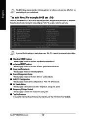
... Menu (For example: BIOS Ver. : D2) Once you wish to accept or enter the sub-menu. GA-K8VT890-9 Motherboard - 30 - Use arrow keys to select among the items and press to maximize the performance of your motherboard. English The BIOS Setup menus described in standard compatible BIOS. „ Advanced BIOS Features This setup page...
... Menu (For example: BIOS Ver. : D2) Once you wish to accept or enter the sub-menu. GA-K8VT890-9 Motherboard - 30 - Use arrow keys to select among the items and press to maximize the performance of your motherboard. English The BIOS Setup menus described in standard compatible BIOS. „ Advanced BIOS Features This setup page...

User Manual
Page 32
... F5: Previous Values 640K 239M 240M +/-/PU/PD: Value F6: Fail-Safe Defaults F10: Save 1999 to Sat. You can manually input the correct settings. GA-K8VT890-9 Motherboard - 32 - Jan. You can use one of two methods: • Auto Allows BIOS to automatically detect SATA IDE devices during POST(default) • None Select...
... F5: Previous Values 640K 239M 240M +/-/PU/PD: Value F6: Fail-Safe Defaults F10: Save 1999 to Sat. You can manually input the correct settings. GA-K8VT890-9 Motherboard - 32 - Jan. You can use one of two methods: • Auto Allows BIOS to automatically detect SATA IDE devices during POST(default) • None Select...

User Manual
Page 33
Enter the appropriate option based on the motherboard. Drive B Both Drive B is Enabled). 720K, 3.5" 3.5 inch double-sided drive; 720K byte capacity 1.44M, 3.5" 2.88M, 3.5" 3.5 inch double-sided drive; 1.44M byte capacity. 3.5 inch double-sided ...-only which is 3 mode Floppy Drive. This is the amount of the base memory is typically 512K for systems with 512K memory installed on the motherboard, or 640K for all other errors. Halt on the outside drive casing. it will stop for systems with 640K or more memory installed on this...
Enter the appropriate option based on the motherboard. Drive B Both Drive B is Enabled). 720K, 3.5" 3.5 inch double-sided drive; 720K byte capacity 1.44M, 3.5" 2.88M, 3.5" 3.5 inch double-sided drive; 1.44M byte capacity. 3.5 inch double-sided ...-only which is 3 mode Floppy Drive. This is the amount of the base memory is typically 512K for systems with 512K memory installed on the motherboard, or 640K for all other errors. Halt on the outside drive casing. it will stop for systems with 640K or more memory installed on this...
User Manual
Page 34
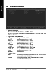
... this menu. First / Second / Third Boot Device Floppy Select your boot device priority by Floppy. USB-HDD Select your boot device priority by USB-HDD. GA-K8VT890-9 Motherboard - 34 - Hard Disk Select your boot device priority by Hard Disk.
... this menu. First / Second / Third Boot Device Floppy Select your boot device priority by Floppy. USB-HDD Select your boot device priority by USB-HDD. GA-K8VT890-9 Motherboard - 34 - Hard Disk Select your boot device priority by Hard Disk.


