User Manual
Page 5
Channel Audio Function Introduction 69 4-2 Troubleshooting 77 - 5 - Chapter 3 Drivers Installation 47 3-1 Install Chipset Drivers 47 3-2 SoftwareApplication 48 3-3 Software Information 48 3-4 Hardware Information 49 3-5 Contact Us ...49 Chapter 4 Appendix 51 4-1 Unique Software Utilities 51 4-1-1 Xpress Recovery Introduction 51 4-1-2 Flash BIOS Method Introduction 54 4-1-3 Serial ATA BIOS Setting Utility Introduction 63 4-1-4 2- / 4- / 6- / 8-
Channel Audio Function Introduction 69 4-2 Troubleshooting 77 - 5 - Chapter 3 Drivers Installation 47 3-1 Install Chipset Drivers 47 3-2 SoftwareApplication 48 3-3 Software Information 48 3-4 Hardware Information 49 3-5 Contact Us ...49 Chapter 4 Appendix 51 4-1 Unique Software Utilities 51 4-1-1 Xpress Recovery Introduction 51 4-1-2 Flash BIOS Method Introduction 54 4-1-3 Serial ATA BIOS Setting Utility Introduction 63 4-1-4 2- / 4- / 6- / 8-
User Manual
Page 15
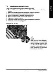
... the operating system. Remove your VGA card is locked by following the steps outlined below: 1. Press the expansion card firmly into the computer. 2. Install related driver from the computer. 3. Hardware Installation
... the operating system. Remove your VGA card is locked by following the steps outlined below: 1. Press the expansion card firmly into the computer. 2. Install related driver from the computer. 3. Hardware Installation
User Manual
Page 16
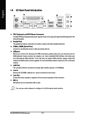
For more information please contact your OS does not support USB controller, please contact OS vendor for possible patch or driver upgrade. GA-K8VT800-RH Motherboard - 16 - have a standard USB interface. can use audio software to MIC In jack. COMA, COMB (Serial Port) Connects to this connector. LAN Port ...
For more information please contact your OS does not support USB controller, please contact OS vendor for possible patch or driver upgrade. GA-K8VT800-RH Motherboard - 16 - have a standard USB interface. can use audio software to MIC In jack. COMA, COMB (Serial Port) Connects to this connector. LAN Port ...
User Manual
Page 21
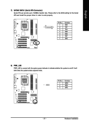
It will blink when the system enters suspend mode. Hardware Installation Pin No. Definition 1 GND 1 7 2 TXP 3 TXN 4 GND 5 RXN 6 RXP 7 GND 8) PWR_LED PWR_LED is connect with the system power indicator to work properly. Please refer to the BIOS setting for the Serial ATA and install the proper driver in order to indicate whether the system is on/off. Pin No. English 7) SATA0/ SATA1 (Serial ATA Connector) Serial ATA can provide up to 150MB/s transfer rate. Definition 1 MPD+ 1 2 MPD- 3 MPD- - 21 -
It will blink when the system enters suspend mode. Hardware Installation Pin No. Definition 1 GND 1 7 2 TXP 3 TXN 4 GND 5 RXN 6 RXP 7 GND 8) PWR_LED PWR_LED is connect with the system power indicator to work properly. Please refer to the BIOS setting for the Serial ATA and install the proper driver in order to indicate whether the system is on/off. Pin No. English 7) SATA0/ SATA1 (Serial ATA Connector) Serial ATA can provide up to 150MB/s transfer rate. Definition 1 MPD+ 1 2 MPD- 3 MPD- - 21 -
User Manual
Page 47
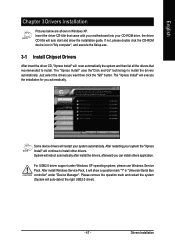
...then click the "GO" button. After install Windows Service Pack, it will scan automatically the system and then list all the drivers that came with your motherboard into your system automatically. in "Universal Serial Bus controller" under Windows XP operating system, please use ...Windows Service Pack. Just select the drivers you automatically. The "Xpress Install" uses the"Click and Go" technology to install other drivers. After restarting your system the "Xpress Install" will auto start and show a question mark ...
...then click the "GO" button. After install Windows Service Pack, it will scan automatically the system and then list all the drivers that came with your motherboard into your system automatically. in "Universal Serial Bus controller" under Windows XP operating system, please use ...Windows Service Pack. Just select the drivers you automatically. The "Xpress Install" uses the"Click and Go" technology to install other drivers. After restarting your system the "Xpress Install" will auto start and show a question mark ...
User Manual
Page 48
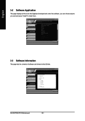
GA-K8VT800-RH Motherboard - 48 - English 3-2 Software Application This page displays all the tools that Gigabyte developed and some free software, you can choose anyone you want and press "install" to install them. 3-3 Software Information This page lists the contents of software and drivers in this CD-title.
GA-K8VT800-RH Motherboard - 48 - English 3-2 Software Application This page displays all the tools that Gigabyte developed and some free software, you can choose anyone you want and press "install" to install them. 3-3 Software Information This page lists the contents of software and drivers in this CD-title.
User Manual
Page 49
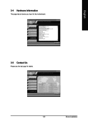
English 3-4 Hardware Information This page lists all device you have for this motherboard. 3-5 Contact Us Please see the last page for details. - 49 - Drivers Installation
English 3-4 Hardware Information This page lists all device you have for this motherboard. 3-5 Contact Us Please see the last page for details. - 49 - Drivers Installation
User Manual
Page 51
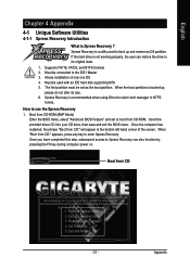
...When the boot partition is Xpress Recovery ? Execute Backup Utility 2. Remove Backup Image 4. Appendix Set Password 5. Exit and Restart Build 2011 - 51 - GIGABYTE Technology CO. , Ltd. 1. If the hard drive is not working properly, the user can also function by pressing the F9 key during computer power... Feature" and set as the boot partition. How to back up , please do not alter its original state. 1. Insert the provided driver CD into your CD drive, then save and exit the BIOS menu. Once you have completed this step, subsequent access to Xpress Recovery ...
...When the boot partition is Xpress Recovery ? Execute Backup Utility 2. Remove Backup Image 4. Appendix Set Password 5. Exit and Restart Build 2011 - 51 - GIGABYTE Technology CO. , Ltd. 1. If the hard drive is not working properly, the user can also function by pressing the F9 key during computer power... Feature" and set as the boot partition. How to back up , please do not alter its original state. 1. Insert the provided driver CD into your CD drive, then save and exit the BIOS menu. Once you have completed this step, subsequent access to Xpress Recovery ...

User Manual
Page 52
... is recommended that Xpress Recovery be immediately installed after OS and all required driver and software installations are complete. Intel 865PE AGPSet BIOS for 8IPE1000MT F1 Check System Health OK . . . GIGABYTE Technology CO. , Ltd. 1. Exit and Restart 1. Execute Restore Utility 3. GA-K8VT800-RH Motherboard - 52 - Execute Backup Utility 2. System storage capacity as well as...
... is recommended that Xpress Recovery be immediately installed after OS and all required driver and software installations are complete. Intel 865PE AGPSet BIOS for 8IPE1000MT F1 Check System Health OK . . . GIGABYTE Technology CO. , Ltd. 1. Exit and Restart 1. Execute Restore Utility 3. GA-K8VT800-RH Motherboard - 52 - Execute Backup Utility 2. System storage capacity as well as...
User Manual
Page 64
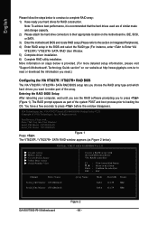
...the hard drive connectors to Enter VIA VT8237R / VT8237R+ SATA RAID User Window. 5) Complete driver installation. 6) Complete RAID utility installation. Scan Devices, Please wait... English Please follow the steps ...selection Exit Array Name Mode SATA SATA Size(GB) Status 111.79 Hdd 111.79 Hdd GA-K8VT800-RH Motherboard Figure 2 - 64 - VIA Technologies, Inc. More information on steps below...RAID type (For instance, enter to their appropriate location on our website at http:\\www.gigabyte.com.tw to read or download the information you need.) Configuring the VIA VT8237R / ...
...the hard drive connectors to Enter VIA VT8237R / VT8237R+ SATA RAID User Window. 5) Complete driver installation. 6) Complete RAID utility installation. Scan Devices, Please wait... English Please follow the steps ...selection Exit Array Name Mode SATA SATA Size(GB) Status 111.79 Hdd 111.79 Hdd GA-K8VT800-RH Motherboard Figure 2 - 64 - VIA Technologies, Inc. More information on steps below...RAID type (For instance, enter to their appropriate location on our website at http:\\www.gigabyte.com.tw to read or download the information you need.) Configuring the VIA VT8237R / ...

User Manual
Page 66
...the RAID configuration screen, you have to set block size, ranging from the RAID BIOS, the next step is to configure and load drivers under Windows. When the Auto create array will destroy all data on -screen instructions to complete manual setup of the hard disks marked with... Auto Setup: Select Auto Setup For Performance and press . VIA Tech. VIA Tech. message (Figure 5) appears, press to confirm or to Page 68. GA-K8VT800-RH Motherboard - 66 - VT8237 SATA RAID BIOS Ver 2.31 Auto Setup For Performance Array Mode RAID 0 (Striping) Select Disk Drives Block Size 64K Start ...
...the RAID configuration screen, you have to set block size, ranging from the RAID BIOS, the next step is to configure and load drivers under Windows. When the Auto create array will destroy all data on -screen instructions to complete manual setup of the hard disks marked with... Auto Setup: Select Auto Setup For Performance and press . VIA Tech. VIA Tech. message (Figure 5) appears, press to confirm or to Page 68. GA-K8VT800-RH Motherboard - 66 - VT8237 SATA RAID BIOS Ver 2.31 Auto Setup For Performance Array Mode RAID 0 (Striping) Select Disk Drives Block Size 64K Start ...
User Manual
Page 68
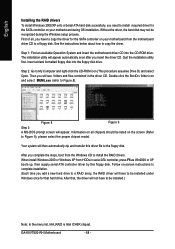
...The installation utility will appear. Quit the installation utility first. When install Windows 2000 or Windows XP from the Windows CD to install the RAID drivers. GA-K8VT800-RH Motherboard - 68 - Then you will not have to be listed on the screen (Refer to Figure 9), please select the proper chipset model.... After you complete the steps, boot from HDDs in the driver CD. After that hard drive. Follow on-screen instructions to complete installation. (Each time you add a new hard drive to a RAID array, ...
...The installation utility will appear. Quit the installation utility first. When install Windows 2000 or Windows XP from the Windows CD to install the RAID drivers. GA-K8VT800-RH Motherboard - 68 - Then you will not have to be listed on the screen (Refer to Figure 9), please select the proper chipset model.... After you complete the steps, boot from HDDs in the driver CD. After that hard drive. Follow on-screen instructions to complete installation. (Each time you add a new hard drive to a RAID array, ...
User Manual
Page 69
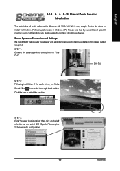
Please note that you use Audio Combo Kit (optional device). Appendix Channel Audio Function Introduction The installation of the audio driver, you find a Sound Effect icon on the left selection bar and select "2CH Speaker" to set up an 8 channel audio configuration, you want to complete 2 ...
Please note that you use Audio Combo Kit (optional device). Appendix Channel Audio Function Introduction The installation of the audio driver, you find a Sound Effect icon on the left selection bar and select "2CH Speaker" to set up an 8 channel audio configuration, you want to complete 2 ...

User Manual
Page 70
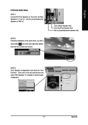
Line In (Rear Speaker Out) Line Out (Front Speaker Out) STEP 3: Click "Speaker Configuration" and select the "UAJ Function". Then click on the lower right hand taskbar. GA-K8VT800-RH Motherboard - 70 - STEP 2: Following installation of the audio driver, you find a Sound Effect icon on the left selection bar and select "4CH Speaker" to complete 4 channel audio configuration. Click the icon to "Line In". English 4 Channel Audio Setup STEP 1: Connect the Front Speakers to "Line Out", the Rear Speakers to select the function.
Line In (Rear Speaker Out) Line Out (Front Speaker Out) STEP 3: Click "Speaker Configuration" and select the "UAJ Function". Then click on the lower right hand taskbar. GA-K8VT800-RH Motherboard - 70 - STEP 2: Following installation of the audio driver, you find a Sound Effect icon on the left selection bar and select "4CH Speaker" to complete 4 channel audio configuration. Click the icon to "Line In". English 4 Channel Audio Setup STEP 1: Connect the Front Speakers to "Line Out", the Rear Speakers to select the function.
User Manual
Page 71
... "Line Out", the Rear Speakers to "Line In", and the Center/Subwoofer Speakers to complete 6 channel audio configuration. - 71 - STEP 2: Following installation of the audio driver, you find a Sound Effect icon on the left selection bar and select "6CH Speaker" to "MIC In". Then click on the lower right hand taskbar...
... "Line Out", the Rear Speakers to "Line In", and the Center/Subwoofer Speakers to complete 6 channel audio configuration. - 71 - STEP 2: Following installation of the audio driver, you find a Sound Effect icon on the left selection bar and select "6CH Speaker" to "MIC In". Then click on the lower right hand taskbar...

User Manual
Page 73
... the audio panel and the rear channels to the Surround-Kit "SUR BACK" port. (This method requires UAJ function) STEP 4: Following installation of the audio driver, you find a Sound Effect icon on the lower right hand taskbar.
... the audio panel and the rear channels to the Surround-Kit "SUR BACK" port. (This method requires UAJ function) STEP 4: Following installation of the audio driver, you find a Sound Effect icon on the lower right hand taskbar.


