User Manual
Page 1
GA-K8NSC-939 AMD Socket 939 Processor Motherboard User's Manual Rev. 1003 12ME-K8NSC939-1003
GA-K8NSC-939 AMD Socket 939 Processor Motherboard User's Manual Rev. 1003 12ME-K8NSC939-1003
User Manual
Page 2
Motherboard GA-K8NSC-939 Feb. 23, 2005 Motherboard GA-K8NSC-939 Feb. 23, 2005
Motherboard GA-K8NSC-939 Feb. 23, 2005 Motherboard GA-K8NSC-939 Feb. 23, 2005
User Manual
Page 4
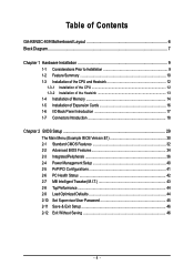
Table of Contents GA-K8NSC-939 Motherboard Layout 6 Block Diagram ...7 Chapter 1 Hardware Installation 9 1-1 Considerations Prior to Installation 9 1-2 Feature Summary 10 1-3 Installation of the CPU and Heatsink 12 1-3-1 Installation of the CPU 12 1-3-2 ...
Table of Contents GA-K8NSC-939 Motherboard Layout 6 Block Diagram ...7 Chapter 1 Hardware Installation 9 1-1 Considerations Prior to Installation 9 1-2 Feature Summary 10 1-3 Installation of the CPU and Heatsink 12 1-3-1 Installation of the CPU 12 1-3-2 ...
User Manual
Page 9
... that all cables and power connectors are required for warranty validation. 2. Prior to the use of electrostatic discharge (ESD). Turning on the motherboard. Damage as a result of the product, please consult a certified computer technician. Damage due to natural disaster, accident or human cause. ...can become damaged as a result of an antistatic pad or within the computer casing. 6. Please do not allow screws to be an unofficial Gigabyte product. - 9 - Thus, prior to wear an electrostatic discharge (ESD) cuff when handling electronic components (CPU, RAM). 4. It ...
... that all cables and power connectors are required for warranty validation. 2. Prior to the use of electrostatic discharge (ESD). Turning on the motherboard. Damage as a result of the product, please consult a certified computer technician. Damage due to natural disaster, accident or human cause. ...can become damaged as a result of an antistatic pad or within the computer casing. 6. Please do not allow screws to be an unofficial Gigabyte product. - 9 - Thus, prior to wear an electrostatic discharge (ESD) cuff when handling electronic components (CPU, RAM). 4. It ...

User Manual
Page 10
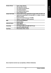
...138; ALC850 CODEC (UAJ) Š Supports Jack Sensing function Š Supports 2 / 4 / 6 / 8 channel audio (Note 2) Š Supports Line In ; GA-K8NSC-939 Motherboard - 10 - For example, 4GB of memory size will instead be shown as 3.xxGB memory during system startup. (Note 2) To set up to standard PC architecture... 1-2 Feature Summary CPU Chipset Memory Slots IDE Connections FDD Connections Onboard SATA Peripherals Onboard LAN Onboard Audio I/O Control Š Socket 939 for system usage and therefore the actual memory size is reserved for AMD AthlonTM 64 / 64 FX processor (K8) Š ...
...138; ALC850 CODEC (UAJ) Š Supports Jack Sensing function Š Supports 2 / 4 / 6 / 8 channel audio (Note 2) Š Supports Line In ; GA-K8NSC-939 Motherboard - 10 - For example, 4GB of memory size will instead be shown as 3.xxGB memory during system startup. (Note 2) To set up to standard PC architecture... 1-2 Feature Summary CPU Chipset Memory Slots IDE Connections FDD Connections Onboard SATA Peripherals Onboard LAN Onboard Audio I/O Control Š Socket 939 for system usage and therefore the actual memory size is reserved for AMD AthlonTM 64 / 64 FX processor (K8) Š ...
User Manual
Page 11
.../ DDR/ AGP/ HT-Link) Over Clock via BIOS (CPU/ AGP) ATX form factor; 30.5cm x 24.4cm (Note 3) EasyTune functions may vary depending on different motherboards. - 11 -
.../ DDR/ AGP/ HT-Link) Over Clock via BIOS (CPU/ AGP) ATX form factor; 30.5cm x 24.4cm (Note 3) EasyTune functions may vary depending on different motherboards. - 11 -
User Manual
Page 12
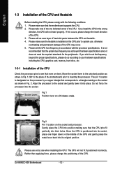
...the CPU, please comply with the processor specifications. It is positioned into place. Once the CPU is not recommended that the motherboard supports the CPU. 2. The CPU will not insert properly. Please set the CPU host frequency in the wrong direction, ... Installation of the CPU Check the processor pins to the plane of the CPU may occur. 5. GA-K8NSC-939 Motherboard - 12 - Please use , otherwise overheating and permanent damage of the motherboard) prior to system use extra care when installing the CPU. Please make sure the heatsink is designated ...
...the CPU, please comply with the processor specifications. It is positioned into place. Once the CPU is not recommended that the motherboard supports the CPU. 2. The CPU will not insert properly. Please set the CPU host frequency in the wrong direction, ... Installation of the CPU Check the processor pins to the plane of the CPU may occur. 5. GA-K8NSC-939 Motherboard - 12 - Please use , otherwise overheating and permanent damage of the motherboard) prior to system use extra care when installing the CPU. Please make sure the heatsink is designated ...

User Manual
Page 13
... sink. - 13 - English 1-3-2 Installation of the Heatsink Fig.1 Before installing the heat sink, please first add an even layer of heat sink paste on the motherboard so that either thermal tape rather than heat sink paste be used for detailed installation instructions). The heat sink may adhere to prevent CPU overheating...
... sink. - 13 - English 1-3-2 Installation of the Heatsink Fig.1 Before installing the heat sink, please first add an even layer of heat sink paste on the motherboard so that either thermal tape rather than heat sink paste be used for detailed installation instructions). The heat sink may adhere to prevent CPU overheating...
User Manual
Page 14
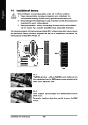
Memory modules have a foolproof insertion design. A memory module can only fit in one direction. The motherboard supports DDR memory modules, whereby BIOS will automatically detect memory capacity and specifications. Please make sure that they can differ ...DIMM module. The memory capacity used . 2. Reverse the installation steps when you are designed so that the computer power is supported by the motherboard. GA-K8NSC-939 Motherboard - 14 - If you wish to insert the module, please switch the direction. Before installing or removing memory modules, please make sure ...
Memory modules have a foolproof insertion design. A memory module can only fit in one direction. The motherboard supports DDR memory modules, whereby BIOS will automatically detect memory capacity and specifications. Please make sure that they can differ ...DIMM module. The memory capacity used . 2. Reverse the installation steps when you are designed so that the computer power is supported by the motherboard. GA-K8NSC-939 Motherboard - 14 - If you wish to insert the module, please switch the direction. Before installing or removing memory modules, please make sure ...
User Manual
Page 16
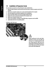
... slot bracket of the AGP slot when you try to the onboard AGP slot and press firmly down on the card are indeed seated in motherboard. 4. GA-K8NSC-939 Motherboard - 16 - Power on the computer, if necessary, setup BIOS utility of expansion card from the operating system.
... slot bracket of the AGP slot when you try to the onboard AGP slot and press firmly down on the card are indeed seated in motherboard. 4. GA-K8NSC-939 Motherboard - 16 - Power on the computer, if necessary, setup BIOS utility of expansion card from the operating system.

User Manual
Page 18
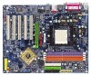
English 1-7 Connectors Introduction 13 8 7 11 12 13 16 14 1) ATX_12V 2) ATX (Power Connector) 3) CPU_FAN 4) SYS_FAN 5) NB_FAN 6) FDD 7) IDE1 / IDE2 8) SATA0_SB / SATA1_SB 9) PWR_LED 2 6 18 5 17 10 9 4 15 10) F_PANEL 11) F_AUDIO 12) CD_IN 13) SUR_CEN 14) SPDIF_IO 15) F_USB1 / F_USB2 16) IR_CIR 17) CLR_CMOS 18) BATTERY GA-K8NSC-939 Motherboard - 18 -
English 1-7 Connectors Introduction 13 8 7 11 12 13 16 14 1) ATX_12V 2) ATX (Power Connector) 3) CPU_FAN 4) SYS_FAN 5) NB_FAN 6) FDD 7) IDE1 / IDE2 8) SATA0_SB / SATA1_SB 9) PWR_LED 2 6 18 5 17 10 9 4 15 10) F_PANEL 11) F_AUDIO 12) CD_IN 13) SUR_CEN 14) SPDIF_IO 15) F_USB1 / F_USB2 16) IR_CIR 17) CLR_CMOS 18) BATTERY GA-K8NSC-939 Motherboard - 18 -

User Manual
Page 19
... 4 +5V 5 GND 6 +5V 7 GND 8 Power Good 9 5V SB (stand by +5V) 10 +12V 1 11 11 3.3V 12 -12V 13 GND 14 PS_ON(soft on the motherboard and connect tightly. Align the power connector with its proper location on /off) 15 GND 16 GND 17 GND 18 -5V 19 +5V 20 +5V... Pin No. 1 2 3 4 Definition GND GND +12V +12V Pin No. English 1/2) ATX_12V / ATX (Power Connector) With the use a power supply that all the components on the motherboard.
... 4 +5V 5 GND 6 +5V 7 GND 8 Power Good 9 5V SB (stand by +5V) 10 +12V 1 11 11 3.3V 12 -12V 13 GND 14 PS_ON(soft on the motherboard and connect tightly. Align the power connector with its proper location on /off) 15 GND 16 GND 17 GND 18 -5V 19 +5V 20 +5V... Pin No. 1 2 3 4 Definition GND GND +12V +12V Pin No. English 1/2) ATX_12V / ATX (Power Connector) With the use a power supply that all the components on the motherboard.
User Manual
Page 20
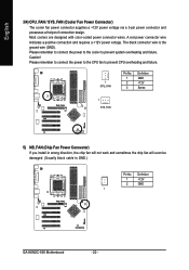
... chip fan will not work and sometimes the chip fan will even be damaged. (Usually black cable is the ground wire (GND). Definition 1 +12V 2 GND 1 GA-K8NSC-939 Motherboard - 20 - A red power connector wire indicates a positive connection and requires a +12V power voltage. Caution! The black connector wire is GND.) Pin No. Please remember to...
... chip fan will not work and sometimes the chip fan will even be damaged. (Usually black cable is the ground wire (GND). Definition 1 +12V 2 GND 1 GA-K8NSC-939 Motherboard - 20 - A red power connector wire indicates a positive connection and requires a +12V power voltage. Caution! The black connector wire is GND.) Pin No. Please remember to...
User Manual
Page 22
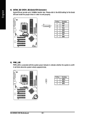
English 8) SATA0_SB / SATA1_SB (Serial ATA Connector) Serial ATA can provide up to work properly. Pin No. GA-K8NSC-939 Motherboard - 22 - Pin No. Please refer to the BIOS setting for the Serial ATA and install the proper driver in order to 150MB/s transfer rate. It will blink when the system enters suspend mode. Definition 1 GND 1 7 2 TXP 3 TXN 4 GND 5 RXN 6 RXP 7 GND 9) PWR_LED PWR_LED is connected with the system power indicator to indicate whether the system is on/off. Definition 1 MPD+ 2 MPD- 1 3 MPD-
English 8) SATA0_SB / SATA1_SB (Serial ATA Connector) Serial ATA can provide up to work properly. Pin No. GA-K8NSC-939 Motherboard - 22 - Pin No. Please refer to the BIOS setting for the Serial ATA and install the proper driver in order to 150MB/s transfer rate. It will blink when the system enters suspend mode. Definition 1 GND 1 7 2 TXP 3 TXN 4 GND 5 RXN 6 RXP 7 GND 9) PWR_LED PWR_LED is connected with the system power indicator to indicate whether the system is on/off. Definition 1 MPD+ 2 MPD- 1 3 MPD-
User Manual
Page 24
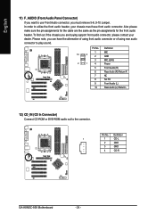
... connector or of using rear audio connector to play sound. In order to utilize the front audio header, your dealer. Definition 1 1 CD-L 2 GND 3 GND 4 CD-R GA-K8NSC-939 Motherboard - 24 - Pin No. English 11) F_AUDIO (Front Audio Panel Connector) If you want to use Front Audio connector, you can have front audio connector. Also...
... connector or of using rear audio connector to play sound. In order to utilize the front audio header, your dealer. Definition 1 1 CD-L 2 GND 3 GND 4 CD-R GA-K8NSC-939 Motherboard - 24 - Pin No. English 11) F_AUDIO (Front Audio Panel Connector) If you want to use Front Audio connector, you can have front audio connector. Also...
User Manual
Page 26
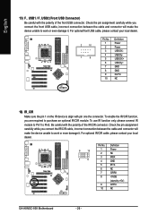
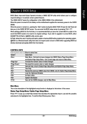
... USB cable, please contact your local dealer. 6 10 1 5 Pin No. 1 2 3 4 5 6 7 8 9 10 Definition Power NC IRRX GND IRTX NC CIRRX +5VSB (stand by +5V) CIRTX NC GA-K8NSC-939 Motherboard - 26 - Check the pin assignment carefully while you connect the front USB cable, incorrect connection between the cable and connector will make the device unable...
... USB cable, please contact your local dealer. 6 10 1 5 Pin No. 1 2 3 4 5 6 7 8 9 10 Definition Power NC IRRX GND IRTX NC CIRRX +5VSB (stand by +5V) CIRTX NC GA-K8NSC-939 Motherboard - 26 - Check the pin assignment carefully while you connect the front USB cable, incorrect connection between the cable and connector will make the device unable...
User Manual
Page 29
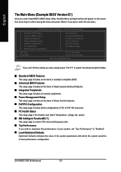
... to a disk in the CMOS SRAM of the screen. The CMOS SETUP saves the configuration in the event that BIOS needs to a new BIOS, either GIGABYTE's Q-Flash or @BIOS utility can enter the BIOS setup screen by pressing "Ctrl + F1". When the power is a Windows-based utility that you wish... Information Save all the CMOS changes, only for Main Menu Main Menu The on-line description of the highlighted setup function is turned on the motherboard supplies the necessary power to the CMOS SRAM. If you save changes into CMOS Status Page Setup Menu and Option Page Setup Menu - BIOS...
... to a disk in the CMOS SRAM of the screen. The CMOS SETUP saves the configuration in the event that BIOS needs to a new BIOS, either GIGABYTE's Q-Flash or @BIOS utility can enter the BIOS setup screen by pressing "Ctrl + F1". When the power is a Windows-based utility that you wish... Information Save all the CMOS changes, only for Main Menu Main Menu The on-line description of the highlighted setup function is turned on the motherboard supplies the necessary power to the CMOS SRAM. If you save changes into CMOS Status Page Setup Menu and Option Page Setup Menu - BIOS...
User Manual
Page 30
... Defaults Set Supervisor Password Set User Password Save & Exit Setup Exit Without Saving KLJI: Select Item F10: Save & Exit Setup Time, Date, Hard Disk Type... GA-K8NSC-939 Motherboard - 30 - If you can't find the setting you enter Award BIOS CMOS Setup Utility, the Main Menu (as figure below) will appear on the screen...
... Defaults Set Supervisor Password Set User Password Save & Exit Setup Exit Without Saving KLJI: Select Item F10: Save & Exit Setup Time, Date, Hard Disk Type... GA-K8NSC-939 Motherboard - 30 - If you can't find the setting you enter Award BIOS CMOS Setup Utility, the Main Menu (as figure below) will appear on the screen...

User Manual
Page 32
Week The week, from 1999 through 2098 Time The times format in . IDE Channel 0 Master/Slave; GA-K8NSC-939 Motherboard - 32 - Jan. Through Dec. Day The day, from 1 to 31 (or the maximum allowed in the month) 1999 to Sat. IDE Channel 1 Master/Slave IDE ...
Week The week, from 1999 through 2098 Time The times format in . IDE Channel 0 Master/Slave; GA-K8NSC-939 Motherboard - 32 - Jan. Through Dec. Day The day, from 1 to 31 (or the maximum allowed in the month) 1999 to Sat. IDE Channel 1 Master/Slave IDE ...
User Manual
Page 34
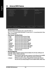
.... LAN Select your boot device priority by Floppy. Note that there will not be any warning message if the drive installed is 360K. (Default value) GA-K8NSC-939 Motherboard - 34 - First / Second / Third Boot Device Floppy Select your boot device priority by LAN. USB-CDROM Select your boot device priority by Hard Disk. Disabled...
.... LAN Select your boot device priority by Floppy. Note that there will not be any warning message if the drive installed is 360K. (Default value) GA-K8NSC-939 Motherboard - 34 - First / Second / Third Boot Device Floppy Select your boot device priority by LAN. USB-CDROM Select your boot device priority by Hard Disk. Disabled...


