User Manual
Page 4
Table of Contents ItemChecklist ...6 OptionalAccessories ...6 GA-K8N51GMF/GA-K8N51GMF-RH Motherboard Layout 7 Block Diagram ...8 Chapter 1 Hardware Installation 9 1-1 Considerations Prior to Installation 9 1-2 Feature Summary 10 1-3 Installation of the CPU and Heatsink 12 1-3-1 Installation of the CPU 12 1-3-2 ...
Table of Contents ItemChecklist ...6 OptionalAccessories ...6 GA-K8N51GMF/GA-K8N51GMF-RH Motherboard Layout 7 Block Diagram ...8 Chapter 1 Hardware Installation 9 1-1 Considerations Prior to Installation 9 1-2 Feature Summary 10 1-3 Installation of the CPU and Heatsink 12 1-3-1 Installation of the CPU 12 1-3-2 ...

User Manual
Page 10
...; 1 front audio connector Š 1 CD In connector Š 2 USB 2.0/1.1 connectors for additional 4 USB 2.0/1.1 ports by cable Š 1 SPDIF In/Out connector Š 1 power LED connector GA-K8N51GMF(-RH) Motherboard - 10 - Line Out (Front Speaker Out) ; Center/Subwoofer Speaker Out ; Side Speaker Out connection Š SPDIF In/Out connection Š CD In connection IEEE 1394...
...; 1 front audio connector Š 1 CD In connector Š 2 USB 2.0/1.1 connectors for additional 4 USB 2.0/1.1 ports by cable Š 1 SPDIF In/Out connector Š 1 power LED connector GA-K8N51GMF(-RH) Motherboard - 10 - Line Out (Front Speaker Out) ; Center/Subwoofer Speaker Out ; Side Speaker Out connection Š SPDIF In/Out connection Š CD In connection IEEE 1394...
User Manual
Page 12
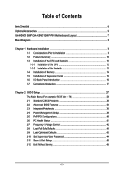
... to set the frequency beyond hardware specifications since it into its original position. The pin 1 location is installed on the socket and processor. GA-K8N51GMF(-RH) Motherboard - 12 - Align the processor to see that matches up to inserting the processor. Fig.2 Pin 1 location on the CPU prior to... with the following conditions: 1. Please take note of the CPU and gently press themetal lever back into position making sure that the motherboard supports the CPU. 2. Please make sure the heatsink is designated on the middle of the one finger down on the processor by ...
... to set the frequency beyond hardware specifications since it into its original position. The pin 1 location is installed on the socket and processor. GA-K8N51GMF(-RH) Motherboard - 12 - Align the processor to see that matches up to inserting the processor. Fig.2 Pin 1 location on the CPU prior to... with the following conditions: 1. Please take note of the CPU and gently press themetal lever back into position making sure that the motherboard supports the CPU. 2. Please make sure the heatsink is designated on the middle of the one finger down on the processor by ...

User Manual
Page 14
.... Before installing or removing memory modules, please make sure that the computer power is supported by the motherboard. Memory modules have a foolproof insertion design. If you wish to insert the module, please switch the direction. GA-K8N51GMF(-RH) Motherboard - 14 - The memory capacity used is switched off to lock the DIMM module. Reverse the installation...
.... Before installing or removing memory modules, please make sure that the computer power is supported by the motherboard. Memory modules have a foolproof insertion design. If you wish to insert the module, please switch the direction. GA-K8N51GMF(-RH) Motherboard - 14 - The memory capacity used is switched off to lock the DIMM module. Reverse the installation...

User Manual
Page 16
... IEEE1394 cable, please contact your device(s) such as USB keyboard, mouse, scanner, zip, speaker...etc. can be connected to this connector. have a standard USB interface. GA-K8N51GMF(-RH) Motherboard - 16 - Line Out (Front Speaker Out) Connect the stereo speakers, earphone or front surround speakers to Line In jack. Also make sure your local dealer...
... IEEE1394 cable, please contact your device(s) such as USB keyboard, mouse, scanner, zip, speaker...etc. can be connected to this connector. have a standard USB interface. GA-K8N51GMF(-RH) Motherboard - 16 - Line Out (Front Speaker Out) Connect the stereo speakers, earphone or front surround speakers to Line In jack. Also make sure your local dealer...

User Manual
Page 18
...supply enough stable power to start . Otherwise, please do not remove it. 42 31 Pin No. 1 2 3 4 Definition GND GND +12V +12V GA-K8N51GMF(-RH) Motherboard Pin No. It is unable to all components and devices are properly installed. The ATX_12V power connector mainly supplies power to handle the system voltage... system will not start . If you use a 24-pin ATX power supply, please remove the small cover on the power connector on the motherboard and connect tightly. If the ATX_12V power connector is used (300W or greater). English 1/2) ATX_12V / ATX (Power Connector) With the use of...
...supply enough stable power to start . Otherwise, please do not remove it. 42 31 Pin No. 1 2 3 4 Definition GND GND +12V +12V GA-K8N51GMF(-RH) Motherboard Pin No. It is unable to all components and devices are properly installed. The ATX_12V power connector mainly supplies power to handle the system voltage... system will not start . If you use a 24-pin ATX power supply, please remove the small cover on the power connector on the motherboard and connect tightly. If the ATX_12V power connector is used (300W or greater). English 1/2) ATX_12V / ATX (Power Connector) With the use of...
User Manual
Page 20
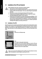
... the computer via an IDE connector. One IDE connector can then connect to work properly. 1 7 7 1 Pin No. 1 2 3 4 5 6 7 Definition GND TXP TXN GND RXN RXP GND GA-K8N51GMF(-RH) Motherboard - 20 - Please refer to the BIOS setting for information on settings, please refer to the instructions located on one IDE cable, and the single IDE...
... the computer via an IDE connector. One IDE connector can then connect to work properly. 1 7 7 1 Pin No. 1 2 3 4 5 6 7 Definition GND TXP TXN GND RXN RXP GND GA-K8N51GMF(-RH) Motherboard - 20 - Please refer to the BIOS setting for information on settings, please refer to the instructions located on one IDE cable, and the single IDE...
User Manual
Page 22
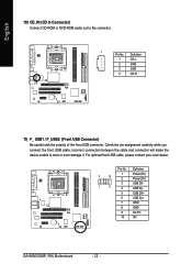
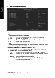
... work or even damage it. Definition 1 Power (5V) 2 10 2 Power (5V) 3 USB DX- 1 9 4 USB Dy- 5 USB DX+ 6 USB Dy+ 7 GND 8 GND 9 No Pin 10 NC GA-K8N51GMF(-RH) Motherboard - 22 - Definition 1 CD-L 2 GND 3 GND 4 CD-R 11) F_ USB1 / F_USB2 (Front USB Connector) Be careful with the polarity of the front USB connector. For optional...
... work or even damage it. Definition 1 Power (5V) 2 10 2 Power (5V) 3 USB DX- 1 9 4 USB Dy- 5 USB DX+ 6 USB Dy+ 7 GND 8 GND 9 No Pin 10 NC GA-K8N51GMF(-RH) Motherboard - 22 - Definition 1 CD-L 2 GND 3 GND 4 CD-R 11) F_ USB1 / F_USB2 (Front USB Connector) Be careful with the polarity of the front USB connector. For optional...

User Manual
Page 24
Replace only with the same or equivalent type recommended by this jumper. 1 Open: Normal 1 Short: Clear CMOS 15) BATTERY GA-K8N51GMF(-RH) Motherboard Danger of used batteries according to its default values by the manufacturer. Plug the power cord in the battery holder to prevent from improper use a ...
Replace only with the same or equivalent type recommended by this jumper. 1 Open: Normal 1 Short: Clear CMOS 15) BATTERY GA-K8N51GMF(-RH) Motherboard Danger of used batteries according to its default values by the manufacturer. Plug the power cord in the battery holder to prevent from improper use a ...

User Manual
Page 28
...Set User Password Save & Exit Setup Exit Without Saving KLJI: Select Item F10: Save & Exit Setup Time, Date, Hard Disk Type... GA-K8N51GMF(-RH) Motherboard - 28 - This action makes the system reset to exit this chapter are for reference only and may differ from the exact settings for... onboard (or add-on the screen. English : For Boot Menu Select boot sequence for your motherboard. GA-K8N51GMF-RH F4 . . . . :BIOS Setup/Q-Flash, : Xpress Recovery2, For Boot Menu 01/16/2006-C51-MCP51-6A61HG0BC-00 For Boot Menu Use < > or ...
...Set User Password Save & Exit Setup Exit Without Saving KLJI: Select Item F10: Save & Exit Setup Time, Date, Hard Disk Type... GA-K8N51GMF(-RH) Motherboard - 28 - This action makes the system reset to exit this chapter are for reference only and may differ from the exact settings for... onboard (or add-on the screen. English : For Boot Menu Select boot sequence for your motherboard. GA-K8N51GMF-RH F4 . . . . :BIOS Setup/Q-Flash, : Xpress Recovery2, For Boot Menu 01/16/2006-C51-MCP51-6A61HG0BC-00 For Boot Menu Use < > or ...
User Manual
Page 30
..." to select this to automatically detect IDE devices during POST(default) None Select this if no IDE devices are : CHS/LBA/Large/Auto(default:Auto) GA-K8N51GMF(-RH) Motherboard - 30 - You can manually input the correct settings Access Mode Use this option for the hard drive. Through Dec. time clock. The time is 13...
..." to select this to automatically detect IDE devices during POST(default) None Select this if no IDE devices are : CHS/LBA/Large/Auto(default:Auto) GA-K8N51GMF(-RH) Motherboard - 30 - You can manually input the correct settings Access Mode Use this option for the hard drive. Through Dec. time clock. The time is 13...
User Manual
Page 32
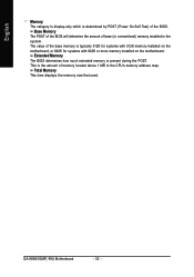
... base (or conventional) memory installed in the CPU's memory address map. Extended Memory The BIOS determines how much extended memory is present during the POST. GA-K8N51GMF(-RH) Motherboard - 32 - Base Memory The POST of the BIOS will determine the amount of memory located above 1 MB in the system. The value of the BIOS...-only which is determined by POST (Power On Self Test) of the base memory is typically 512K for systems with 512K memory installed on the motherboard, or 640K for systems with 640K or more memory installed on the...
... base (or conventional) memory installed in the CPU's memory address map. Extended Memory The BIOS determines how much extended memory is present during the POST. GA-K8N51GMF(-RH) Motherboard - 32 - Base Memory The POST of the BIOS will determine the amount of memory located above 1 MB in the system. The value of the BIOS...-only which is determined by POST (Power On Self Test) of the base memory is typically 512K for systems with 512K memory installed on the motherboard, or 640K for systems with 640K or more memory installed on the...
User Manual
Page 34
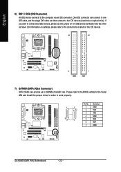
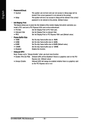
... a graphics card on the PCI Express slot. (Default value) Always Enable Onboard GPU will always be enabled whether there is not entered at the prompt. GA-K8N51GMF(-RH) Motherboard - 34 - PEG Set Init Display First to PCI Express VGA card.(Default value) Frame Buffer Size 16MB Set On-chip frame buffer size to 16MB... System The system can not boot and can not access to Setup page will be denied if the correct password is a graphics card on the motherboard. PCI Slot Set Init Display First to PCI VGA card.
... a graphics card on the PCI Express slot. (Default value) Always Enable Onboard GPU will always be enabled whether there is not entered at the prompt. GA-K8N51GMF(-RH) Motherboard - 34 - PEG Set Init Display First to PCI Express VGA card.(Default value) Frame Buffer Size 16MB Set On-chip frame buffer size to 16MB... System The system can not boot and can not access to Setup page will be denied if the correct password is a graphics card on the motherboard. PCI Slot Set Init Display First to PCI VGA card.
User Manual
Page 36
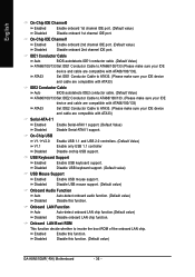
...). Onboard LAN Function Auto Auto-detect onboard LAN chip function.(Default value) Disabled Disable onboard LAN chip function. Enabled Disabled Enable this function. (Default value) GA-K8N51GMF(-RH) Motherboard - 36 - ATA33 Set IDE1 Conductor Cable to ATA33. (Please make sure your IDE device and cable are compatible with ATA33) IDE2 Conductor Cable Auto BIOS...
...). Onboard LAN Function Auto Auto-detect onboard LAN chip function.(Default value) Disabled Disable onboard LAN chip function. Enabled Disabled Enable this function. (Default value) GA-K8N51GMF(-RH) Motherboard - 36 - ATA33 Set IDE1 Conductor Cable to ATA33. (Please make sure your IDE device and cable are compatible with ATA33) IDE2 Conductor Cable Auto BIOS...

User Manual
Page 38
... AC BACK Function [S1(POS)] [Instant-off . Soft-Off by Alarm x Day of Month Alarm : Everyday, 1~31 Time (hh: mm: ss) Alarm : (0~23) : (0~59) : (0~59) GA-K8N51GMF(-RH) Motherboard - 38 -
... AC BACK Function [S1(POS)] [Instant-off . Soft-Off by Alarm x Day of Month Alarm : Everyday, 1~31 Time (hh: mm: ss) Alarm : (0~23) : (0~59) : (0~59) GA-K8N51GMF(-RH) Motherboard - 38 -

User Manual
Page 40
GA-K8N51GMF(-RH) Motherboard - 40 - Auto assign IRQ to PCI 2. (Default value) Set IRQ 3,4,5,7,9,10,11,12,14,15 to PCI 1. English 2-5 PnP/PCI Configurations CMOS Setup Utility-Copyright (C) ...
GA-K8N51GMF(-RH) Motherboard - 40 - Auto assign IRQ to PCI 2. (Default value) Set IRQ 3,4,5,7,9,10,11,12,14,15 to PCI 1. English 2-5 PnP/PCI Configurations CMOS Setup Utility-Copyright (C) ...
User Manual
Page 42
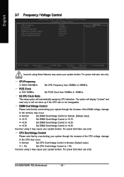
.... +0.2V Set DIMM OverVoltage Control to +0.2V. +0.3V Set DIMM OverVoltage Control to 145MHz. CPU OverVoltage Control Please note that by overclocking your system broken. GA-K8N51GMF(-RH) Motherboard - 42 - For power End-User use only! For power End-User use only! Incorrect using it may cause your system broken. DIMM OverVoltage Control Please...
.... +0.2V Set DIMM OverVoltage Control to +0.2V. +0.3V Set DIMM OverVoltage Control to 145MHz. CPU OverVoltage Control Please note that by overclocking your system broken. GA-K8N51GMF(-RH) Motherboard - 42 - For power End-User use only! For power End-User use only! Incorrect using it may cause your system broken. DIMM OverVoltage Control Please...

User Manual
Page 44
... enabled, the Supervisor password is required for the password every time the system is disabled, the system will boot and you can enter Setup freely. GA-K8N51GMF(-RH) Motherboard - 44 - Once the password is rebooted or any time you try to enter Setup. The BIOS Setup program allows you to confirm the password being...
... enabled, the Supervisor password is required for the password every time the system is disabled, the system will boot and you can enter Setup freely. GA-K8N51GMF(-RH) Motherboard - 44 - Once the password is rebooted or any time you try to enter Setup. The BIOS Setup program allows you to confirm the password being...

User Manual
Page 48
GA-K8N51GMF(-RH) Motherboard - 48 - English 3-2 Software Application This page displays all the tools that Gigabyte developed and some free software, you can choose anyone you want and press "install" to install them. 3-3 Software Information This page lists the contents of software and drivers in this CD-title.
GA-K8N51GMF(-RH) Motherboard - 48 - English 3-2 Software Application This page displays all the tools that Gigabyte developed and some free software, you can choose anyone you want and press "install" to install them. 3-3 Software Information This page lists the contents of software and drivers in this CD-title.

User Manual
Page 52
and M.I .B.2 3. Help button 11. Function display LEDs 9. Overclocking 2. GIGABYTE Logo 10. GA-K8N51GMF(-RH) Motherboard - 52 - GO 6. "Easy Mode" & "Advance Mode" 7. Display screen 8. for special enhancement for CPU and Memory, 3) Smart-Fan ... Confirmation and Execution button Toggles between Easy and Advance Mode Display panel of CPU frequency Shows the current functions status Log on different motherboards. English 4-1-1 EasyTune 5 Introduction EasyTune 5 presents the most convenient Windows based system performance enhancement and manageability utility. PC Health 5. ...
and M.I .B.2 3. Help button 11. Function display LEDs 9. Overclocking 2. GIGABYTE Logo 10. GA-K8N51GMF(-RH) Motherboard - 52 - GO 6. "Easy Mode" & "Advance Mode" 7. Display screen 8. for special enhancement for CPU and Memory, 3) Smart-Fan ... Confirmation and Execution button Toggles between Easy and Advance Mode Display panel of CPU frequency Shows the current functions status Log on different motherboards. English 4-1-1 EasyTune 5 Introduction EasyTune 5 presents the most convenient Windows based system performance enhancement and manageability utility. PC Health 5. ...


