
User Manual
Page 1
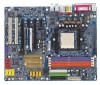
GA-K8N Ultra-SLI / GA-K8N Pro-SLI / GA-K8N-SLI AMD Socket 939 Processor Motherboard User's Manual Rev. 1004 12ME-K8NUSLI-1004
GA-K8N Ultra-SLI / GA-K8N Pro-SLI / GA-K8N-SLI AMD Socket 939 Processor Motherboard User's Manual Rev. 1004 12ME-K8NUSLI-1004
User Manual
Page 6
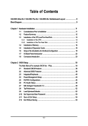
... Contents GA-K8N Ultra-SLI / GA-K8N Pro-SLI / GA-K8N-SLI Motherboard Layout 8 Block Diagram ...9 Chapter 1 Hardware Installation 11 1-1 Considerations Prior to Installation 11 1-2 Feature Summary 12 1-3 Installation of the CPU and Fan Heat Sink 14 1-3-1 Installation of the CPU 14 1-3-2 Installation of the Fan Heat Sink 15 1-4 Installation of Memory 16 1-5 Installation of Expansion Cards 18 1-6 Setup of SLI (Scalable...
... Contents GA-K8N Ultra-SLI / GA-K8N Pro-SLI / GA-K8N-SLI Motherboard Layout 8 Block Diagram ...9 Chapter 1 Hardware Installation 11 1-1 Considerations Prior to Installation 11 1-2 Feature Summary 12 1-3 Installation of the CPU and Fan Heat Sink 14 1-3-1 Installation of the CPU 14 1-3-2 Installation of the Fan Heat Sink 15 1-4 Installation of Memory 16 1-5 Installation of Expansion Cards 18 1-6 Setup of SLI (Scalable...
User Manual
Page 11
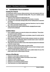
... the electronic components, please have a problem related to the use exceeding the permitted parameters. 6. To prevent damage to the motherboard, please do not remove the stickers on top of an antistatic pad or within the computer casing. 6. English Chapter 1 Hardware... sure there are required for warranty validation. 2. When handling the motherboard, avoid touching any installation steps or have these items on the motherboard. Instances of uncertified components. 5. Damage due to be an unofficial Gigabyte product. - 11 - Product determined to use of Non-Warranty ...
... the electronic components, please have a problem related to the use exceeding the permitted parameters. 6. To prevent damage to the motherboard, please do not remove the stickers on top of an antistatic pad or within the computer casing. 6. English Chapter 1 Hardware... sure there are required for warranty validation. 2. When handling the motherboard, avoid touching any installation steps or have these items on the motherboard. Instances of uncertified components. 5. Damage due to be an unofficial Gigabyte product. - 11 - Product determined to use of Non-Warranty ...
User Manual
Page 12
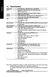
... is reserved for system usage and therefore the actual memory size is less than the stated amount. Surround Speaker Out (Rear Speaker Out) ; Only for GA-K8N Ultra-SLI. K8 nForce4 SLI Series Motherboard - 12 - MIC ; For example, 4 GB of memory size will instead be shown as 3.xxGB memory during system startup. Only for...
... is reserved for system usage and therefore the actual memory size is less than the stated amount. Surround Speaker Out (Rear Speaker Out) ; Only for GA-K8N Ultra-SLI. K8 nForce4 SLI Series Motherboard - 12 - MIC ; For example, 4 GB of memory size will instead be shown as 3.xxGB memory during system startup. Only for...
User Manual
Page 13
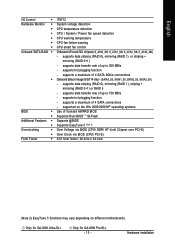
... Onboard Silicon Image SiI3114 chip (SATA0_SII, SATA1_SII, SATA2_SII, SATA3_SII) - Only for GA-K8N Pro-SLI. - 13 - supports hot plugging function - Hardware Installation supports a maximum of 4 SATA connections - Only for GA-K8N Ultra-SLI. supports data transfer rate of up to 300 MB/s - supports data striping (...Clock via BIOS (CPU/ PCI-E) ATX form factor; 30.5cm x 24.4cm (Note 2) EasyTune 5 functions may vary depending on different motherboards. English I/O Control Š Hardware Monitor Š Š Š Š Š Š Onboard SATA RAID Š Š...
... Onboard Silicon Image SiI3114 chip (SATA0_SII, SATA1_SII, SATA2_SII, SATA3_SII) - Only for GA-K8N Pro-SLI. - 13 - supports hot plugging function - Hardware Installation supports a maximum of 4 SATA connections - Only for GA-K8N Ultra-SLI. supports data transfer rate of up to 300 MB/s - supports data striping (...Clock via BIOS (CPU/ PCI-E) ATX form factor; 30.5cm x 24.4cm (Note 2) EasyTune 5 functions may vary depending on different motherboards. English I/O Control Š Hardware Monitor Š Š Š Š Š Š Onboard SATA RAID Š Š...
User Manual
Page 14
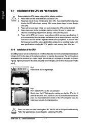
...1. Align the processor to a triangle on the socket as shown in Figure 2. Gently place the CPU into position making sure that the motherboard supports the CPU. 2. The CPU will not insert properly. Please make sure the fan heat sink is positioned into its original position. ...perfectly into their holes. Move the socket lever to the unlocked position as shown in Figure 1.(90o to inserting the processor. K8 nForce4 SLI Series Motherboard - 14 - It is designated on the socket and processor. English 1-3 Installation of the CPU and gently press the metal lever ...
...1. Align the processor to a triangle on the socket as shown in Figure 2. Gently place the CPU into position making sure that the motherboard supports the CPU. 2. The CPU will not insert properly. Please make sure the fan heat sink is positioned into its original position. ...perfectly into their holes. Move the socket lever to the unlocked position as shown in Figure 1.(90o to inserting the processor. K8 nForce4 SLI Series Motherboard - 14 - It is designated on the socket and processor. English 1-3 Installation of the CPU and gently press the metal lever ...

User Manual
Page 15
... of the Fan Heat Sink Fig.1 Before installing the CPU fan heat sink, please first add an even layer of heat sink paste on the motherboard so that either thermal tape rather than heat sink paste be used for detailed installation instructions). Install all the fan heat sink components (Please refer...
... of the Fan Heat Sink Fig.1 Before installing the CPU fan heat sink, please first add an even layer of heat sink paste on the motherboard so that either thermal tape rather than heat sink paste be used for detailed installation instructions). Install all the fan heat sink components (Please refer...

User Manual
Page 16
... inserted only in only one direction. Before installing or removing memory modules, please make sure that the computer power is supported by the motherboard. Memory modules are unable to prevent hardware damage. 3. Then push it down. Reverse the installation steps when you are designed so that... 1. Notch DDR Fig.1 The DIMM socket has a notch, so the DIMM memory module can be installed in one direction. K8 nForce4 SLI Series Motherboard - 16 - It is recommended that they can only fit in one direction. Memory modules have a foolproof insertion design. The...
... inserted only in only one direction. Before installing or removing memory modules, please make sure that the computer power is supported by the motherboard. Memory modules are unable to prevent hardware damage. 3. Then push it down. Reverse the installation steps when you are designed so that... 1. Notch DDR Fig.1 The DIMM socket has a notch, so the DIMM memory module can be installed in one direction. K8 nForce4 SLI Series Motherboard - 16 - It is recommended that they can only fit in one direction. Memory modules have a foolproof insertion design. The...
User Manual
Page 18
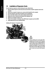
Power on the card are indeed seated in motherboard. 4. Press the expansion card firmly into the computer. 2. Replace the screw to secure the slot bracket of the PCI Express x 16 slot when you try ...: 1. Read the related expansion card's instruction document before install the expansion card into expansion slot in the slot. 5. Install related driver from BIOS. 8. K8 nForce4 SLI Series Motherboard - 18 - English 1-5 Installation of Expansion Cards You can install your expansion card by the small white-drawable bar.
Power on the card are indeed seated in motherboard. 4. Press the expansion card firmly into the computer. 2. Replace the screw to secure the slot bracket of the PCI Express x 16 slot when you try ...: 1. Read the related expansion card's instruction document before install the expansion card into expansion slot in the slot. 5. Install related driver from BIOS. 8. K8 nForce4 SLI Series Motherboard - 18 - English 1-5 Installation of Expansion Cards You can install your expansion card by the small white-drawable bar.

User Manual
Page 19
...socket with the gold edge connector on the GA-K8N Ulra-SLI/GA-K8N Pro-SLI/GA-K8N-SLI motherboard. Installing a device to provide enhanced performance. We do not recommend removing the SLI switch module from the motherboard because in two modes. SLI Mode: In SLI Mode, the two PCIE x 16 slots ... them as a PCIE x 8 slot. Together, the NVIDIA SLI technologies work and deliver heartpounding PC performance. Understanding the GIGABYTE SLI switch module: You can find an SLI switch module socket inserted with an SLI switch SLI Mode module between the first and second PCIE x 16 slots...
...socket with the gold edge connector on the GA-K8N Ulra-SLI/GA-K8N Pro-SLI/GA-K8N-SLI motherboard. Installing a device to provide enhanced performance. We do not recommend removing the SLI switch module from the motherboard because in two modes. SLI Mode: In SLI Mode, the two PCIE x 16 slots ... them as a PCIE x 8 slot. Together, the NVIDIA SLI technologies work and deliver heartpounding PC performance. Understanding the GIGABYTE SLI switch module: You can find an SLI switch module socket inserted with an SLI switch SLI Mode module between the first and second PCIE x 16 slots...
User Manual
Page 20
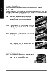
...K8 nForce4 SLI Series Motherboard - 20 - Align the small notch at a 25o angle. Step 4: Gently press down on the two ends of the module with the key in place by the socket clips. (You should hear a "click" when the module is currrently supported by the NVIDIA SLI technology. Step 2: Position the SLI Mode ...Installation of the socket and the module may then be removed from the socket. Step 3: Insert the top edge of the same model to enable SLI Mode. Step 1: Gently spread the retaining clips of Expansion Cards" on your system is to take out the module from the socket and insert ...
...K8 nForce4 SLI Series Motherboard - 20 - Align the small notch at a 25o angle. Step 4: Gently press down on the two ends of the module with the key in place by the socket clips. (You should hear a "click" when the module is currrently supported by the NVIDIA SLI technology. Step 2: Position the SLI Mode ...Installation of the socket and the module may then be removed from the socket. Step 3: Insert the top edge of the same model to enable SLI Mode. Step 1: Gently spread the retaining clips of Expansion Cards" on your system is to take out the module from the socket and insert ...

User Manual
Page 21
...bracket Step 4: Plug the display cable into either one of the bridge connector. If you click Apply. Then the SLI configuration is completed. - 21 - curely fit onto the SLI gold edge connetors of both cards. Female slots on the bridge connector Gold edge connector on the top of graphics...place this part on the top of the two graphics cards for display output. if you must install the retention bracket included with the motherboard and secure the retention bracket to the chassis back panel with a screw. Graphics Card Driver Setting: Step 1: After installing graphics card ...
...bracket Step 4: Plug the display cable into either one of the bridge connector. If you click Apply. Then the SLI configuration is completed. - 21 - curely fit onto the SLI gold edge connetors of both cards. Female slots on the bridge connector Gold edge connector on the top of graphics...place this part on the top of the two graphics cards for display output. if you must install the retention bracket included with the motherboard and secure the retention bracket to the chassis back panel with a screw. Graphics Card Driver Setting: Step 1: After installing graphics card ...

User Manual
Page 22
...(s), please make sure your device has digital output function. If your OS does not support USB controller, please contact OS vendor for GA-K8N Ultra-SLI. can be connected to MIC In jack. have a standard USB interface. For more information please contact your device(s) such as USB...upgrade. LAN Port 1 The provided Internet connection is Gigabit Ethernet, providing data transfer speeds of 10/100/1000Mbps. K8 nForce4 SLI Series Motherboard - 22 - Parallel Port The parallel port allows connection of providing digital audio to external speakers or compressed AC3 data to the...
...(s), please make sure your device has digital output function. If your OS does not support USB controller, please contact OS vendor for GA-K8N Ultra-SLI. can be connected to MIC In jack. have a standard USB interface. For more information please contact your device(s) such as USB...upgrade. LAN Port 1 The provided Internet connection is Gigabit Ethernet, providing data transfer speeds of 10/100/1000Mbps. K8 nForce4 SLI Series Motherboard - 22 - Parallel Port The parallel port allows connection of providing digital audio to external speakers or compressed AC3 data to the...
User Manual
Page 24
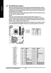
..., the result can supply enough stable power to all components and devices are properly installed. Align the power connector with its proper location on the motherboard before plugging in the power cord ; Definition 1 3.3V 13 3.3V 2 3.3V 14 -12V 3 GND 15 GND 4 +5V 16 PS_ON(soft On/...11 +12V(Onlyfor24-pinATX) 23 +5V (Only for 24-pin ATX) 12 3.3V(Onlyfor24-pinATX) 24 GND(Only for 24-pin ATX) K8 nForce4 SLI Series Motherboard - 24 - If the ATX_12V power connector is recommended that a power supply that is unable to start . Pin No. Definition Pin No. Caution!...
..., the result can supply enough stable power to all components and devices are properly installed. Align the power connector with its proper location on the motherboard before plugging in the power cord ; Definition 1 3.3V 13 3.3V 2 3.3V 14 -12V 3 GND 15 GND 4 +5V 16 PS_ON(soft On/...11 +12V(Onlyfor24-pinATX) 23 +5V (Only for 24-pin ATX) 12 3.3V(Onlyfor24-pinATX) 24 GND(Only for 24-pin ATX) K8 nForce4 SLI Series Motherboard - 24 - If the ATX_12V power connector is recommended that a power supply that is unable to start . Pin No. Definition Pin No. Caution!...
User Manual
Page 26
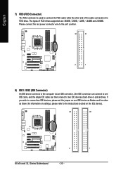
...) The FDD connector is used to connect the FDD cable while the other as Slave (for information on the IDE device). 40 39 2 1 K8 nForce4 SLI Series Motherboard - 26 - Please connect the red power connector wire to the pin1 position. 34 33 2 1 8) IDE1 / IDE2 (IDE Connector) An IDE device connects to the...
...) The FDD connector is used to connect the FDD cable while the other as Slave (for information on the IDE device). 40 39 2 1 K8 nForce4 SLI Series Motherboard - 26 - Please connect the red power connector wire to the pin1 position. 34 33 2 1 8) IDE1 / IDE2 (IDE Connector) An IDE device connects to the...
User Manual
Page 28
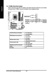
.... Pin 3: NC Pin 4: Data(-) Open: Normal Close: Reset Hardware System Open: Normal Close: Power On/Off Pin 1: LED anode(+) Pin 2: LED cathode(-) NC K8 nForce4 SLI Series Motherboard - 28 - Speaker Connector Power Switch Message LED/ Power/ Sleep LED SPEAK- 20 19 SPEAK+ PWPW+ MSGMSG+ 21 NCRES+ RES-
.... Pin 3: NC Pin 4: Data(-) Open: Normal Close: Reset Hardware System Open: Normal Close: Power On/Off Pin 1: LED anode(+) Pin 2: LED cathode(-) NC K8 nForce4 SLI Series Motherboard - 28 - Speaker Connector Power Switch Message LED/ Power/ Sleep LED SPEAK- 20 19 SPEAK+ PWPW+ MSGMSG+ 21 NCRES+ RES-
User Manual
Page 30
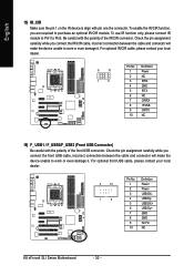
... contact your local dealer. 2 10 1 9 Pin No. 1 2 3 4 5 6 7 8 9 10 Definition Power Power USB DXUSB DyUSB DX+ USB Dy+ GND GND No Pin NC K8 nForce4 SLI Series Motherboard - 30 - Be careful with pin one the connector. To use IR function only, please connect IR module to Pin1 to purchase an optional IR/CIR...
... contact your local dealer. 2 10 1 9 Pin No. 1 2 3 4 5 6 7 8 9 10 Definition Power Power USB DXUSB DyUSB DX+ USB Dy+ GND GND No Pin NC K8 nForce4 SLI Series Motherboard - 30 - Be careful with pin one the connector. To use IR function only, please connect IR module to Pin1 to purchase an optional IR/CIR...
User Manual
Page 32
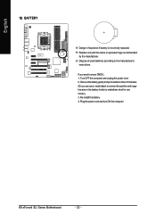
... connect the positive and negative pins in the battery holder to makethem short for about 10 minutes. (Or you want to erase CMOS... 1. K8 nForce4 SLI Series Motherboard - 32 - Take out the battery gently and put it aside for one minute.) 3. Re-install the battery. 4. Dispose of explosion if battery is incorrectly...
... connect the positive and negative pins in the battery holder to makethem short for about 10 minutes. (Or you want to erase CMOS... 1. K8 nForce4 SLI Series Motherboard - 32 - Take out the battery gently and put it aside for one minute.) 3. Re-install the battery. 4. Dispose of explosion if battery is incorrectly...
User Manual
Page 33
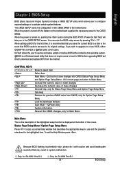
... either GIGABYTE's Q-Flash or @BIOS utility can enter the BIOS setup screen by pressing "Ctrl + F1". You can be reset to a disk in the event that may result in the CMOS SRAM of the screen. If you wish to upgrade to the CMOS SETUP screen. Only for GA-K8N Pro-SLI. -...the motherboard supplies the necessary power to DOS before upgrading BIOS but directly download and update BIOS from CMOS, only for Option Page Setup Menu Load the Optimized Defaults Dual BIOS /Q-Flash utility System Information Save all the CMOS changes, only for the highlighted item. Only for GA-K8N Ultra-SLI....
... either GIGABYTE's Q-Flash or @BIOS utility can enter the BIOS setup screen by pressing "Ctrl + F1". You can be reset to a disk in the event that may result in the CMOS SRAM of the screen. If you wish to upgrade to the CMOS SETUP screen. Only for GA-K8N Pro-SLI. -...the motherboard supplies the necessary power to DOS before upgrading BIOS but directly download and update BIOS from CMOS, only for Option Page Setup Menu Load the Optimized Defaults Dual BIOS /Q-Flash utility System Information Save all the CMOS changes, only for the highlighted item. Only for GA-K8N Ultra-SLI....

User Manual
Page 34
... Hard Disk Type... Use arrow keys to select among the items and press to maximize the performance of your motherboard. CMOS Setup Utility-Copyright (C) 1984-2005 Award Software Standard CMOS Features Advanced BIOS Features Integrated Peripherals Power Management ...you enter Award BIOS CMOS Setup Utility, the Main Menu (as figure below) will appear on the screen. K8 nForce4 SLI Series Motherboard - 34 - The Main Menu (For example: BIOS Ver. : F6a) Once you wish to accept or enter ...for reference only and may differ from the exact settings for GA-K8N Ultra-SLI. Only for GA-K8N Pro-SLI.
... Hard Disk Type... Use arrow keys to select among the items and press to maximize the performance of your motherboard. CMOS Setup Utility-Copyright (C) 1984-2005 Award Software Standard CMOS Features Advanced BIOS Features Integrated Peripherals Power Management ...you enter Award BIOS CMOS Setup Utility, the Main Menu (as figure below) will appear on the screen. K8 nForce4 SLI Series Motherboard - 34 - The Main Menu (For example: BIOS Ver. : F6a) Once you wish to accept or enter ...for reference only and may differ from the exact settings for GA-K8N Ultra-SLI. Only for GA-K8N Pro-SLI.


