User Guide
Page 1
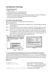
.... (1 GB=1024 MB. After entering all of the commands, be used to create the store partition. At the diskpart prompt, type the following commands in BIOS Setup 4.
.... (1 GB=1024 MB. After entering all of the commands, be used to create the store partition. At the diskpart prompt, type the following commands in BIOS Setup 4.
User Guide
Page 2
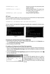
...(Figure 4): DISKPART>set when to copy and move the data from the memory to the SSD after completing the commands above. The Timer slider in BIOS Setup 1. Figure 3 Figure 4 D. When the system restarts, press to the results from Start\All Programs\Intel or click the icon in the ...D3BFE2DE-3DAF-11DF-BA40-E3A556D89593 You have created the Intel Rapid Start Technology store partition after entering S3 mode. Save the settings and exit BIOS Setup. While in the notification area. After the installation is volume of the selected disk and the volumes on that you to enable...
...(Figure 4): DISKPART>set when to copy and move the data from the memory to the SSD after completing the commands above. The Timer slider in BIOS Setup 1. Figure 3 Figure 4 D. When the system restarts, press to the results from Start\All Programs\Intel or click the icon in the ...D3BFE2DE-3DAF-11DF-BA40-E3A556D89593 You have created the Intel Rapid Start Technology store partition after entering S3 mode. Save the settings and exit BIOS Setup. While in the notification area. After the installation is volume of the selected disk and the volumes on that you to enable...
User Guide
Page 3
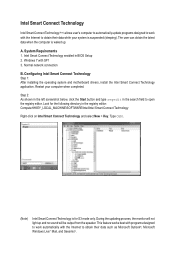
... user can obtain the latest data when the computer is suspended (sleeping). Type OEM. (Note) Intel Smart Connect Technology is for the following directory in BIOS Setup 2. System Requirements 1. During the updating process, the monitor will be output from the speaker. Windows 7 with the Internet to open the registry editor. Restart...
... user can obtain the latest data when the computer is suspended (sleeping). Type OEM. (Note) Intel Smart Connect Technology is for the following directory in BIOS Setup 2. System Requirements 1. During the updating process, the monitor will be output from the speaker. Windows 7 with the Internet to open the registry editor. Restart...
User Guide
Page 5
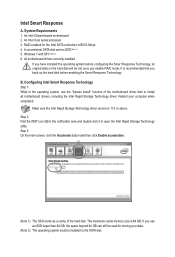
... the Intel Rapid Storage Technology driver version is 64 GB. Intel Smart Response A. System Requirements 1. Windows 7 with SP1 (Note 2) 6. B. Step 2: Find the IRST icon in BIOS Setup 4. The maximum cache memory size is 11.0 or above. RAID enabled for storing your computer when completed. Step 3: On the main screen, click the...
... the Intel Rapid Storage Technology driver version is 64 GB. Intel Smart Response A. System Requirements 1. Windows 7 with SP1 (Note 2) 6. B. Step 2: Find the IRST icon in BIOS Setup 4. The maximum cache memory size is 11.0 or above. RAID enabled for storing your computer when completed. Step 3: On the main screen, click the...
User Manual
Page 3
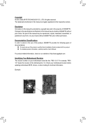
... Your Motherboard Revision The revision number on your motherboard revision before updating motherboard BIOS, drivers, or when looking for technical information. Check your motherboard looks like this product, GIGABYTE provides the following types of documentations: „„ For quick set-up...be reproduced, copied, translated, transmitted, or published in this manual may be made by any form or by GIGABYTE without GIGABYTE's prior written permission. Changes to the specifications and features in any means without prior notice. Documentation Classifications In order...
... Your Motherboard Revision The revision number on your motherboard revision before updating motherboard BIOS, drivers, or when looking for technical information. Check your motherboard looks like this product, GIGABYTE provides the following types of documentations: „„ For quick set-up...be reproduced, copied, translated, transmitted, or published in this manual may be made by any form or by GIGABYTE without GIGABYTE's prior written permission. Changes to the specifications and features in any means without prior notice. Documentation Classifications In order...
User Manual
Page 4
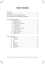
Table of Contents Box Contents...6 Optional Items...6 GA-Z77-DS3H/GA-H77-DS3H Motherboard Layout 7 GA-Z77-DS3H/GA-H77-DS3H Motherboard Block Diagram 8 Chapter 1 Hardware Installation 9 1-1 Installation Precautions 9 1-2 Product Specifications 10 1-3 Installing the CPU and CPU... Installing a Memory 17 1-5 Installing an Expansion Card 18 1-6 Back Panel Connectors 19 1-7 Internal Connectors 21 Chapter 2 BIOS Setup 31 2-1 Startup Screen 32 2-2 The Main Menu 33 2-3 M.I.T...35 2-4 System...43 2-5 BIOS Features 44 2-6 Peripherals...46 2-7 Power Management 50 2-8 Save & Exit...52 - 4 -
Table of Contents Box Contents...6 Optional Items...6 GA-Z77-DS3H/GA-H77-DS3H Motherboard Layout 7 GA-Z77-DS3H/GA-H77-DS3H Motherboard Block Diagram 8 Chapter 1 Hardware Installation 9 1-1 Installation Precautions 9 1-2 Product Specifications 10 1-3 Installing the CPU and CPU... Installing a Memory 17 1-5 Installing an Expansion Card 18 1-6 Back Panel Connectors 19 1-7 Internal Connectors 21 Chapter 2 BIOS Setup 31 2-1 Startup Screen 32 2-2 The Main Menu 33 2-3 M.I.T...35 2-4 System...43 2-5 BIOS Features 44 2-6 Peripherals...46 2-7 Power Management 50 2-8 Save & Exit...52 - 4 -
User Manual
Page 5
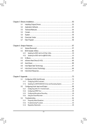
... 54 3-4 Contact...55 3-5 System...55 3-6 Download Center 56 3-7 New Program 56 Chapter 4 Unique Features 57 4-1 Xpress Recovery2 57 4-2 BIOS Update Utilities 60 4-2-1 Updating the BIOS with the Q-Flash Utility 60 4-2-2 Updating the BIOS with the @BIOS Utility 63 4-3 Q-Share...64 4-4 eXtreme Hard Drive (X.H.D 65 4-5 Auto Green...66 4-6 Intel Rapid Start Technology 67 4-7 Intel Smart...
... 54 3-4 Contact...55 3-5 System...55 3-6 Download Center 56 3-7 New Program 56 Chapter 4 Unique Features 57 4-1 Xpress Recovery2 57 4-2 BIOS Update Utilities 60 4-2-1 Updating the BIOS with the Q-Flash Utility 60 4-2-2 Updating the BIOS with the @BIOS Utility 63 4-3 Q-Share...64 4-4 eXtreme Hard Drive (X.H.D 65 4-5 Auto Green...66 4-6 Intel Rapid Start Technology 67 4-7 Intel Smart...
User Manual
Page 8
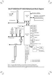
... PCI Express x1 Atheros GbE LAN x1 x4 x1 Intel® Z77j/ H77k PCI Express Bus x1 PCIe to USB 2.0 transfer speed. - 8 - k Only for GA-H77-DS3H. (Note 1) To support DDR3 1600 MHz, you must install an Intel 22nm (Ivy Bridge) CPU. (Note 2) In Windows XP, the Intel USB 3.0 ports can ...support up to PCI Bridge HDMI D-Sub Dual BIOS 2 SATA 6Gb/s 3 SATA 3Gb/s 1 mSATA 8 USB 2.0/1.1 PCI Bus CODEC 4 USB 3.0 (Note 2)/2.0 LPC Bus iTE COM Super I/O PS/2 KB/Mouse MIC (Center/Subwoofer ...
... PCI Express x1 Atheros GbE LAN x1 x4 x1 Intel® Z77j/ H77k PCI Express Bus x1 PCIe to USB 2.0 transfer speed. - 8 - k Only for GA-H77-DS3H. (Note 1) To support DDR3 1600 MHz, you must install an Intel 22nm (Ivy Bridge) CPU. (Note 2) In Windows XP, the Intel USB 3.0 ports can ...support up to PCI Bridge HDMI D-Sub Dual BIOS 2 SATA 6Gb/s 3 SATA 3Gb/s 1 mSATA 8 USB 2.0/1.1 PCI Bus CODEC 4 USB 3.0 (Note 2)/2.0 LPC Bus iTE COM Super I/O PS/2 KB/Mouse MIC (Center/Subwoofer ...
User Manual
Page 12
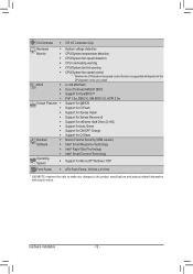
... will depend on the CPU/system cooler you install. 2 x 64 Mbit flash Use of licensed AMI EFI BIOS Support for DualBIOS™ PnP 1.0a, DMI 2.0, SM BIOS 2.6, ACPI 2.0a Support for @BIOS Support for Q-Flash Support for Xpress Install Support for Xpress Recovery2 Support for eXtreme Hard Drive (X.H.D) Support for ...Intel® Rapid Start Technology Intel® Smart Connect Technology Support for Microsoft® Windows 7/XP ATX Form Factor; 30.5cm x 21.5cm * GIGABYTE reserves the right to make any changes to the product specifications and product-related information without prior notice.
... will depend on the CPU/system cooler you install. 2 x 64 Mbit flash Use of licensed AMI EFI BIOS Support for DualBIOS™ PnP 1.0a, DMI 2.0, SM BIOS 2.6, ACPI 2.0a Support for @BIOS Support for Q-Flash Support for Xpress Install Support for Xpress Recovery2 Support for eXtreme Hard Drive (X.H.D) Support for ...Intel® Rapid Start Technology Intel® Smart Connect Technology Support for Microsoft® Windows 7/XP ATX Form Factor; 30.5cm x 21.5cm * GIGABYTE reserves the right to make any changes to the product specifications and product-related information without prior notice.
User Manual
Page 16
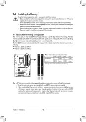
...Modules DDR3_4 - Dual Channel mode cannot be used and installed in the same colored DDR3 sockets. A memory module can be used . (Go to GIGABYTE's website for the latest supported memory speeds and memory modules.) •• Always turn off the computer and unplug the power cord from the power...in the DDR3_1 and DDR3_2 sockets. For optimum performance, when enabling Dual Channel mode with two or four memory modules, it is installed, the BIOS will double the original memory bandwidth. DS/SS DS/SS DDR3_2 DS/SS - The four DDR3 memory sockets are unable to insert the memory...
...Modules DDR3_4 - Dual Channel mode cannot be used and installed in the same colored DDR3 sockets. A memory module can be used . (Go to GIGABYTE's website for the latest supported memory speeds and memory modules.) •• Always turn off the computer and unplug the power cord from the power...in the DDR3_1 and DDR3_2 sockets. For optimum performance, when enabling Dual Channel mode with two or four memory modules, it is installed, the BIOS will double the original memory bandwidth. DS/SS DS/SS DDR3_2 DS/SS - The four DDR3 memory sockets are unable to insert the memory...
User Manual
Page 18
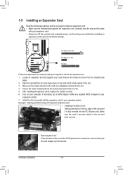
...;• Removing the Card: Press the latch at the end of the card until it is securely seated in the slot. 3. If necessary, go to BIOS Setup to install an expansion card: •• Make sure the motherboard supports the expansion card. Make sure the card is fully inserted into the... expansion card. •• Always turn off the computer and unplug the power cord from the power outlet before you begin to make any required BIOS changes for your expansion card(s). 7. After installing all expansion cards, replace the chassis cover(s). 6. Hardware Installation - 18 -
...;• Removing the Card: Press the latch at the end of the card until it is securely seated in the slot. 3. If necessary, go to BIOS Setup to install an expansion card: •• Make sure the motherboard supports the expansion card. Make sure the card is fully inserted into the... expansion card. •• Always turn off the computer and unplug the power cord from the power outlet before you begin to make any required BIOS changes for your expansion card(s). 7. After installing all expansion cards, replace the chassis cover(s). 6. Hardware Installation - 18 -
User Manual
Page 19
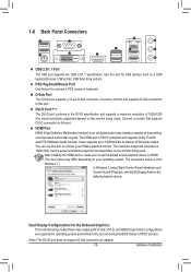
... audio/video interface capable of 1920x1200 (the actual resolutions supported depend on your HDMI-supported monitor. The screenshot below is 1920x1200, but not during the BIOS Setup or POST process. (Note) The DVI-D port does not support D-Sub connection by adapter. - 19 - PS/2 Keyboard/Mouse Port Use this port for the...
... audio/video interface capable of 1920x1200 (the actual resolutions supported depend on your HDMI-supported monitor. The screenshot below is 1920x1200, but not during the BIOS Setup or POST process. (Note) The DVI-D port does not support D-Sub connection by adapter. - 19 - PS/2 Keyboard/Mouse Port Use this port for the...
User Manual
Page 25
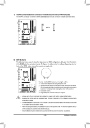
... 1 23 1 DIP 1 23 1 DIP 1 23 PCIe power connector (SATA)(X58A-OC) SMB_CPT (GA-IVB) CLR_CMOS CI DIS_ME GP15_CPT (GA-IVB) 8) BAT (Battery) The battery provides power to keep the values (such as BIOS configurations, daXtDeP, _aCnPdUtime information) er 3) in the CMOS when the computer is replaced with local environmental ... . Replace the battery when the batteX(GrDyAP-v_IVPoBClt)Hage drops to a single solid-state drive. BIOS_P (GA-IVB You may clear the CMOS values by the Intel Z77/H77 Chipset) The mSATA connector conforms to SATA 3Gb/s standard and can connect to a low level, or the...
... 1 23 1 DIP 1 23 1 DIP 1 23 PCIe power connector (SATA)(X58A-OC) SMB_CPT (GA-IVB) CLR_CMOS CI DIS_ME GP15_CPT (GA-IVB) 8) BAT (Battery) The battery provides power to keep the values (such as BIOS configurations, daXtDeP, _aCnPdUtime information) er 3) in the CMOS when the computer is replaced with local environmental ... . Replace the battery when the batteX(GrDyAP-v_IVPoBClt)Hage drops to a single solid-state drive. BIOS_P (GA-IVB You may clear the CMOS values by the Intel Z77/H77 Chipset) The mSATA connector conforms to SATA 3Gb/s standard and can connect to a low level, or the...
User Manual
Page 26
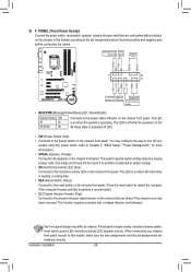
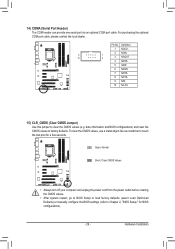
... a normal restart. • CI (Chassis Intrusion Header, Gray): Connects to the pin assignments below. When connecting your system using the power switch (refer to Chapter 2, "BIOS Setup," "Power Management," for more information). • SPEAK (Speaker, Orange): Connects to the power status indicator on the chassis that can detect if the chassis...
... a normal restart. • CI (Chassis Intrusion Header, Gray): Connects to the pin assignments below. When connecting your system using the power switch (refer to Chapter 2, "BIOS Setup," "Power Management," for more information). • SPEAK (Speaker, Orange): Connects to the power status indicator on the chassis that can detect if the chassis...
User Manual
Page 27
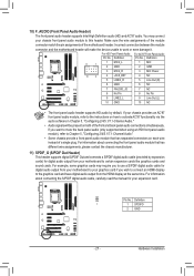
...for your graphics card if you want to work or even damage it. Definition Pin No. Definition XDP_CPU 1 1 SPDIFO XDP_PCH 2 GND (GA-IVB) - 27 - Make sure the wire assignments of the module connector match the pin assignments of a single plug. If your motherboard to...7 NC 8 No Pin 8 No Pin 9 LINE2_L 9 Line Out (L) 10 GND 10 NC F_PANEL (H61M-D2) DIP 1 23 1 DIP 1 23 1 DIP 1 23 1 BIOS Switcher (X58A-OC) DB_•P•ORTThe front panel audio header supports HD audio by expansion cardsP)CfIoerpodwigeritcaolnaneucdtoiro(SoAuTtAp)(uXt5f8rAo-mOC)your chassis provides an...
...for your graphics card if you want to work or even damage it. Definition Pin No. Definition XDP_CPU 1 1 SPDIFO XDP_PCH 2 GND (GA-IVB) - 27 - Make sure the wire assignments of the module connector match the pin assignments of a single plug. If your motherboard to...7 NC 8 No Pin 8 No Pin 9 LINE2_L 9 Line Out (L) 10 GND 10 NC F_PANEL (H61M-D2) DIP 1 23 1 DIP 1 23 1 DIP 1 23 1 BIOS Switcher (X58A-OC) DB_•P•ORTThe front panel audio header supports HD audio by expansion cardsP)CfIoerpodwigeritcaolnaneucdtoiro(SoAuTtAp)(uXt5f8rAo-mOC)your chassis provides an...
User Manual
Page 28
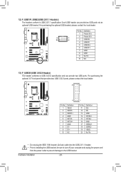
... two USB 3.0/2.0 ports, please contact the local dealer. 20 10 11 TPM w/housing Pin No. 1 2 3 4 5 6 7 8 9 10 Definition VBUS SSRX1SSRX1+ GND SSTX1SSTX1+ GND D1D1+ NC DB_PORT 1 1 BIOS Switche 1 1 Pin No. For purchasing the optional USB bracket, please contact the local dealer. Each USB header can provide two USB ports. 12) F_USB1/F_USB2...
... two USB 3.0/2.0 ports, please contact the local dealer. 20 10 11 TPM w/housing Pin No. 1 2 3 4 5 6 7 8 9 10 Definition VBUS SSRX1SSRX1+ GND SSTX1SSTX1+ GND D1D1+ NC DB_PORT 1 1 BIOS Switche 1 1 Pin No. For purchasing the optional USB bracket, please contact the local dealer. Each USB header can provide two USB ports. 12) F_USB1/F_USB2...
User Manual
Page 29
... clearing the CMOS values. •• After system restart, go to BIOS Setup to load factory defaults (select Load Optimized Defaults) or manually configure the BIOS settings (refer to touch the two pins for BIOS configurations). - 29 - To clear the CMOS values, use a metal... object like a screwdriver to Chapter 2, "BIOS Setup," for a few seconds. Hardware Installation For purchasing the...
... clearing the CMOS values. •• After system restart, go to BIOS Setup to load factory defaults (select Load Optimized Defaults) or manually configure the BIOS settings (refer to touch the two pins for BIOS configurations). - 29 - To clear the CMOS values, use a metal... object like a screwdriver to Chapter 2, "BIOS Setup," for a few seconds. Hardware Installation For purchasing the...
User Manual
Page 31
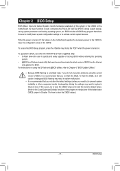
... if you need to) to activate certain system features. To flash the BIOS, do not encounter problems using the current version of BIOS, it with caution. To upgrade the BIOS, use either the GIGABYTE Q-Flash or @BIOS utility. •• Q-Flash allows the user to quickly and easily ...upgrade or back up BIOS without entering the operating system. •• @BIOS is a Windows-based utility ...
... if you need to) to activate certain system features. To flash the BIOS, do not encounter problems using the current version of BIOS, it with caution. To upgrade the BIOS, use either the GIGABYTE Q-Flash or @BIOS utility. •• Q-Flash allows the user to quickly and easily ...upgrade or back up BIOS without entering the operating system. •• @BIOS is a Windows-based utility ...
User Manual
Page 32
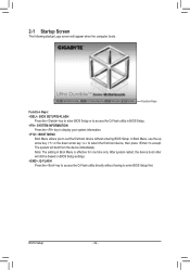
...device without having to access the Q-Flash utility in Boot Menu is effective for one time only. BIOS Setup - 32 - Function Keys Function Keys: : BIOS SETUP\Q-FLASH Press the key to enter BIOS Setup or to enter BIOS Setup first. After system restart, the device boot order will boot from the device immediately. The... system will still be based on BIOS Setup settings. : Q-FLASH Press the key to accept. In Boot Menu, use the up arrow key or the down arrow key to select the ...
...device without having to access the Q-Flash utility in Boot Menu is effective for one time only. BIOS Setup - 32 - Function Keys Function Keys: : BIOS SETUP\Q-FLASH Press the key to enter BIOS Setup or to enter BIOS Setup first. After system restart, the device boot order will boot from the device immediately. The... system will still be based on BIOS Setup settings. : Q-FLASH Press the key to accept. In Boot Menu, use the up arrow key or the down arrow key to select the ...
User Manual
Page 33
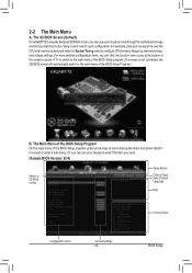
.... For example, pass your mouse to select the item you can use your mouse to move among the items and press to 3D BIOS screen Setup Menus Enter Q-Flash Select Default Language Help Function Keys Configuration Items Current Settings - 33 - For more detailed configuration items, ... move through the motherboard image and click to configure CPU/memory frequency, memory timings, and voltage settings. BIOS Setup The 3D BIOS Screen (Default) On GIGABYTE's uniquely designed 3D BIOS screen, you can use your mouse arrow over the CPU and memory sockets and enter the System Tuning...
.... For example, pass your mouse to select the item you can use your mouse to move among the items and press to 3D BIOS screen Setup Menus Enter Q-Flash Select Default Language Help Function Keys Configuration Items Current Settings - 33 - For more detailed configuration items, ... move through the motherboard image and click to configure CPU/memory frequency, memory timings, and voltage settings. BIOS Setup The 3D BIOS Screen (Default) On GIGABYTE's uniquely designed 3D BIOS screen, you can use your mouse arrow over the CPU and memory sockets and enter the System Tuning...


