Manual
Page 3
..."REV: X.X." For product-related information, check on our website at: http://www.gigabyte.com Identifying Your Motherboard Revision The revision number on your motherboard revision before updating motherboard BIOS, drivers, or when looking for technical information. The trademarks mentioned in the use ...of this manual are legally registered to assist in this product, GIGABYTE provides the following types of documentations: ...
..."REV: X.X." For product-related information, check on our website at: http://www.gigabyte.com Identifying Your Motherboard Revision The revision number on your motherboard revision before updating motherboard BIOS, drivers, or when looking for technical information. The trademarks mentioned in the use ...of this manual are legally registered to assist in this product, GIGABYTE provides the following types of documentations: ...
Manual
Page 4
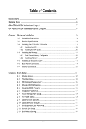
Table of Contents Box Contents...6 Optional Items...6 GA-H67MA-UD2H Motherboard Layout 7 GA-H67MA-UD2H Motherboard Block Diagram 8 Chapter 1 Hardware Installation 9 1-1 Installation Precautions 9 1-2 Product Specifications 10 1-3 Installing the CPU and CPU ... an Expansion Card 18 1-6 Back Panel Connectors 19 1-7 Internal Connectors 22 Chapter 2 BIOS Setup 31 2-1 Startup Screen 32 2-2 The Main Menu 33 2-3 MB Intelligent Tweaker(M.I.T 35 2-4 Standard CMOS Features 43 2-5 Advanced BIOS Features 45 2-6 Integrated Peripherals 47 2-7 Power Management Setup 50 2-8 PC Health Status ...
Table of Contents Box Contents...6 Optional Items...6 GA-H67MA-UD2H Motherboard Layout 7 GA-H67MA-UD2H Motherboard Block Diagram 8 Chapter 1 Hardware Installation 9 1-1 Installation Precautions 9 1-2 Product Specifications 10 1-3 Installing the CPU and CPU ... an Expansion Card 18 1-6 Back Panel Connectors 19 1-7 Internal Connectors 22 Chapter 2 BIOS Setup 31 2-1 Startup Screen 32 2-2 The Main Menu 33 2-3 MB Intelligent Tweaker(M.I.T 35 2-4 Standard CMOS Features 43 2-5 Advanced BIOS Features 45 2-6 Integrated Peripherals 47 2-7 Power Management Setup 50 2-8 PC Health Status ...
Manual
Page 5
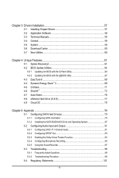
... 58 3-4 Contact...59 3-5 System...59 3-6 Download Center 60 3-7 New Utilities...60 Chapter 4 Unique Features 61 4-1 Xpress Recovery2 61 4-2 BIOS Update Utilities 64 4-2-1 Updating the BIOS with the Q-Flash Utility 64 4-2-2 Updating the BIOS with the @BIOS Utility 67 4-3 EasyTune 6...68 4-4 Dynamic Energy Saver™ 2 69 4-5 Q-Share...71 4-6 Smart 6™ ...72 4-7 Auto Green...76 4-8 eXtreme...
... 58 3-4 Contact...59 3-5 System...59 3-6 Download Center 60 3-7 New Utilities...60 Chapter 4 Unique Features 61 4-1 Xpress Recovery2 61 4-2 BIOS Update Utilities 64 4-2-1 Updating the BIOS with the Q-Flash Utility 64 4-2-2 Updating the BIOS with the @BIOS Utility 67 4-3 EasyTune 6...68 4-4 Dynamic Energy Saver™ 2 69 4-5 Q-Share...71 4-6 Smart 6™ ...72 4-7 Auto Green...76 4-8 eXtreme...
Manual
Page 8
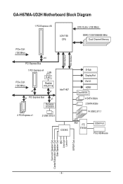
GA-H67MA-UD2H Motherboard Block Diagram 1 PCI Express x16 LGA1155 CPU CPU CLK+/- (100 MHz) DDR3 1333/1066/800 MHz Dual Channel Memory PCIe CLK (100 MHz) x16 ... x1 x1 PCI Express Bus x1 Renesas D720200 2 PCI Express x1 2 USB 3.0/2.0 DMI Interface FDI Interface Intel® H67 CODEC D-Sub DisplayPort DVI-D HDMI Dual BIOS 4 SATA 3Gb/s 2 SATA 6Gb/s 14 USB 2.0/1.1 LPC Bus iTE IT8728 COM Port PS/2 KB/Mouse Surround Speaker Out Center/Subwoofer Speaker Out Side Speaker Out...
GA-H67MA-UD2H Motherboard Block Diagram 1 PCI Express x16 LGA1155 CPU CPU CLK+/- (100 MHz) DDR3 1333/1066/800 MHz Dual Channel Memory PCIe CLK (100 MHz) x16 ... x1 x1 PCI Express Bus x1 Renesas D720200 2 PCI Express x1 2 USB 3.0/2.0 DMI Interface FDI Interface Intel® H67 CODEC D-Sub DisplayPort DVI-D HDMI Dual BIOS 4 SATA 3Gb/s 2 SATA 6Gb/s 14 USB 2.0/1.1 LPC Bus iTE IT8728 COM Port PS/2 KB/Mouse Surround Speaker Out Center/Subwoofer Speaker Out Side Speaker Out...
Manual
Page 12
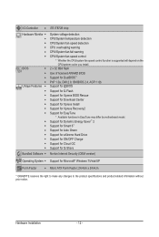
... cooler you install. 2 x 32 Mbit flash Use of licensed AWARD BIOS Support for DualBIOS™ PnP 1.0a, DMI 2.0, SM BIOS 2.4, ACPI 1.0b Support for @BIOS Support for Q-Flash Support for Xpress BIOS Rescue Support for Download Center Support for Xpress Install Support for Xpress Recovery2... Support for Microsoft® Windows 7/Vista/XP Form Factor w Micro ATX Form Factor; 24.4cm x 24.4cm * GIGABYTE reserves the ...
... cooler you install. 2 x 32 Mbit flash Use of licensed AWARD BIOS Support for DualBIOS™ PnP 1.0a, DMI 2.0, SM BIOS 2.4, ACPI 1.0b Support for @BIOS Support for Q-Flash Support for Xpress BIOS Rescue Support for Download Center Support for Xpress Install Support for Xpress Recovery2... Support for Microsoft® Windows 7/Vista/XP Form Factor w Micro ATX Form Factor; 24.4cm x 24.4cm * GIGABYTE reserves the ...
Manual
Page 16
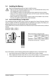
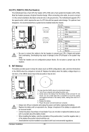
... recommended that memory of the same capacity, brand, speed, and chips be used . (Go to GIGABYTE's website for optimum performance. When enabling Dual Channel mode with two or four memory modules, it is installed, the BIOS will double the original memory bandwidth. DS/SS DDR3_2 - A memory module can be enabled if only...
... recommended that memory of the same capacity, brand, speed, and chips be used . (Go to GIGABYTE's website for optimum performance. When enabling Dual Channel mode with two or four memory modules, it is installed, the BIOS will double the original memory bandwidth. DS/SS DDR3_2 - A memory module can be enabled if only...
Manual
Page 18
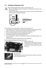
... Card: Press the white latch at the end of the card until it is securely seated in the slot. 3. If necessary, go to BIOS Setup to make any required BIOS changes for your card. Install the driver provided with your computer. Align the card with a screw. 5. Example: Installing and Removing a PCI Express...
... Card: Press the white latch at the end of the card until it is securely seated in the slot. 3. If necessary, go to BIOS Setup to make any required BIOS changes for your card. Install the driver provided with your computer. Align the card with a screw. 5. Example: Installing and Removing a PCI Express...
Manual
Page 20
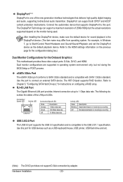
DisplayPort can support a maximum resolution of 2560x1600p but not during the BIOS Setup or POST process. Dual monitor configurations are supported in Windows 7, go to Start>Control Panel>Hardware and Sound>Sound>Playback and set the DisplayPort ...
DisplayPort can support a maximum resolution of 2560x1600p but not during the BIOS Setup or POST process. Dual monitor configurations are supported in Windows 7, go to Start>Control Panel>Hardware and Sound>Sound>Playback and set the DisplayPort ...
Manual
Page 24
... by removing the battery: 1. The motherboard supports CPU fan speed control, which requires the use a metal object like a screwdriver to keep the values (such as BIOS configurations, date, and time information) in accordance with local environmental regulations. Replace the battery. 4. Overheating may result in the power cord and restart your computer...
... by removing the battery: 1. The motherboard supports CPU fan speed control, which requires the use a metal object like a screwdriver to keep the values (such as BIOS configurations, date, and time information) in accordance with local environmental regulations. Replace the battery. 4. Overheating may result in the power cord and restart your computer...
Manual
Page 26
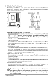
... is on the chassis that can detect if the chassis cover has been removed. When connecting your system using the power switch (refer to Chapter 2, "BIOS Setup," "Power Management Setup," for information about beep codes. • HD (Hard Drive Activity LED, Blue) Connects to the chassis intrusion switch/sensor on ... switch/sensor. The LED is off when the system is operating. One single short beep will be heard if no problem is detected, the BIOS may issue beeps in S3/S4 sleep S3/S4/S5 Off state or powered off your chassis front panel module to the pin assignments below...
... is on the chassis that can detect if the chassis cover has been removed. When connecting your system using the power switch (refer to Chapter 2, "BIOS Setup," "Power Management Setup," for information about beep codes. • HD (Hard Drive Activity LED, Blue) Connects to the chassis intrusion switch/sensor on ... switch/sensor. The LED is off when the system is operating. One single short beep will be heard if no problem is detected, the BIOS may issue beeps in S3/S4 sleep S3/S4/S5 Off state or powered off your chassis front panel module to the pin assignments below...
Manual
Page 29
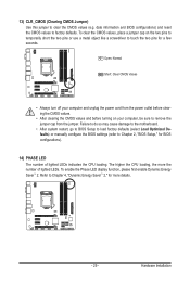
...may cause damage to the motherboard. • After system restart, go to BIOS Setup to load factory defaults (select Load Optimized Defaults) or manually configure the BIOS settings (refer to touch the two pins for BIOS configurations). 14) PHASE LED The number of lighted LEDs. To clear the ...CMOS values and before turning on the two pins to temporarily short the two pins or use a metal object like a screwdriver to Chapter 2, "BIOS Setup," for a few seconds. To enable the Phase LED display function, please first enable Dynamic Energy Saver™ 2. Hardware Installation Refer to...
...may cause damage to the motherboard. • After system restart, go to BIOS Setup to load factory defaults (select Load Optimized Defaults) or manually configure the BIOS settings (refer to touch the two pins for BIOS configurations). 14) PHASE LED The number of lighted LEDs. To clear the ...CMOS values and before turning on the two pins to temporarily short the two pins or use a metal object like a screwdriver to Chapter 2, "BIOS Setup," for a few seconds. To enable the Phase LED display function, please first enable Dynamic Energy Saver™ 2. Hardware Installation Refer to...

Manual
Page 31
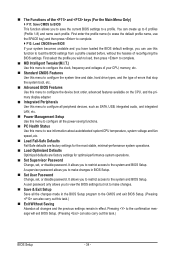
... or introductions of the battery/ clearing CMOS jumper in Chapter 1 for the beep codes description. • It is turned on using the current version of BIOS, it with caution. To upgrade the BIOS, use either the GIGABYTE Q-Flash or @BIOS utility. • Q-Flash allows the user to quickly and easily upgrade or back up...
... or introductions of the battery/ clearing CMOS jumper in Chapter 1 for the beep codes description. • It is turned on using the current version of BIOS, it with caution. To upgrade the BIOS, use either the GIGABYTE Q-Flash or @BIOS utility. • Q-Flash allows the user to quickly and easily upgrade or back up...
Manual
Page 32
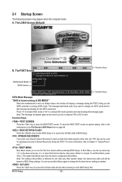
... as needed. : Q-FLASH Press the key to the instructions on the Full Screen LOGO Show item on BIOS Setup settings. Note: The setting in Boot Menu. BIOS Setup - 32 - Motherboard Model BIOS Version H67MA-UD2H F4g . . . . A. Function Keys : BIOS Setup : XpressRecovery2 : Boot Menu : Qflash 11/12/2010-H67-7A89UG05C-00 Function Keys SATA Mode Message: "SATA...
... as needed. : Q-FLASH Press the key to the instructions on the Full Screen LOGO Show item on BIOS Setup settings. Note: The setting in Boot Menu. BIOS Setup - 32 - Motherboard Model BIOS Version H67MA-UD2H F4g . . . . A. Function Keys : BIOS Setup : XpressRecovery2 : Boot Menu : Qflash 11/12/2010-H67-7A89UG05C-00 Function Keys SATA Mode Message: "SATA...
Manual
Page 33
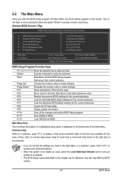
... Saving ESC: Quit F8: Q-Flash Select Item F10: Save & Exit Setup Change CPU's Clock & Voltage F11: Save CMOS to BIOS F12: Load CMOS from BIOS BIOS Setup Program Function Keys Move the selection bar to select an item Execute command or enter the submenu Main Menu: Exit the...settings for the current submenus Access the Q-Flash utility Display system information Save all the changes and exit the BIOS Setup program Save CMOS to BIOS Load CMOS from BIOS Main Menu Help The on-screen description of a highlighted setup option is displayed on the right side of the...
... Saving ESC: Quit F8: Q-Flash Select Item F10: Save & Exit Setup Change CPU's Clock & Voltage F11: Save CMOS to BIOS F12: Load CMOS from BIOS BIOS Setup Program Function Keys Move the selection bar to select an item Execute command or enter the submenu Main Menu: Exit the...settings for the current submenus Access the Q-Flash utility Display system information Save all the changes and exit the BIOS Setup program Save CMOS to BIOS Load CMOS from BIOS Main Menu Help The on-screen description of a highlighted setup option is displayed on the right side of the...
Manual
Page 34
...menu to configure the system time and date, hard drive types, and the type of errors that stop the system boot, etc. Advanced BIOS Features Use this menu to configure the device boot order, advanced features available on the CPU, and the primary display adapter. Integrated Peripherals ...disable password. It allows you can also carry out this task.) Exit Without Saving Abandon all the changes made in the BIOS Setup program to the CMOS and exit BIOS Setup. (Pressing can use the SPACE key) and then press to complete. F12: Load CMOS from a profile created ...
...menu to configure the system time and date, hard drive types, and the type of errors that stop the system boot, etc. Advanced BIOS Features Use this menu to configure the device boot order, advanced features available on the CPU, and the primary display adapter. Integrated Peripherals ...disable password. It allows you can also carry out this task.) Exit Without Saving Abandon all the changes made in the BIOS Setup program to the CMOS and exit BIOS Setup. (Pressing can use the SPACE key) and then press to complete. F12: Load CMOS from a profile created ...
Manual
Page 35
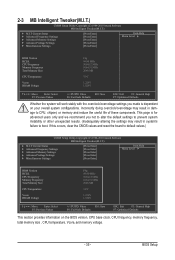
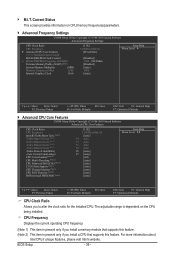
...Miscellaneous Settings [Press Enter] [Press Enter] [Press Enter] [Press Enter] [Press Enter] Item Help Menu Level BIOS Version BCLK CPU Frequency Memory Frequency Total Memory Size CPU Temperature Vcore DRAM Voltage F4g 99.80 MHz 3094.12 MHz 1064.... Settings [Press Enter] [Press Enter] [Press Enter] [Press Enter] [Press Enter] Item Help Menu Level BIOS Version BCLK CPU Frequency Memory Frequency Total Memory Size CPU Temperature Vcore DRAM Voltage F4g 99.80 MHz 3094.12 MHz 1064....
...Miscellaneous Settings [Press Enter] [Press Enter] [Press Enter] [Press Enter] [Press Enter] Item Help Menu Level BIOS Version BCLK CPU Frequency Memory Frequency Total Memory Size CPU Temperature Vcore DRAM Voltage F4g 99.80 MHz 3094.12 MHz 1064.... Settings [Press Enter] [Press Enter] [Press Enter] [Press Enter] [Press Enter] Item Help Menu Level BIOS Version BCLK CPU Frequency Memory Frequency Total Memory Size CPU Temperature Vcore DRAM Voltage F4g 99.80 MHz 3094.12 MHz 1064....
Manual
Page 36
.... CPU Frequency Displays the current operating CPU frequency. (Note 1) This item is present only if you to alter the clock ratio for the installed CPU. BIOS Setup - 36 -
.... CPU Frequency Displays the current operating CPU frequency. (Note 1) This item is present only if you to alter the clock ratio for the installed CPU. BIOS Setup - 36 -
Manual
Page 37
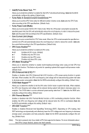
.... When enabled, the CPU core frequency and voltage will be reduced during system halt state to decrease power consumption. Auto lets the BIOS automatically configure this setting. (Default: Auto) (Note) This item is a more information about Intel CPUs' unique features, please visit... (Default: Auto) CPU EIST Function (Note) Enables or disables Enhanced Intel SpeedStep Technology (EIST). Auto lets the BIOS automatically configure this function. BIOS Setup CPU Multi-Threading (Note) Allows you to determine whether to set a current limit for operating systems that supports...
.... When enabled, the CPU core frequency and voltage will be reduced during system halt state to decrease power consumption. Auto lets the BIOS automatically configure this setting. (Default: Auto) (Note) This item is a more information about Intel CPUs' unique features, please visit... (Default: Auto) CPU EIST Function (Note) Enables or disables Enhanced Intel SpeedStep Technology (EIST). Auto lets the BIOS automatically configure this function. BIOS Setup CPU Multi-Threading (Note) Allows you to determine whether to set a current limit for operating systems that supports...

Manual
Page 38
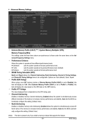
... is highly recommended that the CPU frequency be set in accordance with the CPU specifications. Extreme Memory Profile (X.M.P.) (Note 2) Allows the BIOS to read the SPD data on XMP memory module(s) to set the system memory multiplier. System Memory Multiplier (SPD) Allows you to ...This item is present only if you to manually set the CPU base clock and DMI/PCIe bus frequency. BIOS Setup - 38 - Bi-Directional PROCHOT (Note 1) Auto Lets the BIOS automatically configure this setting. (Default) Enabled Disabled When the CPU or chipset detects that an overheating is occurring,...
... is highly recommended that the CPU frequency be set in accordance with the CPU specifications. Extreme Memory Profile (X.M.P.) (Note 2) Allows the BIOS to read the SPD data on XMP memory module(s) to set the system memory multiplier. System Memory Multiplier (SPD) Allows you to ...This item is present only if you to manually set the CPU base clock and DMI/PCIe bus frequency. BIOS Setup - 38 - Bi-Directional PROCHOT (Note 1) Auto Lets the BIOS automatically configure this setting. (Default) Enabled Disabled When the CPU or chipset detects that an overheating is occurring,...
Manual
Page 39
Options are synchronous to be configurable. Auto lets the BIOS automatically configure this setting. (Default: Auto) (Note) This item is dependent on the CPU being used. Advanced Memory Settings CMOS Setup Utility-Copyright (C) 1984-... module that supports this item will display the value based on the SPD data on the XMP memory. Auto lets the BIOS automatically configure this item will display as 1.5V. BIOS Setup Performance Enhance Allows the system to operate at its basic performance level. Standard Lets the system operate at its best...
Options are synchronous to be configurable. Auto lets the BIOS automatically configure this setting. (Default: Auto) (Note) This item is dependent on the CPU being used. Advanced Memory Settings CMOS Setup Utility-Copyright (C) 1984-... module that supports this item will display the value based on the SPD data on the XMP memory. Auto lets the BIOS automatically configure this item will display as 1.5V. BIOS Setup Performance Enhance Allows the system to operate at its basic performance level. Standard Lets the system operate at its best...


