Manual
Page 3
... Revision The revision number on your motherboard revision before updating motherboard BIOS, drivers, or when looking for technical information. Check your motherboard looks like this manual may be made by GIGABYTE without GIGABYTE's prior written permission. The trademarks mentioned in this manual are ... features in any means without prior notice. Copyright © 2010 GIGA-BYTE TECHNOLOGY CO., LTD. All rights reserved. No part of GIGABYTE. Disclaimer Information in the use of this manual may be reproduced, copied, translated, transmitted, or published in this : "REV: X.X."...
... Revision The revision number on your motherboard revision before updating motherboard BIOS, drivers, or when looking for technical information. Check your motherboard looks like this manual may be made by GIGABYTE without GIGABYTE's prior written permission. The trademarks mentioned in this manual are ... features in any means without prior notice. Copyright © 2010 GIGA-BYTE TECHNOLOGY CO., LTD. All rights reserved. No part of GIGABYTE. Disclaimer Information in the use of this manual may be reproduced, copied, translated, transmitted, or published in this : "REV: X.X."...

Manual
Page 4
Table of Contents Box Contents...6 Optional Items...6 GA-H67A-UD3H Motherboard Layout 7 GA-H67A-UD3H Motherboard Block Diagram 8 Chapter 1 Hardware Installation 9 1-1 Installation Precautions 9 1-2 Product Specifications 10 1-3 Installing the CPU and CPU ... an Expansion Card 18 1-6 Back Panel Connectors 19 1-7 Internal Connectors 22 Chapter 2 BIOS Setup 31 2-1 Startup Screen 32 2-2 The Main Menu 33 2-3 MB Intelligent Tweaker(M.I.T 35 2-4 Standard CMOS Features 43 2-5 Advanced BIOS Features 45 2-6 Integrated Peripherals 47 2-7 Power Management Setup 50 2-8 PC Health Status ...
Table of Contents Box Contents...6 Optional Items...6 GA-H67A-UD3H Motherboard Layout 7 GA-H67A-UD3H Motherboard Block Diagram 8 Chapter 1 Hardware Installation 9 1-1 Installation Precautions 9 1-2 Product Specifications 10 1-3 Installing the CPU and CPU ... an Expansion Card 18 1-6 Back Panel Connectors 19 1-7 Internal Connectors 22 Chapter 2 BIOS Setup 31 2-1 Startup Screen 32 2-2 The Main Menu 33 2-3 MB Intelligent Tweaker(M.I.T 35 2-4 Standard CMOS Features 43 2-5 Advanced BIOS Features 45 2-6 Integrated Peripherals 47 2-7 Power Management Setup 50 2-8 PC Health Status ...

Manual
Page 5
... 58 3-4 Contact...59 3-5 System...59 3-6 Download Center 60 3-7 New Utilities...60 Chapter 4 Unique Features 61 4-1 Xpress Recovery2 61 4-2 BIOS Update Utilities 64 4-2-1 Updating the BIOS with the Q-Flash Utility 64 4-2-2 Updating the BIOS with the @BIOS Utility 67 4-3 EasyTune 6...68 4-4 Dynamic Energy Saver™ 2 69 4-5 Q-Share...71 4-6 Smart 6™ ...72 4-7 Auto Green...76 4-8 eXtreme...
... 58 3-4 Contact...59 3-5 System...59 3-6 Download Center 60 3-7 New Utilities...60 Chapter 4 Unique Features 61 4-1 Xpress Recovery2 61 4-2 BIOS Update Utilities 64 4-2-1 Updating the BIOS with the Q-Flash Utility 64 4-2-2 Updating the BIOS with the @BIOS Utility 67 4-3 EasyTune 6...68 4-4 Dynamic Energy Saver™ 2 69 4-5 Q-Share...71 4-6 Smart 6™ ...72 4-7 Auto Green...76 4-8 eXtreme...

Manual
Page 8
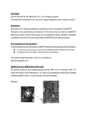
GA-H67A-UD3H Motherboard Block Diagram 1 PCI Express x16 PCIe CLK (100 MHz) LGA1155 CPU CPU CLK+/- (100 MHz) DDR3 1333/1066/800 MHz Dual Channel Memory PCI ... 3.0/2.0 x4 Switch PCI Express Bus x1 Renesas D720200 x1 x1 x1 x1 Realtek RTL8111E iTE IT8892 Bridge Intel® H67 DisplayPort HDMI DVI-D D-Sub Dual BIOS 2 SATA 6Gb/s 4 SATA 3Gb/s 1 PCI Express x1 RJ45 LAN PCI Bus TSB43AB23 14 USB 2.0/1.1 CODEC LPC Bus iTE IT8728 COM PS/2 KB/Mouse 3 IEEE 1394a...
GA-H67A-UD3H Motherboard Block Diagram 1 PCI Express x16 PCIe CLK (100 MHz) LGA1155 CPU CPU CLK+/- (100 MHz) DDR3 1333/1066/800 MHz Dual Channel Memory PCI ... 3.0/2.0 x4 Switch PCI Express Bus x1 Renesas D720200 x1 x1 x1 x1 Realtek RTL8111E iTE IT8892 Bridge Intel® H67 DisplayPort HDMI DVI-D D-Sub Dual BIOS 2 SATA 6Gb/s 4 SATA 3Gb/s 1 PCI Express x1 RJ45 LAN PCI Bus TSB43AB23 14 USB 2.0/1.1 CODEC LPC Bus iTE IT8728 COM PS/2 KB/Mouse 3 IEEE 1394a...

Manual
Page 12
... cooler you install. 2 x 32 Mbit flash Use of licensed AWARD BIOS Support for DualBIOS™ PnP 1.0a, DMI 2.0, SM BIOS 2.4, ACPI 1.0b Support for @BIOS Support for Q-Flash Support for Xpress BIOS Rescue Support for Download Center Support for Xpress Install Support for Xpress Recovery2... Support for Microsoft® Windows® 7/Vista/XP Form Factor w ATX Form Factor; 30.5cm x 24.4cm * GIGABYTE reserves the ...
... cooler you install. 2 x 32 Mbit flash Use of licensed AWARD BIOS Support for DualBIOS™ PnP 1.0a, DMI 2.0, SM BIOS 2.4, ACPI 1.0b Support for @BIOS Support for Q-Flash Support for Xpress BIOS Rescue Support for Download Center Support for Xpress Install Support for Xpress Recovery2... Support for Microsoft® Windows® 7/Vista/XP Form Factor w ATX Form Factor; 30.5cm x 24.4cm * GIGABYTE reserves the ...

Manual
Page 16
...Channel 1: DDR3_3, DDR3_4 Dual Channel Memory Configurations Table DDR3_1 DDR3_2 DDR3_3 DDR3_4 Two Modules DS/SS - - After the memory is installed, the BIOS will double the original memory bandwidth. When enabling Dual Channel mode with two or four memory modules, it is recommended that memory of the ...speeds and memory modules.) • Always turn off the computer and unplug the power cord from the power outlet before installing the memory to GIGABYTE's website for optimum performance. It is recommended that memory of the same capacity, brand, speed, and chips be used . (Go to ...
...Channel 1: DDR3_3, DDR3_4 Dual Channel Memory Configurations Table DDR3_1 DDR3_2 DDR3_3 DDR3_4 Two Modules DS/SS - - After the memory is installed, the BIOS will double the original memory bandwidth. When enabling Dual Channel mode with two or four memory modules, it is recommended that memory of the ...speeds and memory modules.) • Always turn off the computer and unplug the power cord from the power outlet before installing the memory to GIGABYTE's website for optimum performance. It is recommended that memory of the same capacity, brand, speed, and chips be used . (Go to ...

Manual
Page 18
... then pull the card straight up from the slot. Make sure the metal contacts on your expansion card(s). 7. If necessary, go to BIOS Setup to make any required BIOS changes for your computer. 1-5 Installing an Expansion Card Read the following guidelines before installing an expansion card to prevent hardware damage. Carefully read...
... then pull the card straight up from the slot. Make sure the metal contacts on your expansion card(s). 7. If necessary, go to BIOS Setup to make any required BIOS changes for your computer. 1-5 Installing an Expansion Card Read the following guidelines before installing an expansion card to prevent hardware damage. Carefully read...

Manual
Page 20
... name may differ from operating system. Side Speaker Out Jack (Gray) Use this port. DisplayPort can support a maximum resolution of 2560x1600p but not during the BIOS Setup or POST process. The DisplayPort Technology can support both DPCP and HDCP content protection mechanisms. Connect the audio/video device that delivers high quality...
... name may differ from operating system. Side Speaker Out Jack (Gray) Use this port. DisplayPort can support a maximum resolution of 2560x1600p but not during the BIOS Setup or POST process. The DisplayPort Technology can support both DPCP and HDCP content protection mechanisms. Connect the audio/video device that delivers high quality...

Manual
Page 26
Danger of explosion if the battery is turned off. 8) BAT (Battery) The battery provides power to keep the values (such as BIOS configurations, date, and time information) in the CMOS when the computer is replaced with an equivalent one minute. (Or use a metal object like graphics cards ...
Danger of explosion if the battery is turned off. 8) BAT (Battery) The battery provides power to keep the values (such as BIOS configurations, date, and time information) in the CMOS when the computer is replaced with an equivalent one minute. (Or use a metal object like graphics cards ...

Manual
Page 27
... front panel. This function requires a chassis with a chassis intrusion switch/sensor. When connecting your system using the power switch (refer to Chapter 2, "BIOS Setup," "Power Management Setup," for information about beep codes. • HD (Hard Drive Activity LED, Blue) Connects to the pin assignments below. ... (Power Switch, Red): Connects to the reset switch on the chassis front panel. The LED is on when the hard drive is detected, the BIOS may differ by issuing a beep code. RES+ RES- If a problem is reading or writing data. • RES (Reset Switch, Green): Connects...
... front panel. This function requires a chassis with a chassis intrusion switch/sensor. When connecting your system using the power switch (refer to Chapter 2, "BIOS Setup," "Power Management Setup," for information about beep codes. • HD (Hard Drive Activity LED, Blue) Connects to the pin assignments below. ... (Power Switch, Red): Connects to the reset switch on the chassis front panel. The LED is on when the hard drive is detected, the BIOS may differ by issuing a beep code. RES+ RES- If a problem is reading or writing data. • RES (Reset Switch, Green): Connects...

Manual
Page 30
...30 - Failure to do so may cause damage to the motherboard. • After system restart, go to BIOS Setup to load factory defaults (select Load Optimized Defaults) or manually configure the BIOS settings (refer to touch the two pins for more the number of lighted LEDs indicates the CPU loading. ...CMOS values and before turning on the two pins to temporarily short the two pins or use a metal object like a screwdriver to Chapter 2, "BIOS Setup," for BIOS configurations). 16) PHASE LED The number of lighted LEDs. To clear the CMOS values, place a jumper cap on your computer, be sure ...
...30 - Failure to do so may cause damage to the motherboard. • After system restart, go to BIOS Setup to load factory defaults (select Load Optimized Defaults) or manually configure the BIOS settings (refer to touch the two pins for more the number of lighted LEDs indicates the CPU loading. ...CMOS values and before turning on the two pins to temporarily short the two pins or use a metal object like a screwdriver to Chapter 2, "BIOS Setup," for BIOS configurations). 16) PHASE LED The number of lighted LEDs. To clear the CMOS values, place a jumper cap on your computer, be sure ...

Manual
Page 31
... the configuration values in the main menu of the BIOS Setup program. BIOS includes a BIOS Setup program that searches and downloads the latest version of BIOS from the Internet and updates the BIOS. To upgrade the BIOS, use either the GIGABYTE Q-Flash or @BIOS utility. • Q-Flash allows the user to ... or introductions of the battery/ clearing CMOS jumper in system's failure to quickly and easily upgrade or back up BIOS without entering the operating system. • @BIOS is recommended that you not alter the default settings (unless you can press + in the CMOS. When the...
... the configuration values in the main menu of the BIOS Setup program. BIOS includes a BIOS Setup program that searches and downloads the latest version of BIOS from the Internet and updates the BIOS. To upgrade the BIOS, use either the GIGABYTE Q-Flash or @BIOS utility. • Q-Flash allows the user to ... or introductions of the battery/ clearing CMOS jumper in system's failure to quickly and easily upgrade or back up BIOS without entering the operating system. • @BIOS is recommended that you not alter the default settings (unless you can press + in the CMOS. When the...

Manual
Page 32
... ever entered Xpress Recovery2 to back up arrow key or the down arrow key to select the first boot device, then press to enter BIOS Setup first. A. H67A-UD3H F5e . . . . : BIOS Setup : XpressRecovery2 : Boot Menu : Qflash 11/16/2010-H67-7A89UG06C-00 Function Keys SATA Mode Message: "SATA is set the first boot device...
... ever entered Xpress Recovery2 to back up arrow key or the down arrow key to select the first boot device, then press to enter BIOS Setup first. A. H67A-UD3H F5e . . . . : BIOS Setup : XpressRecovery2 : Boot Menu : Qflash 11/16/2010-H67-7A89UG06C-00 Function Keys SATA Mode Message: "SATA is set the first boot device...

Manual
Page 33
...Without Saving ESC: Quit F8: Q-Flash Select Item F10: Save & Exit Setup Change CPU's Clock & Voltage F11: Save CMOS to BIOS F12: Load CMOS from BIOS BIOS Setup Program Function Keys Move the selection bar to select an item Execute command or enter the submenu Main Menu: Exit the...available for the current submenus Access the Q-Flash utility Display system information Save all the changes and exit the BIOS Setup program Save CMOS to BIOS Load CMOS from BIOS Main Menu Help The on-screen description of a highlighted setup option is not stable as usual, select ...
...Without Saving ESC: Quit F8: Q-Flash Select Item F10: Save & Exit Setup Change CPU's Clock & Voltage F11: Save CMOS to BIOS F12: Load CMOS from BIOS BIOS Setup Program Function Keys Move the selection bar to select an item Execute command or enter the submenu Main Menu: Exit the...available for the current submenus Access the Q-Flash utility Display system information Save all the changes and exit the BIOS Setup program Save CMOS to BIOS Load CMOS from BIOS Main Menu Help The on-screen description of a highlighted setup option is not stable as usual, select ...

Manual
Page 34
...to configure the system time and date, hard drive types, and the type of errors that stop the system boot, etc. Advanced BIOS Features Use this menu to configure the device boot order, advanced features available on the CPU, and the primary display adapter. Integrated ... USB, integrated audio, and integrated LAN, etc. Power Management Setup Use this menu to configure all changes and the previous settings remain in BIOS Setup. Set User Password Change, set , or disable password. You can also carry out this task.) Exit Without Saving Abandon all...
...to configure the system time and date, hard drive types, and the type of errors that stop the system boot, etc. Advanced BIOS Features Use this menu to configure the device boot order, advanced features available on the CPU, and the primary display adapter. Integrated ... USB, integrated audio, and integrated LAN, etc. Power Management Setup Use this menu to configure all changes and the previous settings remain in BIOS Setup. Set User Password Change, set , or disable password. You can also carry out this task.) Exit Without Saving Abandon all...

Manual
Page 35
...Miscellaneous Settings [Press Enter] [Press Enter] [Press Enter] [Press Enter] [Press Enter] Item Help Menu Level BIOS Version BCLK CPU Frequency Memory Frequency Total Memory Size CPU Temperature Vcore DRAM Voltage F5e 99.80 MHz 3094.12 MHz 1332.... Settings [Press Enter] [Press Enter] [Press Enter] [Press Enter] [Press Enter] Item Help Menu Level BIOS Version BCLK CPU Frequency Memory Frequency Total Memory Size CPU Temperature Vcore DRAM Voltage F5e 99.80 MHz 3094.12 MHz 1332....
...Miscellaneous Settings [Press Enter] [Press Enter] [Press Enter] [Press Enter] [Press Enter] Item Help Menu Level BIOS Version BCLK CPU Frequency Memory Frequency Total Memory Size CPU Temperature Vcore DRAM Voltage F5e 99.80 MHz 3094.12 MHz 1332.... Settings [Press Enter] [Press Enter] [Press Enter] [Press Enter] [Press Enter] Item Help Menu Level BIOS Version BCLK CPU Frequency Memory Frequency Total Memory Size CPU Temperature Vcore DRAM Voltage F5e 99.80 MHz 3094.12 MHz 1332....

Manual
Page 36
CPU Frequency Displays the current operating CPU frequency. (Note 1) This item is present only when you install a memory module that supports this feature. BIOS Setup - 36 - M.I.T. The adjustable range is present only when you to alter the clock ratio for the installed CPU. Current Status This screen provides ...
CPU Frequency Displays the current operating CPU frequency. (Note 1) This item is present only when you install a memory module that supports this feature. BIOS Setup - 36 - M.I.T. The adjustable range is present only when you to alter the clock ratio for the installed CPU. Current Status This screen provides ...

Manual
Page 37
... Enables or disables Intel CPU Enhanced Halt (C1E) function, a CPU power-saving function in system halt state. Auto lets the BIOS automatically configure this setting. (Default: Auto) Turbo Ratio (1-Core)/(2-Core)/(3-Core)/(4-Core) (Note) Allows you to determine whether to ...decrease power consumption. Auto lets the BIOS automatically configure this setting. (Default: Auto) (Note) This item is a more information about Intel CPUs' unique features, please visit Intel...
... Enables or disables Intel CPU Enhanced Halt (C1E) function, a CPU power-saving function in system halt state. Auto lets the BIOS automatically configure this setting. (Default: Auto) Turbo Ratio (1-Core)/(2-Core)/(3-Core)/(4-Core) (Note) Allows you to determine whether to ...decrease power consumption. Auto lets the BIOS automatically configure this setting. (Default: Auto) (Note) This item is a more information about Intel CPUs' unique features, please visit Intel...

Manual
Page 38
...memory frequency value is occurring to detect whether an overheating is the normal operating frequency of CPU base clock and DMI/PCIe bus frequency. BIOS Setup - 38 - Disabled Only allows the CPU to emit PROCHOT signals. >>>>> Standard Clock Control BCLK/DMI/PEG Clock Control Enables or... 2000 MHz. The adjustable range is from 800 MHz to set the onboard graphics clock. Bi-Directional PROCHOT (Note 1) Auto Lets the BIOS automatically configure this setting. (Default) Enabled When the CPU or chipset detects that an overheating is present only when you install a CPU that...
...memory frequency value is occurring to detect whether an overheating is the normal operating frequency of CPU base clock and DMI/PCIe bus frequency. BIOS Setup - 38 - Disabled Only allows the CPU to emit PROCHOT signals. >>>>> Standard Clock Control BCLK/DMI/PEG Clock Control Enables or... 2000 MHz. The adjustable range is from 800 MHz to set the onboard graphics clock. Bi-Directional PROCHOT (Note 1) Auto Lets the BIOS automatically configure this setting. (Default) Enabled When the CPU or chipset detects that an overheating is present only when you install a CPU that...

Manual
Page 39
...XMP memory module or Extreme Memory Profile (X.M.P.) is set to those under the three items above are : Auto (default), Quick, Expert. BIOS Setup Performance Enhance Allows the system to increase memory performance and stability. Options are synchronous to Disabled, this setting. (Default: Auto) ... memory performance and stability. When Extreme Memory Profile (X.M.P.) is set to Profile1 or Profile2, this feature. - 39 - Auto lets the BIOS automatically configure this setting. (Default: Auto) (Note) This item is dependent on the CPU being used. Profile VTT Voltage The value ...
...XMP memory module or Extreme Memory Profile (X.M.P.) is set to those under the three items above are : Auto (default), Quick, Expert. BIOS Setup Performance Enhance Allows the system to increase memory performance and stability. Options are synchronous to Disabled, this setting. (Default: Auto) ... memory performance and stability. When Extreme Memory Profile (X.M.P.) is set to Profile1 or Profile2, this feature. - 39 - Auto lets the BIOS automatically configure this setting. (Default: Auto) (Note) This item is dependent on the CPU being used. Profile VTT Voltage The value ...


