
Manual
Page 4
Motherboard GA-H61TN Feb. 08, 2013 Motherboard GA-H61TN Feb. 08, 2013
Motherboard GA-H61TN Feb. 08, 2013 Motherboard GA-H61TN Feb. 08, 2013

Manual
Page 6
Table of Contents Box Contents...7 GA-H77TN/GA-B75TN/GA-H61TN Motherboard Layout 8 Chapter 1 Hardware Installation 9 1-1 Installation Precautions 9 1-2 Product Specifications 10 1-3 Installing the CPU and CPU Cooler 13 1-4 Installing the Memory/Expansion Card 13 1-5 Back Panel Connectors ...
Table of Contents Box Contents...7 GA-H77TN/GA-B75TN/GA-H61TN Motherboard Layout 8 Chapter 1 Hardware Installation 9 1-1 Installation Precautions 9 1-2 Product Specifications 10 1-3 Installing the CPU and CPU Cooler 13 1-4 Installing the Memory/Expansion Card 13 1-5 Back Panel Connectors ...

Manual
Page 7
I/O Shield ;; Screws kit for expansion cards • The box contents above are for reference only and the actual items shall depend on the product package you obtain. - 7 - Motherboard driver disk ;; User's Manual ;; One SATA power cable ;; GA-H77TN or GA-B75TN or GA-H61TN motherboard ;; Box Contents ;;
I/O Shield ;; Screws kit for expansion cards • The box contents above are for reference only and the actual items shall depend on the product package you obtain. - 7 - Motherboard driver disk ;; User's Manual ;; One SATA power cable ;; GA-H77TN or GA-B75TN or GA-H61TN motherboard ;; Box Contents ;;

Manual
Page 8
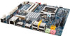
OO Only for GA-H77TN. GA-H77TN/GA-B75TN/GA-H61TN Motherboard Layout F_USB2_3 F_USB2_2 Socket 1155 PCIEX4 BIOS EXT_CON SPKR MIC_IN FP_AUDIO DMIC_CON CODEC LINE_OUT iTE Super I/O USBX_2 USBX_1 BATTERY Intel® H77j/ B75k/H61l HDMI FUSB2_1 FPD_PWR LCD_VCC WF_LED BL_SW SO_DIMM1 SO_DIMM2 MPCIE1X Realtek GbE LAN DP LAN SATA_PWR SYS_FAN SATA0 SATA1 SATA3jk SATA2 CLR_CMOS FUSB2_5 ATX_19V DC_IN LVDS SYS_PANEL CPU_FAN DISPLAY_BRT MON_SW MM Only for GA-H61TN. - 8 - NN Only for GA-B75TN.
OO Only for GA-H77TN. GA-H77TN/GA-B75TN/GA-H61TN Motherboard Layout F_USB2_3 F_USB2_2 Socket 1155 PCIEX4 BIOS EXT_CON SPKR MIC_IN FP_AUDIO DMIC_CON CODEC LINE_OUT iTE Super I/O USBX_2 USBX_1 BATTERY Intel® H77j/ B75k/H61l HDMI FUSB2_1 FPD_PWR LCD_VCC WF_LED BL_SW SO_DIMM1 SO_DIMM2 MPCIE1X Realtek GbE LAN DP LAN SATA_PWR SYS_FAN SATA0 SATA1 SATA3jk SATA2 CLR_CMOS FUSB2_5 ATX_19V DC_IN LVDS SYS_PANEL CPU_FAN DISPLAY_BRT MON_SW MM Only for GA-H61TN. - 8 - NN Only for GA-B75TN.
Manual
Page 9
...warranty validation. •• Always remove the AC power by your hardware components are connected. •• To prevent damage to the motherboard, do not have an ESD wrist strap, keep your hands dry and first touch a metal object to eliminate static electricity. ••...; Prior to installing the motherboard, please have a problem related to wear an electrostatic discharge (ESD) wrist strap when handling electronic components such as a result of your dealer...
...warranty validation. •• Always remove the AC power by your hardware components are connected. •• To prevent damage to the motherboard, do not have an ESD wrist strap, keep your hands dry and first touch a metal object to eliminate static electricity. ••...; Prior to installing the motherboard, please have a problem related to wear an electrostatic discharge (ESD) wrist strap when handling electronic components such as a result of your dealer...
Manual
Page 13
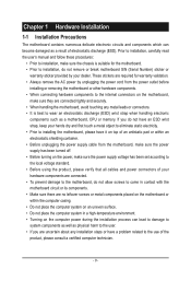
...the standard requirements for the latest supported memory speeds and memory modules.) •• Make sure the motherboard supports the expansion card. A memory module can be used. (Go to GIGABYTE's website for the peripherals. It is not installed, otherwise overheating and damage of the CPU. 1-3 ...inserted if oriented incorrectly. (Or you begin to install the CPU/CPU cooler: •• Make sure that the motherboard supports the CPU. (Go to GIGABYTE's website for the latest CPU support list.) •• Always turn off the computer and unplug the power cord from...
...the standard requirements for the latest supported memory speeds and memory modules.) •• Make sure the motherboard supports the expansion card. A memory module can be used. (Go to GIGABYTE's website for the peripherals. It is not installed, otherwise overheating and damage of the CPU. 1-3 ...inserted if oriented incorrectly. (Or you begin to install the CPU/CPU cooler: •• Make sure that the motherboard supports the CPU. (Go to GIGABYTE's website for the latest CPU support list.) •• Always turn off the computer and unplug the power cord from...

Manual
Page 15
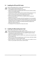
...printer, USB flash drive and etc. Use this port for GA-H61TN. - 15 - USB 2.0 Ports l The USB port supports the USB 2.0 specification. MIC In (Pink) The default MIC In jack. MM Only for GA-B75TN. Do not rock it straight out from the motherboard. • When removing the cable, pull it side to... side to prevent an electrical short inside the cable connector. Line Out (Front Speaker Out/Green) The default Line Out (Front Speaker Out) jack. NN Only for GA-H77TN. USB 3.0 Ports jk The ...
...printer, USB flash drive and etc. Use this port for GA-H61TN. - 15 - USB 2.0 Ports l The USB port supports the USB 2.0 specification. MIC In (Pink) The default MIC In jack. MM Only for GA-B75TN. Do not rock it straight out from the motherboard. • When removing the cable, pull it side to... side to prevent an electrical short inside the cable connector. Line Out (Front Speaker Out/Green) The default Line Out (Front Speaker Out) jack. NN Only for GA-H77TN. USB 3.0 Ports jk The ...

Manual
Page 16
..., make sure your devices are compliant with the connectors you wish to connect. • Before installing the devices, be sure to the connector on the motherboard. - 16 -
..., make sure your devices are compliant with the connectors you wish to connect. • Before installing the devices, be sure to the connector on the motherboard. - 16 -

Manual
Page 20
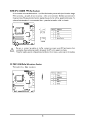
... 2.0/1.1 Headers) The headers conform to this header. Each header supports a single device. Incorrect connection between the module connector and the motherboard header will be present on each wire instead of the motherboard header. Definition 1 F_MIC_L 10 9 2 GND 3 F_MIC_R 2 1 4 GPIO_DET 5 F_LINE_R 6 F_MIC_JD 7 GND 8 No Pin 9 F_LINE_L 10 F_LINE_JD • The front panel audio...
... 2.0/1.1 Headers) The headers conform to this header. Each header supports a single device. Incorrect connection between the module connector and the motherboard header will be present on each wire instead of the motherboard header. Definition 1 F_MIC_L 10 9 2 GND 3 F_MIC_R 2 1 4 GPIO_DET 5 F_LINE_R 6 F_MIC_JD 7 GND 8 No Pin 9 F_LINE_L 10 F_LINE_JD • The front panel audio...
Manual
Page 22
... is the ground wire). The speed control function requires the use of a fan with fan speed control design. Do not place a jumper cap on this motherboard are not configuration jumper blocks. When connecting a fan cable, be sure to connect it is recommended that a system fan be installed inside the chassis. 1 CPU_FAN...
... is the ground wire). The speed control function requires the use of a fan with fan speed control design. Do not place a jumper cap on this motherboard are not configuration jumper blocks. When connecting a fan cable, be sure to connect it is recommended that a system fan be installed inside the chassis. 1 CPU_FAN...

Manual
Page 28
... basic system configuration settings or to activate certain system features. Inadequately altering the settings may result in system malfunction. • It is turned on the motherboard supplies the necessary power to the CMOS to keep the configuration values in the CMOS. To access the BIOS Setup program, press the key during... BIOS flashing may result in system's failure to the "Restore Defaults" section in this chapter or introductions of the system in the CMOS on the motherboard.
... basic system configuration settings or to activate certain system features. Inadequately altering the settings may result in system malfunction. • It is turned on the motherboard supplies the necessary power to the CMOS to keep the configuration values in the CMOS. To access the BIOS Setup program, press the key during... BIOS flashing may result in system's failure to the "Restore Defaults" section in this chapter or introductions of the system in the CMOS on the motherboard.

Manual
Page 2
Motherboard GA-H61TN Feb. 8, 2013 Motherboard GA-H61TN Feb. 8, 2013
Motherboard GA-H61TN Feb. 8, 2013 Motherboard GA-H61TN Feb. 8, 2013

Manual
Page 3
... Intel® H61 HDMI FPD_PWR LCD_VCC WF_LED BL_SW DISPLAY_BRT SO_DIMM1 DP MPCIE1X Realtek GbE LAN SO_DIMM2 GA-H61TN SATA_PWR SYS_FAN SATA0 FUSB2_5 LAN CLR_CMOS ATX_19V DC_IN LVDS SYS_PANEL CPU_FAN SATA1 SATA2 MON_SW Box Contents 55 GA-H61TN motherboard 55 Motherboard driver disk 55 User's Manual 55 I/O Shield 55 Screws kit for expansion cards * The box contents...
... Intel® H61 HDMI FPD_PWR LCD_VCC WF_LED BL_SW DISPLAY_BRT SO_DIMM1 DP MPCIE1X Realtek GbE LAN SO_DIMM2 GA-H61TN SATA_PWR SYS_FAN SATA0 FUSB2_5 LAN CLR_CMOS ATX_19V DC_IN LVDS SYS_PANEL CPU_FAN SATA1 SATA2 MON_SW Box Contents 55 GA-H61TN motherboard 55 Motherboard driver disk 55 User's Manual 55 I/O Shield 55 Screws kit for expansion cards * The box contents...

Manual
Page 6
...unplug the power cord from the power outlet before you begin to install the CPU: •• Make sure that the motherboard supports the CPU. (Go to GIGABYTE's website for the latest CPU support list.) •• Always turn off the computer and unplug the power cord from the...CPU host frequency in only one of the required drivers for the system to GIGABYTE's website for the peripherals. Carefully read the manual that came with the CPU specifications. It is not recommended that the motherboard supports the memory. A memory module can be set the frequency beyond hardware ...
...unplug the power cord from the power outlet before you begin to install the CPU: •• Make sure that the motherboard supports the CPU. (Go to GIGABYTE's website for the latest CPU support list.) •• Always turn off the computer and unplug the power cord from the...CPU host frequency in only one of the required drivers for the system to GIGABYTE's website for the peripherals. Carefully read the manual that came with the CPU specifications. It is not recommended that the motherboard supports the memory. A memory module can be set the frequency beyond hardware ...

Manual
Page 7
...about where you can responsibly recycle or reuse most major worldwide safety requirements. Waste Electrical & Electronic Equipment (WEEE) Directive Statement GIGABYTE will help , we at the time of disposal will fulfill the national laws as a commitment by disposing of or recycling used... for any responsibility for errors or omissions in all GIGABYTE motherboards fulfill European Union regulations for activation of the treatment, collection, recycling and disposal procedure. The separate collection and recycling of...
...about where you can responsibly recycle or reuse most major worldwide safety requirements. Waste Electrical & Electronic Equipment (WEEE) Directive Statement GIGABYTE will help , we at the time of disposal will fulfill the national laws as a commitment by disposing of or recycling used... for any responsibility for errors or omissions in all GIGABYTE motherboards fulfill European Union regulations for activation of the treatment, collection, recycling and disposal procedure. The separate collection and recycling of...


