
Manual
Page 3
... and is 1.0. Identifying Your Motherboard Revision The revision number on our website at: http://www.gigabyte.com. Example: Check your motherboard looks like this product, GIGABYTE provides the following types of documentations: For quick set-up of this manual is ...notice. Documentation Classifications In order to their respective owners. For product-related information, check on your motherboard revision before updating motherboard BIOS, drivers, or when looking for technical information. All rights reserved. No part of the product, read the Quick Installation Guide...
... and is 1.0. Identifying Your Motherboard Revision The revision number on our website at: http://www.gigabyte.com. Example: Check your motherboard looks like this product, GIGABYTE provides the following types of documentations: For quick set-up of this manual is ...notice. Documentation Classifications In order to their respective owners. For product-related information, check on your motherboard revision before updating motherboard BIOS, drivers, or when looking for technical information. All rights reserved. No part of the product, read the Quick Installation Guide...

Manual
Page 4
Table of Contents Box Contents...6 Optional Items...6 GA-H61N-USB3 Motherboard Layout 7 GA-H61N-USB3 Motherboard Block Diagram 8 Chapter 1 Hardware Installation 9 1-1 Installation Precautions 9 1-2 Product Specifications 10 1-3 Installing the CPU and CPU ... an Expansion Card 18 1-6 Back Panel Connectors 19 1-7 Internal Connectors 21 Chapter 2 BIOS Setup 29 2-1 Startup Screen 30 2-2 The Main Menu 31 2-3 MB Intelligent Tweaker(M.I.T 33 2-4 Standard CMOS Features 41 2-5 Advanced BIOS Features 43 2-6 Integrated Peripherals 45 2-7 Power Management Setup 47 2-8 PC Health Status ...
Table of Contents Box Contents...6 Optional Items...6 GA-H61N-USB3 Motherboard Layout 7 GA-H61N-USB3 Motherboard Block Diagram 8 Chapter 1 Hardware Installation 9 1-1 Installation Precautions 9 1-2 Product Specifications 10 1-3 Installing the CPU and CPU ... an Expansion Card 18 1-6 Back Panel Connectors 19 1-7 Internal Connectors 21 Chapter 2 BIOS Setup 29 2-1 Startup Screen 30 2-2 The Main Menu 31 2-3 MB Intelligent Tweaker(M.I.T 33 2-4 Standard CMOS Features 41 2-5 Advanced BIOS Features 43 2-6 Integrated Peripherals 45 2-7 Power Management Setup 47 2-8 PC Health Status ...

Manual
Page 5
... 54 3-4 Contact...55 3-5 System...55 3-6 Download Center 56 3-7 New Utilities...56 Chapter 4 Unique Features 57 4-1 Xpress Recovery2 57 4-2 BIOS Update Utilities 60 4-2-1 Updating the BIOS with the Q-Flash Utility 60 4-2-2 Updating the BIOS with the @BIOS Utility 63 4-3 EasyTune 6...64 4-4 Dynamic Energy Saver™ 2 65 4-5 Q-Share...67 4-6 Smart 6™ ...68 4-7 Auto Green...72 4-8 Cloud...
... 54 3-4 Contact...55 3-5 System...55 3-6 Download Center 56 3-7 New Utilities...56 Chapter 4 Unique Features 57 4-1 Xpress Recovery2 57 4-2 BIOS Update Utilities 60 4-2-1 Updating the BIOS with the Q-Flash Utility 60 4-2-2 Updating the BIOS with the @BIOS Utility 63 4-3 EasyTune 6...64 4-4 Dynamic Energy Saver™ 2 65 4-5 Q-Share...67 4-6 Smart 6™ ...68 4-7 Auto Green...72 4-8 Cloud...

Manual
Page 7
GA-H61N-USB3 Motherboard Layout SYS_FAN TPM F_PANEL PHASE LED DDR3_1 DDR3_2 R_SPDIF CLR_CMOS SATA2_0 SATA2_1 VGA_DVI Intel® H61 F_USB2 F_USB1 iTE IT8728 ATX BAT USB_HDMI ATX_12V USB_ESATA Fresco FL1009 LGA1155 GA-H61N-USB3 USB30_LAN Realtek RTL8111E (Note 1) AUDIO SPDIF_O CPU_FAN F_AUDIO CODEC PCIEX16 M_BIOS B_BIOS (Note 2) (Note 1) The LAN chip is located on the back of the motherboard. (Note 2) The BIOS flash ROM is located below the latch on the PCIEX16 slot. - 7 -
GA-H61N-USB3 Motherboard Layout SYS_FAN TPM F_PANEL PHASE LED DDR3_1 DDR3_2 R_SPDIF CLR_CMOS SATA2_0 SATA2_1 VGA_DVI Intel® H61 F_USB2 F_USB1 iTE IT8728 ATX BAT USB_HDMI ATX_12V USB_ESATA Fresco FL1009 LGA1155 GA-H61N-USB3 USB30_LAN Realtek RTL8111E (Note 1) AUDIO SPDIF_O CPU_FAN F_AUDIO CODEC PCIEX16 M_BIOS B_BIOS (Note 2) (Note 1) The LAN chip is located on the back of the motherboard. (Note 2) The BIOS flash ROM is located below the latch on the PCIEX16 slot. - 7 -

Manual
Page 8
GA-H61N-USB3 Motherboard Block Diagram 1 PCI Express x16 PCIe CLK (100 MHz) LGA1155 CPU CPU CLK+/- (100 MHz) DDR3 1333/1066/800 MHz Dual Channel Memory DMI Interface FDI Interface PCI Express Bus x16 LAN 2 USB 3.0/2.0 RJ45 Realtek RTL8111E Fresco FL1009 PCI Express Bus x1 x1 Intel® H61 DVI-D HDMI D-Sub Dual BIOS 3 SATA 3Gb/s 8 USB 2.0/1.1 CODEC LPC Bus iTE IT8728 MIC (Center/Subwoofer Speaker Out) Line Out (Front Speaker Out) Line In (Rear Speaker Out) S/PDIF Out - 8 -
GA-H61N-USB3 Motherboard Block Diagram 1 PCI Express x16 PCIe CLK (100 MHz) LGA1155 CPU CPU CLK+/- (100 MHz) DDR3 1333/1066/800 MHz Dual Channel Memory DMI Interface FDI Interface PCI Express Bus x16 LAN 2 USB 3.0/2.0 RJ45 Realtek RTL8111E Fresco FL1009 PCI Express Bus x1 x1 Intel® H61 DVI-D HDMI D-Sub Dual BIOS 3 SATA 3Gb/s 8 USB 2.0/1.1 CODEC LPC Bus iTE IT8728 MIC (Center/Subwoofer Speaker Out) Line Out (Front Speaker Out) Line In (Rear Speaker Out) S/PDIF Out - 8 -

Manual
Page 11
Internal Connectors Back Panel Connectors I/O Controller Hardware Monitor BIOS ŠŠ 1 x 24-pin ATX main power connector ŠŠ 1 x 4-pin ATX 12V power connector ŠŠ 2 x SATA 3Gb/s connectors ŠŠ 1 x CPU fan header &#... fan speed control function is supported will depend on the CPU cooler you install. ŠŠ 2 x 32 Mbit flash ŠŠ Use of licensed AWARD BIOS ŠŠ Support for DualBIOS™ ŠŠ PnP 1.0a, DMI 2.0, SM...
Internal Connectors Back Panel Connectors I/O Controller Hardware Monitor BIOS ŠŠ 1 x 24-pin ATX main power connector ŠŠ 1 x 4-pin ATX 12V power connector ŠŠ 2 x SATA 3Gb/s connectors ŠŠ 1 x CPU fan header &#... fan speed control function is supported will depend on the CPU cooler you install. ŠŠ 2 x 32 Mbit flash ŠŠ Use of licensed AWARD BIOS ŠŠ Support for DualBIOS™ ŠŠ PnP 1.0a, DMI 2.0, SM...

Manual
Page 12
Hardware Installation - 12 - Unique Features ŠŠ Support for @BIOS ŠŠ Support for Q-Flash ŠŠ Support for Xpress BIOS Rescue ŠŠ Support for Download Center ŠŠ Support for Xpress Install ŠŠ Support for Xpress Recovery2 ŠŠ Support for EasyTune * Available ...
Hardware Installation - 12 - Unique Features ŠŠ Support for @BIOS ŠŠ Support for Q-Flash ŠŠ Support for Xpress BIOS Rescue ŠŠ Support for Download Center ŠŠ Support for Xpress Install ŠŠ Support for Xpress Recovery2 ŠŠ Support for EasyTune * Available ...

Manual
Page 16
..., brand, speed, and chips be installed in Dual Channel mode. 1. When enabling Dual Channel mode with two memory modules, it is installed, the BIOS will double the original memory bandwidth. Hardware Installation - 16 - Dual Channel mode cannot be enabled if only one memory socket as following: Channel A:...to install the memory: •• Make sure that memory of the same capacity, brand, speed, and chips be used . (Go to GIGABYTE's website for the latest supported memory speeds and memory modules.) •• Always turn off the computer and unplug the power cord from the ...
..., brand, speed, and chips be installed in Dual Channel mode. 1. When enabling Dual Channel mode with two memory modules, it is installed, the BIOS will double the original memory bandwidth. Hardware Installation - 16 - Dual Channel mode cannot be enabled if only one memory socket as following: Channel A:...to install the memory: •• Make sure that memory of the same capacity, brand, speed, and chips be used . (Go to GIGABYTE's website for the latest supported memory speeds and memory modules.) •• Always turn off the computer and unplug the power cord from the ...

Manual
Page 18
... expansion card. •• Always turn off the computer and unplug the power cord from the chassis back panel. 2. If necessary, go to BIOS Setup to install an expansion card: •• Make sure the motherboard supports the expansion card. Hardware Installation - 18 - Remove the metal slot... cover from the power outlet before you begin to make any required BIOS changes for your computer. Install the driver provided with the slot, and press down on the card are completely inserted into the PCI Express...
... expansion card. •• Always turn off the computer and unplug the power cord from the chassis back panel. 2. If necessary, go to BIOS Setup to install an expansion card: •• Make sure the motherboard supports the expansion card. Hardware Installation - 18 - Remove the metal slot... cover from the power outlet before you begin to make any required BIOS changes for your computer. Install the driver provided with the slot, and press down on the card are completely inserted into the PCI Express...

Manual
Page 20
...-45 LAN Port The Gigabit Ethernet LAN port provides Internet connection at up a 2/4/5.1/7.1-channel audio configuration in operating system environment only, but not during the BIOS Setup or POST process. Refer to the instructions on setting up to prevent an electrical short inside the cable connector. Line In Jack (Blue) The...
...-45 LAN Port The Gigabit Ethernet LAN port provides Internet connection at up a 2/4/5.1/7.1-channel audio configuration in operating system environment only, but not during the BIOS Setup or POST process. Refer to the instructions on setting up to prevent an electrical short inside the cable connector. Line In Jack (Blue) The...

Manual
Page 24
... chassis front panel module to the power status indicator on the chassis front panel. When connecting your system using the power switch (refer to Chapter 2, "BIOS Setup," "Power Management Setup," for more information). •• HD (Hard Drive Activity LED, Blue) Connects to the hard drive activity LED on the chassis...
... chassis front panel module to the power status indicator on the chassis front panel. When connecting your system using the power switch (refer to Chapter 2, "BIOS Setup," "Power Management Setup," for more information). •• HD (Hard Drive Activity LED, Blue) Connects to the hard drive activity LED on the chassis...

Manual
Page 26
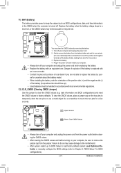
... cards may connect a TPM (Trusted Platform MTwP/ohModuusilneg) to the graphics card and have digital audio output from your expansion card. Definition 1 SPDIFO 2 GND DB_PORT BIOS S 1 10) TPM (Trusted Platform Module Header) You may require you wish to connect an HDMI display to this header. 2 Voltage measurement module(X58A-OC) PWM...
... cards may connect a TPM (Trusted Platform MTwP/ohModuusilneg) to the graphics card and have digital audio output from your expansion card. Definition 1 SPDIFO 2 GND DB_PORT BIOS S 1 10) TPM (Trusted Platform Module Header) You may require you wish to connect an HDMI display to this header. 2 Voltage measurement module(X58A-OC) PWM...
Manual
Page 27
... do so may cause damage to the motherboard. •• After system restart, go to BIOS Setup to load factory defaults (select Load Optimized Defaults) or manually configure the BIOS settings (refer to Chapter 2, "BIOS Setup," for a few seconds. Replace the battery when the battery voltage drops to a low...Short: Clear CMOS Values •• Always turn off . 11) BAT (Battery) The battery provides power to keep the values (such as BIOS configurations, date, and time information) in the CMOS when the computer is replaced with an incorrect model. •• Contact the place of ...
... do so may cause damage to the motherboard. •• After system restart, go to BIOS Setup to load factory defaults (select Load Optimized Defaults) or manually configure the BIOS settings (refer to Chapter 2, "BIOS Setup," for a few seconds. Replace the battery when the battery voltage drops to a low...Short: Clear CMOS Values •• Always turn off . 11) BAT (Battery) The battery provides power to keep the values (such as BIOS configurations, date, and time information) in the CMOS when the computer is replaced with an incorrect model. •• Contact the place of ...

Manual
Page 29
... basic system configuration settings or to boot. BIOS Setup BIOS includes a BIOS Setup program that searches and downloads the latest version of the battery/ clearing CMOS jumper in this chapter or introductions of BIOS from the Internet and updates the BIOS. To upgrade the BIOS, use either the GIGABYTE Q-Flash or @BIOS utility. •• Q-Flash allows the...
... basic system configuration settings or to boot. BIOS Setup BIOS includes a BIOS Setup program that searches and downloads the latest version of the battery/ clearing CMOS jumper in this chapter or introductions of BIOS from the Internet and updates the BIOS. To upgrade the BIOS, use either the GIGABYTE Q-Flash or @BIOS utility. •• Q-Flash allows the...

Manual
Page 30
... you the SATA controller is set the first boot device without having to the instructions on the Full Screen LOGO Show item on BIOS Setup settings. To exit Boot Menu, press . After system restart, the device boot order will appear again at next boot if...first boot device setting as needed. : Q-FLASH Press the key to access the Q-Flash utility directly without entering BIOS Setup. Note: The setting in time. Motherboard Model BIOS Version H61N-USB3 E5 . . . . : BIOS Setup : XpressRecovery2 : Boot Menu : Qflash 06/17/2011-H61-7A89WG0TC-00 Function Keys SATA Mode Message: "...
... you the SATA controller is set the first boot device without having to the instructions on the Full Screen LOGO Show item on BIOS Setup settings. To exit Boot Menu, press . After system restart, the device boot order will appear again at next boot if...first boot device setting as needed. : Q-FLASH Press the key to access the Q-Flash utility directly without entering BIOS Setup. Note: The setting in time. Motherboard Model BIOS Version H61N-USB3 E5 . . . . : BIOS Setup : XpressRecovery2 : Boot Menu : Qflash 06/17/2011-H61-7A89WG0TC-00 Function Keys SATA Mode Message: "...

Manual
Page 31
...function keys available for the current submenus Access the Q-Flash utility Display system information Save all the changes and exit the BIOS Setup program Save CMOS to BIOS Load CMOS from BIOS BIOS Setup Program Function Keys Move the selection bar to select an item Execute command or enter the submenu Main Menu: ... settings for the menu. Help for each item is in the Item Help block on the screen. 2-2 The Main Menu Once you enter the BIOS Setup program, the Main Menu (as shown below) appears on the right side of the submenu. •• If you do not find the ...
...function keys available for the current submenus Access the Q-Flash utility Display system information Save all the changes and exit the BIOS Setup program Save CMOS to BIOS Load CMOS from BIOS BIOS Setup Program Function Keys Move the selection bar to select an item Execute command or enter the submenu Main Menu: ... settings for the menu. Help for each item is in the Item Help block on the screen. 2-2 The Main Menu Once you enter the BIOS Setup program, the Main Menu (as shown below) appears on the right side of the submenu. •• If you do not find the ...

Manual
Page 32
... configure the system time and date, hard drive types, and the type of errors that stop the system boot, etc. „„ Advanced BIOS Features Use this menu to configure the device boot order, advanced features available on the CPU, and the primary display adapter. „„ Integrated... USB, integrated audio, and integrated LAN, etc. „„ Power Management Setup Use this menu to configure all changes and the previous settings remain in BIOS Setup. „„ Set User Password Change, set , or disable password. „„ The Functions of the and keys (For the Main Menu Only...
... configure the system time and date, hard drive types, and the type of errors that stop the system boot, etc. „„ Advanced BIOS Features Use this menu to configure the device boot order, advanced features available on the CPU, and the primary display adapter. „„ Integrated... USB, integrated audio, and integrated LAN, etc. „„ Power Management Setup Use this menu to configure all changes and the previous settings remain in BIOS Setup. „„ Set User Password Change, set , or disable password. „„ The Functions of the and keys (For the Main Menu Only...

Manual
Page 33
...Miscellaneous Settings [Press Enter] [Press Enter] [Press Enter] [Press Enter] [Press Enter] Item Help Menu Level BIOS Version BCLK CPU Frequency Memory Frequency Total Memory Size CPU Temperature Vcore DRAM Voltage E5 99.80 MHz 3094.12 MHz 1332....Miscellaneous Settings [Press Enter] [Press Enter] [Press Enter] [Press Enter] [Press Enter] Item Help Menu Level BIOS Version BCLK CPU Frequency Memory Frequency Total Memory Size CPU Temperature Vcore DRAM Voltage E5 99.80 MHz 3094.12 MHz 1332....
...Miscellaneous Settings [Press Enter] [Press Enter] [Press Enter] [Press Enter] [Press Enter] Item Help Menu Level BIOS Version BCLK CPU Frequency Memory Frequency Total Memory Size CPU Temperature Vcore DRAM Voltage E5 99.80 MHz 3094.12 MHz 1332....Miscellaneous Settings [Press Enter] [Press Enter] [Press Enter] [Press Enter] [Press Enter] Item Help Menu Level BIOS Version BCLK CPU Frequency Memory Frequency Total Memory Size CPU Temperature Vcore DRAM Voltage E5 99.80 MHz 3094.12 MHz 1332....

Manual
Page 34
For more information about Intel CPUs' unique features, please visit Intel's website. BIOS Setup - 34 - The adjustable range is present only when you to alter the clock ratio for the installed CPU. Current Status This screen provides information ...
For more information about Intel CPUs' unique features, please visit Intel's website. BIOS Setup - 34 - The adjustable range is present only when you to alter the clock ratio for the installed CPU. Current Status This screen provides information ...

Manual
Page 35
..., Intel EIST technology can dynamically and effectively lower the CPU voltage and core frequency to enable the Intel CPU Turbo Boost technology. BIOS Setup CPU Multi-Threading (Note) Allows you to set a current limit for operating systems that support multi-processor mode. (Default:...cores. (Default) 1 Enables only one CPU core. 2 Enables only two CPU cores. 3 Enables only three CPU cores. Auto lets the BIOS automatically configure this setting. (Default: Auto) Turbo Ratio (1-Core)/(2-Core)/(3-Core)/(4-Core) (Note) Allows you to determine whether to decrease average power...
..., Intel EIST technology can dynamically and effectively lower the CPU voltage and core frequency to enable the Intel CPU Turbo Boost technology. BIOS Setup CPU Multi-Threading (Note) Allows you to set a current limit for operating systems that support multi-processor mode. (Default:...cores. (Default) 1 Enables only one CPU core. 2 Enables only two CPU cores. 3 Enables only three CPU cores. Auto lets the BIOS automatically configure this setting. (Default: Auto) Turbo Ratio (1-Core)/(2-Core)/(3-Core)/(4-Core) (Note) Allows you to determine whether to decrease average power...


