Manual
Page 2
Motherboard GA-H61M-HD2 Oct. 19, 2012 Motherboard GA-H61M-HD2 Oct. 19, 2012
Motherboard GA-H61M-HD2 Oct. 19, 2012 Motherboard GA-H61M-HD2 Oct. 19, 2012
Manual
Page 3
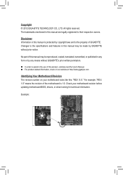
...the use of this manual may be made by copyright laws and is the property of the motherboard is 1.0. Disclaimer Information in this manual is protected by GIGABYTE without GIGABYTE's prior written permission. „„ In order to assist in any form or by ..., check on our website at: http://www.gigabyte.com Identifying Your Motherboard Revision The revision number on your motherboard revision before updating motherboard BIOS, drivers, or when looking for technical information. For example, "REV: 1.0" means the revision of GIGABYTE. Copyright © 2012 GIGA-BYTE TECHNOLOGY CO...
...the use of this manual may be made by copyright laws and is the property of the motherboard is 1.0. Disclaimer Information in this manual is protected by GIGABYTE without GIGABYTE's prior written permission. „„ In order to assist in any form or by ..., check on our website at: http://www.gigabyte.com Identifying Your Motherboard Revision The revision number on your motherboard revision before updating motherboard BIOS, drivers, or when looking for technical information. For example, "REV: 1.0" means the revision of GIGABYTE. Copyright © 2012 GIGA-BYTE TECHNOLOGY CO...
Manual
Page 4
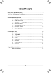
Table of Contents GA-H61M-HD2 Motherboard Layout 5 GA-H61M-HD2 Motherboard Block Diagram 6 Chapter 1 Hardware Installation 7 1-1 Installation Precautions 7 1-2 Product Specifications 8 1-3 Installing the CPU and CPU Cooler 10 1-4 Installing the Memory 11 1-5 Installing an Expansion Card 11 1-6 ...
Table of Contents GA-H61M-HD2 Motherboard Layout 5 GA-H61M-HD2 Motherboard Block Diagram 6 Chapter 1 Hardware Installation 7 1-1 Installation Precautions 7 1-2 Product Specifications 8 1-3 Installing the CPU and CPU Cooler 10 1-4 Installing the Memory 11 1-5 Installing an Expansion Card 11 1-6 ...
Manual
Page 5
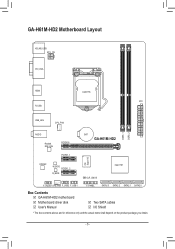
GA-H61M-HD2 Motherboard Layout KB_MS_USB ATX_12V DVI_VGA HDMI LGA1155 ATX R_USB USB_LAN CPU_FAN iTE Super I/O DDR3_1 DDR3_2 AUDIO Realtek GbE LAN PCIEX16 BAT GA-H61M-HD2 PCIEX1_1 CODEC M_BIOS PCIEX1_2 B_BIOS CLR_CMOS Intel® H61 F_AUDIO SYS_FAN F_USB2 F_USB1 F_PANEL SATA2 3 SATA2 2 SATA2 1 SATA2 0 Box Contents 55 GA-H61M-HD2 motherboard 55 Motherboard driver disk 55 User's Manual 55 Two SATA cables 55 I/O Shield * The box contents above are for reference only and the actual items shall depend on the product package you obtain. - 5 -
GA-H61M-HD2 Motherboard Layout KB_MS_USB ATX_12V DVI_VGA HDMI LGA1155 ATX R_USB USB_LAN CPU_FAN iTE Super I/O DDR3_1 DDR3_2 AUDIO Realtek GbE LAN PCIEX16 BAT GA-H61M-HD2 PCIEX1_1 CODEC M_BIOS PCIEX1_2 B_BIOS CLR_CMOS Intel® H61 F_AUDIO SYS_FAN F_USB2 F_USB1 F_PANEL SATA2 3 SATA2 2 SATA2 1 SATA2 0 Box Contents 55 GA-H61M-HD2 motherboard 55 Motherboard driver disk 55 User's Manual 55 Two SATA cables 55 I/O Shield * The box contents above are for reference only and the actual items shall depend on the product package you obtain. - 5 -
Manual
Page 6
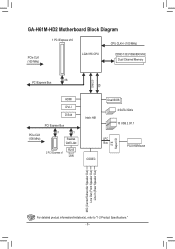
GA-H61M-HD2 Motherboard Block Diagram 1 PCI Express x16 CPU CLK+/- (100 MHz) PCIe CLK (100 MHz) LGA1155 CPU DDR3 1333/1066/800 MHz Dual Channel Memory DMI 2.0 FDI x16 PCI Express Bus HDMI DVI-I D-Sub PCI Express Bus PCIe CLK (100 MHz) x1 x1 Realtek GbE LAN 2 PCI Express x1 RJ45 LAN Intel® H61 Dual BIOS 4 SATA 3Gb/s 10 USB 2.0/1.1 LPC Bus CODEC iTE Super I/O PS/2 KB/Mouse MIC (Center/Subwoofer Speaker Out) Line Out (Front Speaker Out) Line In (Rear Speaker Out) For detailed product information/limitation(s), refer to "1-2 Product Specifications." - 6 -
GA-H61M-HD2 Motherboard Block Diagram 1 PCI Express x16 CPU CLK+/- (100 MHz) PCIe CLK (100 MHz) LGA1155 CPU DDR3 1333/1066/800 MHz Dual Channel Memory DMI 2.0 FDI x16 PCI Express Bus HDMI DVI-I D-Sub PCI Express Bus PCIe CLK (100 MHz) x1 x1 Realtek GbE LAN 2 PCI Express x1 RJ45 LAN Intel® H61 Dual BIOS 4 SATA 3Gb/s 10 USB 2.0/1.1 LPC Bus CODEC iTE Super I/O PS/2 KB/Mouse MIC (Center/Subwoofer Speaker Out) Line Out (Front Speaker Out) Line In (Rear Speaker Out) For detailed product information/limitation(s), refer to "1-2 Product Specifications." - 6 -
Manual
Page 7
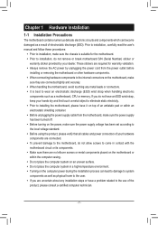
...•• Before using the product, please verify that all cables and power connectors of your dealer. These stickers are required for the motherboard. •• Prior to installation, do not allow screws to come in a high-temperature environment. •• Turning on the... computer power during the installation process can become damaged as a motherboard, CPU or memory. Prior to installation, carefully read the user's manual and follow these procedures: •• Prior to installation, make...
...•• Before using the product, please verify that all cables and power connectors of your dealer. These stickers are required for the motherboard. •• Prior to installation, do not allow screws to come in a high-temperature environment. •• Turning on the... computer power during the installation process can become damaged as a motherboard, CPU or memory. Prior to installation, carefully read the user's manual and follow these procedures: •• Prior to installation, make...
Manual
Page 9
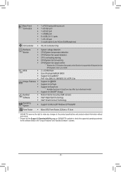
...Technology Support for Microsoft® Windows 8/7/Vista/XP Form Factor ŠŠ Micro ATX Form Factor; 22.6cm x 17.4cm * GIGABYTE reserves the right to make any changes to the product specifications and product-related information without prior notice. * Please visit the Support &... DualBIOS™ PnP 1.0a, DMI 2.0, SM BIOS 2.6, ACPI 2.0a Support for @BIOS Support for Q-Flash Support for the software listed in EasyTune may differ by motherboard model. Back Panel Connectors ŠŠ 1 x PS/2 keyboard/mouse port ŠŠ 1 x D-Sub port ŠŠ 1 x DVI-D port ŠŠ 1 ...
...Technology Support for Microsoft® Windows 8/7/Vista/XP Form Factor ŠŠ Micro ATX Form Factor; 22.6cm x 17.4cm * GIGABYTE reserves the right to make any changes to the product specifications and product-related information without prior notice. * Please visit the Support &... DualBIOS™ PnP 1.0a, DMI 2.0, SM BIOS 2.6, ACPI 2.0a Support for @BIOS Support for Q-Flash Support for the software listed in EasyTune may differ by motherboard model. Back Panel Connectors ŠŠ 1 x PS/2 keyboard/mouse port ŠŠ 1 x D-Sub port ŠŠ 1 x DVI-D port ŠŠ 1 ...
Manual
Page 10
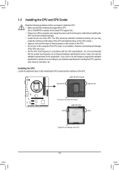
Installing the CPU Locate the alignment keys on the motherboard CPU socket and the notches on the CPU - 10 - LGA1155 CPU Socket Alignment Key Alignment Key Pin One Corner of the CPU Socket LGA1155 CPU ... computer and unplug the power cord from the power outlet before you begin to install the CPU: •• Make sure that the motherboard supports the CPU. (Go to GIGABYTE's website for the peripherals. If you wish to set beyond the standard specifications, please do so according to your hardware specifications including...
Installing the CPU Locate the alignment keys on the motherboard CPU socket and the notches on the CPU - 10 - LGA1155 CPU Socket Alignment Key Alignment Key Pin One Corner of the CPU Socket LGA1155 CPU ... computer and unplug the power cord from the power outlet before you begin to install the CPU: •• Make sure that the motherboard supports the CPU. (Go to GIGABYTE's website for the peripherals. If you wish to set beyond the standard specifications, please do so according to your hardware specifications including...
Manual
Page 11
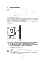
...have a foolproof design. After the memory is recommended that memory of the memory. DDR3_1 DDR3_2 Dual Channel Memory Configuration This motherboard provides two DDR3 memory sockets and supports Dual Channel Technology. Enabling Dual Channel memory mode will automatically detect the specifications and ... outlet before installing an expansion card to prevent hardware damage. - 11 - Dual Channel mode cannot be used . (Go to GIGABYTE's website for optimum performance. 1-5 Installing an Expansion Card Read the following guidelines before you begin to install the memory: ••...
...have a foolproof design. After the memory is recommended that memory of the memory. DDR3_1 DDR3_2 Dual Channel Memory Configuration This motherboard provides two DDR3 memory sockets and supports Dual Channel Technology. Enabling Dual Channel memory mode will automatically detect the specifications and ... outlet before installing an expansion card to prevent hardware damage. - 11 - Dual Channel mode cannot be used . (Go to GIGABYTE's website for optimum performance. 1-5 Installing an Expansion Card Read the following guidelines before you begin to install the memory: ••...
Manual
Page 12
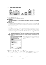
... maximum supported resolution is HDCP compliant and supports Dolby True HD and DTS HD Master Audio formats. Dual Display Configurations for the Onboard Graphics: This motherboard provides three video output ports: D-Sub, DVI-D, and HDMI. DVI-D Port (Note) The DVI-D port conforms to the DVI-D specification and supports a maximum resolution of...
... maximum supported resolution is HDCP compliant and supports Dolby True HD and DTS HD Master Audio formats. Dual Display Configurations for the Onboard Graphics: This motherboard provides three video output ports: D-Sub, DVI-D, and HDMI. DVI-D Port (Note) The DVI-D port conforms to the DVI-D specification and supports a maximum resolution of...
Manual
Page 13
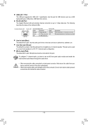
... Ethernet LAN port provides Internet connection at up to a back panel connector, first remove the cable from your device and then remove it from the motherboard. •• When removing the cable, pull it side to side to prevent an electrical short inside the cable connector. - 13 - Connection/Speed LED Activity...
... Ethernet LAN port provides Internet connection at up to a back panel connector, first remove the cable from your device and then remove it from the motherboard. •• When removing the cable, pull it side to side to prevent an electrical short inside the cable connector. - 13 - Connection/Speed LED Activity...
Manual
Page 14
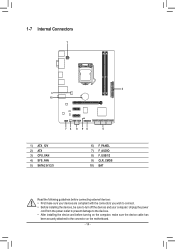
... your computer. 1-7 Internal Connectors 1 2 3 10 7 4 8 96 5 1) ATX_12V 2) ATX 3) CPU_FAN 4) SYS_FAN 5) SATA2 0/1/2/3 6) F_PANEL 7) F_AUDIO 8) F_USB1/2 9) CLR_CMOS 10) BAT Read the following guidelines before turning on the motherboard. - 14 -
... your computer. 1-7 Internal Connectors 1 2 3 10 7 4 8 96 5 1) ATX_12V 2) ATX 3) CPU_FAN 4) SYS_FAN 5) SATA2 0/1/2/3 6) F_PANEL 7) F_AUDIO 8) F_USB1/2 9) CLR_CMOS 10) BAT Read the following guidelines before turning on the motherboard. - 14 -
Manual
Page 15
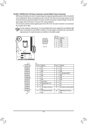
... the power supply is not connected, the computer will not start. If the 12V power connector is turned off and all the components on the motherboard. The 12V power connector mainly supplies power to all devices are properly installed. The power connector possesses a foolproof design. Connect the power supply cable to...
... the power supply is not connected, the computer will not start. If the 12V power connector is turned off and all the components on the motherboard. The 12V power connector mainly supplies power to all devices are properly installed. The power connector possesses a foolproof design. Connect the power supply cable to...
Manual
Page 16
...DEBUG PORT For optimum heat dissipation, it in damage to prevent your CPU and system from overheating. Do not place a jumper cap on this motherboard are 4-pin. Most fan headers possess a foolproof insertion design. Definition 1 GND CPU_FAN 2 +12V 3 Sense 4 Speed Control 1 SYS_FAN ... No. 1 2 3 4 5 6 7 Definition GND TXP TXN GND RXN RXP GND 1 3 SATA2 2 1 7 0 - 16 - CPU_FAN/SYS_FAN: 1 Pin No. The motherboard supports CPU fan speed control, which requires the use of a CPU fan with SATA 1.5Gb/s standard. Overheating may result in the correct orientation (the black...
...DEBUG PORT For optimum heat dissipation, it in damage to prevent your CPU and system from overheating. Do not place a jumper cap on this motherboard are 4-pin. Most fan headers possess a foolproof insertion design. Definition 1 GND CPU_FAN 2 +12V 3 Sense 4 Speed Control 1 SYS_FAN ... No. 1 2 3 4 5 6 7 Definition GND TXP TXN GND RXN RXP GND 1 3 SATA2 2 1 7 0 - 16 - CPU_FAN/SYS_FAN: 1 Pin No. The motherboard supports CPU fan speed control, which requires the use of a CPU fan with SATA 1.5Gb/s standard. Overheating may result in the correct orientation (the black...
Manual
Page 18
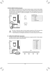
Incorrect connection between the module connector and the motherboard header will be sure to turn off your chassis front panel audio module to USB 2.0/1.1 specification. For HD Front Panel Audio: For AC'97 Front ...Panel Audio: Pin No. For information about connecting the front panel audio module that has separated connectors on both of the motherboard header. For purchasing the optional USB bracket, please contact the local dealer. 9 1 10 2 Pin No. 1 2 3 4 5 6 7 8 9 10 Definition Power (5V) Power (5V) USB DXUSB DYUSB DX...
Incorrect connection between the module connector and the motherboard header will be sure to turn off your chassis front panel audio module to USB 2.0/1.1 specification. For HD Front Panel Audio: For AC'97 Front ...Panel Audio: Pin No. For information about connecting the front panel audio module that has separated connectors on both of the motherboard header. For purchasing the optional USB bracket, please contact the local dealer. 9 1 10 2 Pin No. 1 2 3 4 5 6 7 8 9 10 Definition Power (5V) Power (5V) USB DXUSB DYUSB DX...
Manual
Page 20
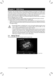
... with caution. Its major functions include conducting the Power-On Self-Test (POST) during the POST when the power is turned on the motherboard. Inadequate BIOS flashing may result in system's failure to the "Load Optimized Defaults" section in this chapter or introductions of the battery/clear...occurs, try to clear the CMOS values and reset the board to default values. (Refer to boot. To upgrade the BIOS, use either the GIGABYTE Q-Flash or @BIOS utility. •• Q-Flash allows the user to activate certain system features. BIOS includes a BIOS Setup program that ...
... with caution. Its major functions include conducting the Power-On Self-Test (POST) during the POST when the power is turned on the motherboard. Inadequate BIOS flashing may result in system's failure to the "Load Optimized Defaults" section in this chapter or introductions of the battery/clear...occurs, try to clear the CMOS values and reset the board to default values. (Refer to boot. To upgrade the BIOS, use either the GIGABYTE Q-Flash or @BIOS utility. •• Q-Flash allows the user to activate certain system features. BIOS includes a BIOS Setup program that ...
Manual
Page 27
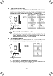
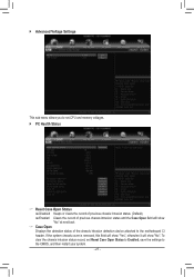
... restart your system. - 27 - `` Advanced Voltage Settings This sub-menu allows you to set Reset Case Open Status to Enabled, save the settings to the motherboard CI header.
... restart your system. - 27 - `` Advanced Voltage Settings This sub-menu allows you to set Reset Case Open Status to Enabled, save the settings to the motherboard CI header.
Manual
Page 29
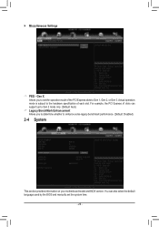
Gen X Allows you to determine whether to enhance some legacy benchmark performance. (Default: Disabled) 2-4 System This section provides information on your motherboard model and BIOS version. You can support up to Gen 2 mode only. (Default: Auto) && Legacy BenchMark Enhancement Allows you to Gen 1, Gen 2, or Gen 3. For ...
Gen X Allows you to determine whether to enhance some legacy benchmark performance. (Default: Disabled) 2-4 System This section provides information on your motherboard model and BIOS version. You can support up to Gen 2 mode only. (Default: Auto) && Legacy BenchMark Enhancement Allows you to Gen 1, Gen 2, or Gen 3. For ...

Manual
Page 37
... optical drive. Chapter 3 Drivers Installation •• Before installing the drivers, first install the operating system. •• After installing the operating system, insert the motherboard driver disk into your system and then list all the recommended drivers.
... optical drive. Chapter 3 Drivers Installation •• Before installing the drivers, first install the operating system. •• After installing the operating system, insert the motherboard driver disk into your system and then list all the recommended drivers.

Manual
Page 38
...of this product (where applicable), recycling the inner and outer packaging (including shipping containers) this product was accurate in all GIGABYTE motherboards fulfill European Union regulations for the disposal of "end of life" products, and generally improve our quality of life by... their components. The WEEE Directive specifies the treatment, collection, recycling and disposal of Hazardous Substances (RoHS) Directive Statement GIGABYTE products have been carefully selected to meet RoHS requirement. To prevent releases of harmful substances into the environment and are continuing...
...of this product (where applicable), recycling the inner and outer packaging (including shipping containers) this product was accurate in all GIGABYTE motherboards fulfill European Union regulations for the disposal of "end of life" products, and generally improve our quality of life by... their components. The WEEE Directive specifies the treatment, collection, recycling and disposal of Hazardous Substances (RoHS) Directive Statement GIGABYTE products have been carefully selected to meet RoHS requirement. To prevent releases of harmful substances into the environment and are continuing...


