
Manual
Page 1
GA-H55N-USB3 LGA1156 socket motherboard for Intel® Core™ i7 processor family/ Intel® Core™ i5 processor family/ Intel® Core™ i3 processor family User's Manual Rev. 1001 12ME-H5NUSB3-1001R
GA-H55N-USB3 LGA1156 socket motherboard for Intel® Core™ i7 processor family/ Intel® Core™ i5 processor family/ Intel® Core™ i3 processor family User's Manual Rev. 1001 12ME-H5NUSB3-1001R

Manual
Page 3
... specifications and features in any means without prior notice. For product-related information, check on our website at: http://www.gigabyte.com.tw Identifying Your Motherboard Revision The revision number on how to their respective owners. For example, "REV: 1.0" means the revision of... permission. Check your motherboard looks like this manual may be reproduced, copied, translated, transmitted, or published in this product, GIGABYTE provides the following types of documentations: For quick set-up of the product, read the User's Manual. The trademarks mentioned in...
... specifications and features in any means without prior notice. For product-related information, check on our website at: http://www.gigabyte.com.tw Identifying Your Motherboard Revision The revision number on how to their respective owners. For example, "REV: 1.0" means the revision of... permission. Check your motherboard looks like this manual may be reproduced, copied, translated, transmitted, or published in this product, GIGABYTE provides the following types of documentations: For quick set-up of the product, read the User's Manual. The trademarks mentioned in...

Manual
Page 4
Table of Contents Box Contents...6 Optional Items...6 GA-H55N-USB3 Motherboard Layout 7 GA-H55N-USB3 Motherboard Block Diagram 8 Chapter 1 Hardware Installation 9 1-1 Installation Precautions 9 1-2 Product Specifications 10 1-3 Installing the CPU and CPU Cooler 13 1-3-1 Installing the CPU 13 1-3-2 Installing the CPU ...
Table of Contents Box Contents...6 Optional Items...6 GA-H55N-USB3 Motherboard Layout 7 GA-H55N-USB3 Motherboard Block Diagram 8 Chapter 1 Hardware Installation 9 1-1 Installation Precautions 9 1-2 Product Specifications 10 1-3 Installing the CPU and CPU Cooler 13 1-3-1 Installing the CPU 13 1-3-2 Installing the CPU ...

Manual
Page 5
Chapter 3 Drivers Installation 57 3-1 Installing Chipset Drivers 57 3-2 Application Software 58 3-3 Technical Manuals 58 3-4 Contact...59 3-5 System...59 3-6 Download Center 60 3-7 New Utilities...60 Chapter 4 Unique Features 61 4-1 Xpress Recovery2 61 4-2 BIOS Update Utilities 64 4-2-1 Updating the BIOS with the Q-Flash Utility 64 4-2-2 Updating the BIOS with the @BIOS Utility 67 4-3 EasyTune 6...68 4-4 Dynamic Energy Saver™ 2 69 4-5 Q-Share...71 4-6 Smart 6™...72 4-7 Auto Green...75 Chapter 5 Appendix...77 5-1 Configuring Audio Input and Output 77 5-1-1 Configuring ...
Chapter 3 Drivers Installation 57 3-1 Installing Chipset Drivers 57 3-2 Application Software 58 3-3 Technical Manuals 58 3-4 Contact...59 3-5 System...59 3-6 Download Center 60 3-7 New Utilities...60 Chapter 4 Unique Features 61 4-1 Xpress Recovery2 61 4-2 BIOS Update Utilities 64 4-2-1 Updating the BIOS with the Q-Flash Utility 64 4-2-2 Updating the BIOS with the @BIOS Utility 67 4-3 EasyTune 6...68 4-4 Dynamic Energy Saver™ 2 69 4-5 Q-Share...71 4-6 Smart 6™...72 4-7 Auto Green...75 Chapter 5 Appendix...77 5-1 Configuring Audio Input and Output 77 5-1-1 Configuring ...

Manual
Page 6
The box contents are for reference only. Box Contents GA-H55N-USB3 motherboard Motherboard driver disk User's Manual Quick Installation Guide Two SATA cables I/O Shield • The box contents above are subject to change without notice. • The motherboard image is for reference only and the actual items shall depend on the product package you obtain. Optional Items 2-port USB 2.0 bracket (Part No. 12CR1-1UB030-5*R) 2-port SATA power cable (Part No. 12CF1-2SERPW-0*R) - 6 -
The box contents are for reference only. Box Contents GA-H55N-USB3 motherboard Motherboard driver disk User's Manual Quick Installation Guide Two SATA cables I/O Shield • The box contents above are subject to change without notice. • The motherboard image is for reference only and the actual items shall depend on the product package you obtain. Optional Items 2-port USB 2.0 bracket (Part No. 12CR1-1UB030-5*R) 2-port SATA power cable (Part No. 12CF1-2SERPW-0*R) - 6 -

Manual
Page 7
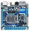
... CI CPU_FAN VGA_DVI Intel® H55 F_USB2 F_USB1 iTE IT8720 CLR_CMOS ATX_12V HDMI_SPDIF NEC D720200F1 USB_ESATA Realtek RTL8111E (Note 2) USB30_LAN SPDIF_O AUDIO F_AUDIO CODEC LGA1156 GA-H55N-USB3 DDR3_3 PHASE LED DDR3_1 DDR3_2 ATX BAT PCIEX16 M_BIOS B_BIOS (Note 3) (Note 1) Whether this feature is supported depends on the product being received. (Note 2) The...
... CI CPU_FAN VGA_DVI Intel® H55 F_USB2 F_USB1 iTE IT8720 CLR_CMOS ATX_12V HDMI_SPDIF NEC D720200F1 USB_ESATA Realtek RTL8111E (Note 2) USB30_LAN SPDIF_O AUDIO F_AUDIO CODEC LGA1156 GA-H55N-USB3 DDR3_3 PHASE LED DDR3_1 DDR3_2 ATX BAT PCIEX16 M_BIOS B_BIOS (Note 3) (Note 1) Whether this feature is supported depends on the product being received. (Note 2) The...

Manual
Page 8
GA-H55N-USB3 Motherboard Block Diagram 1 PCI Express x16 CPU CLK+/- (133 MHz) PCIe CLK (100 MHz) LGA1156 CPU DDR3 1666 (O.C.)/1333/1066/800 MHz Dual Channel Memory ...
GA-H55N-USB3 Motherboard Block Diagram 1 PCI Express x16 CPU CLK+/- (133 MHz) PCIe CLK (100 MHz) LGA1156 CPU DDR3 1666 (O.C.)/1333/1066/800 MHz Dual Channel Memory ...

Manual
Page 9
Chapter 1 Hardware Installation 1-1 Installation Precautions The motherboard contains numerous delicate electronic circuits and components which can lead to damage to the use of electrostatic discharge (ESD). These stickers are required for warranty validation. • Always remove the AC power by your hardware components are connected. • To prevent damage to the motherboard, do not allow screws to come in contact with the motherboard circuit or its components. • Make sure there are no leftover screws or metal components placed on the motherboard or within an ...
Chapter 1 Hardware Installation 1-1 Installation Precautions The motherboard contains numerous delicate electronic circuits and components which can lead to damage to the use of electrostatic discharge (ESD). These stickers are required for warranty validation. • Always remove the AC power by your hardware components are connected. • To prevent damage to the motherboard, do not allow screws to come in contact with the motherboard circuit or its components. • Make sure there are no leftover screws or metal components placed on the motherboard or within an ...

Manual
Page 10
...i7 series processor/Intel® Core™ i5 series processor/ Intel® Core™ i3 series processor in the LGA1156 package (Go to GIGABYTE's website for the latest CPU support list.) L3 cache varies with CPU Chipset Intel® H55 Express Chipset Memory Onboard Graphics ... DDR3 1666 (O.C.)/1333/1066/800 MHz memory modules Support for non-ECC memory modules Support for Extreme Memory Profile (XMP) memory modules (Go to GIGABYTE's website for S/PDIF Out LAN 1 x Realtek RTL8111E chip (10/100/1000 Mbit) Expansion Slots 1 x PCI Express x16...
...i7 series processor/Intel® Core™ i5 series processor/ Intel® Core™ i3 series processor in the LGA1156 package (Go to GIGABYTE's website for the latest CPU support list.) L3 cache varies with CPU Chipset Intel® H55 Express Chipset Memory Onboard Graphics ... DDR3 1666 (O.C.)/1333/1066/800 MHz memory modules Support for non-ECC memory modules Support for Extreme Memory Profile (XMP) memory modules (Go to GIGABYTE's website for S/PDIF Out LAN 1 x Realtek RTL8111E chip (10/100/1000 Mbit) Expansion Slots 1 x PCI Express x16...

Manual
Page 11
Internal w Connectors w w w w w w w w w w w Back Panel w Connectors w w w w w w w w w 1 x 24-pin ATX main power connector 1 x 4-pin ATX 12V power connector 4 x SATA 3Gb/s connectors 1 x CPU fan header 1 x system fan header 1 x front panel header 1 x front panel audio header 1 x S/PDIF Out header 2 x USB 2.0/1.1 headers 1 x debug card header 1 x chassis intrusion header 1 x clearing CMOS jumper 1 x PS/2 keyboard/mouse port 1 x D-Sub port (Note 2) 1 x DVI-D port (...
Internal w Connectors w w w w w w w w w w w Back Panel w Connectors w w w w w w w w w 1 x 24-pin ATX main power connector 1 x 4-pin ATX 12V power connector 4 x SATA 3Gb/s connectors 1 x CPU fan header 1 x system fan header 1 x front panel header 1 x front panel audio header 1 x S/PDIF Out header 2 x USB 2.0/1.1 headers 1 x debug card header 1 x chassis intrusion header 1 x clearing CMOS jumper 1 x PS/2 keyboard/mouse port 1 x D-Sub port (Note 2) 1 x DVI-D port (...

Manual
Page 12
Unique Features w w w w w w w w w w w w Bundled Software w Support for @BIOS Support for Q-Flash Support for Xpress BIOS Rescue Support for Download Center Support for Xpress Install Support for Xpress Recovery2 Support for EasyTune (Note 6) Support for Dynamic Energy Saver™ 2 Support for Smart 6™ Support for Auto Green Support for ON/OFF Charge Support for Q-Share Norton Internet Security (OEM version) Operating System w Support for Microsoft® Windows 7/Vista/XP Form Factor w Mini-ITX Form ...
Unique Features w w w w w w w w w w w w Bundled Software w Support for @BIOS Support for Q-Flash Support for Xpress BIOS Rescue Support for Download Center Support for Xpress Install Support for Xpress Recovery2 Support for EasyTune (Note 6) Support for Dynamic Energy Saver™ 2 Support for Smart 6™ Support for Auto Green Support for ON/OFF Charge Support for Q-Share Norton Internet Security (OEM version) Operating System w Support for Microsoft® Windows 7/Vista/XP Form Factor w Mini-ITX Form ...

Manual
Page 13
... the motherboard CPU socket and the notches on the computer if the CPU cooler is not recommended that the motherboard supports the CPU. (Go to GIGABYTE's website for the peripherals.
... the motherboard CPU socket and the notches on the computer if the CPU cooler is not recommended that the motherboard supports the CPU. (Go to GIGABYTE's website for the peripherals.

Manual
Page 14
Step 1: Gently press the CPU socket lever handle down on the rear grip of the socket cover and use the other to lightly replace the load plate. Hold your index finger down and away from the power outlet to prevent damage to correctly install the CPU into its locked position. Follow the steps below to the CPU. To protect the CPU socket, always replace the protective socket cover when the CPU is under the shoulder screw. When replacing the load plate, make sure to the "REMOVE" mark) and then remove the cover. (DO NOT touch socket contacts. Step 5: Push the CPU ...
Step 1: Gently press the CPU socket lever handle down on the rear grip of the socket cover and use the other to lightly replace the load plate. Hold your index finger down and away from the power outlet to prevent damage to correctly install the CPU into its locked position. Follow the steps below to the CPU. To protect the CPU socket, always replace the protective socket cover when the CPU is under the shoulder screw. When replacing the load plate, make sure to the "REMOVE" mark) and then remove the cover. (DO NOT touch socket contacts. Step 5: Push the CPU ...

Manual
Page 15
If the push pin is inserted as the example cooler.) Direction of the Arrow Sign on the Male Push Pin Male Push Pin The Top of Female Push Pin Female Push Pin Step 1: Apply an even and thin layer of thermal grease on the surface of arrow is to remove the cooler, on the contrary, is complete. Inadequately removing the CPU cooler may adhere to the CPU. Push down each push pin. Hardware Installation Check that the Male and Female push pins are joined closely. (Refer to your CPU cooler installation manual for instructions on installing the cooler.) Step 5: After the installation, ...
If the push pin is inserted as the example cooler.) Direction of the Arrow Sign on the Male Push Pin Male Push Pin The Top of Female Push Pin Female Push Pin Step 1: Apply an even and thin layer of thermal grease on the surface of arrow is to remove the cooler, on the contrary, is complete. Inadequately removing the CPU cooler may adhere to the CPU. Push down each push pin. Hardware Installation Check that the Male and Female push pins are joined closely. (Refer to your CPU cooler installation manual for instructions on installing the cooler.) Step 5: After the installation, ...

Manual
Page 16
... unable to insert the memory, switch the direction. It is recommended that memory of the same capacity, brand, speed, and chips be used . (Go to GIGABYTE's website for optimum performance. Hardware Installation - 16 - A memory module can be enabled if only one direction. Enabling Dual Channel memory mode will automatically detect the...
... unable to insert the memory, switch the direction. It is recommended that memory of the same capacity, brand, speed, and chips be used . (Go to GIGABYTE's website for optimum performance. Hardware Installation - 16 - A memory module can be enabled if only one direction. Enabling Dual Channel memory mode will automatically detect the...

Manual
Page 17
Place the memory module on this motherboard. Step 2: The clips at both ends of the memory socket. As indicated in the picture on the memory and insert it can only fit in the memory sockets. Notch DDR3 DIMM A DDR3 memory module has a notch, so it vertically into place when the memory module is securely inserted. - 17 - Spread the retaining clips at both ends of the socket will snap into the memory socket. Follow the steps below to correctly install your fingers on the top edge of the memory module. 1-4-2 Installing a Memory Before installing a memory module, make sure...
Place the memory module on this motherboard. Step 2: The clips at both ends of the memory socket. As indicated in the picture on the memory and insert it can only fit in the memory sockets. Notch DDR3 DIMM A DDR3 memory module has a notch, so it vertically into place when the memory module is securely inserted. - 17 - Spread the retaining clips at both ends of the socket will snap into the memory socket. Follow the steps below to correctly install your fingers on the top edge of the memory module. 1-4-2 Installing a Memory Before installing a memory module, make sure...

Manual
Page 18
Make sure the metal contacts on the top edge of the PCI Express slot to release the card and then pull the card straight up from the slot. After installing all expansion cards, replace the chassis cover(s). 6. Locate an expansion slot that came with the expansion card in the slot. 3. Remove the metal slot cover from the power outlet before you begin to install an expansion card: • Make sure the motherboard supports the expansion card. Secure the card's metal bracket to the chassis back panel with the slot, and press down on the card are completely inserted into the PCI ...
Make sure the metal contacts on the top edge of the PCI Express slot to release the card and then pull the card straight up from the slot. After installing all expansion cards, replace the chassis cover(s). 6. Locate an expansion slot that came with the expansion card in the slot. 3. Remove the metal slot cover from the power outlet before you begin to install an expansion card: • Make sure the motherboard supports the expansion card. Secure the card's metal bracket to the chassis back panel with the slot, and press down on the card are completely inserted into the PCI ...

Manual
Page 19
Connect a monitor that supports DVI-D connection to this port. Connect a monitor that supports D-Sub connection to this port. HDMI Port (Note 1)(Note 3) The HDMI (High-Definition Multimedia Interface) provides an all-digital audio/video interface to the default playback device. - 19 - The HDMI Technology can support a maximum resolution of 1920x1200 but the actual resolutions supported depend on the monitor being used ). 1-6 Back Panel Connectors USB 2.0/1.1 Port The USB port supports the USB 2.0/1.1 specification. D-Sub Port (Note 1) The D-Sub port supports a 15-pin...
Connect a monitor that supports DVI-D connection to this port. Connect a monitor that supports D-Sub connection to this port. HDMI Port (Note 1)(Note 3) The HDMI (High-Definition Multimedia Interface) provides an all-digital audio/video interface to the default playback device. - 19 - The HDMI Technology can support a maximum resolution of 1920x1200 but the actual resolutions supported depend on the monitor being used ). 1-6 Back Panel Connectors USB 2.0/1.1 Port The USB port supports the USB 2.0/1.1 specification. D-Sub Port (Note 1) The D-Sub port supports a 15-pin...

Manual
Page 20
Combination POST/BIOS Windows DVI-D + D-Sub Yes Yes DVI-D + HDMI No Yes HDMI + D-Sub Yes Yes eSATA 3Gb/s Port The eSATA 3Gb/s port conforms to SATA 3Gb/s standard and is compatible to 1 Gbps data rate. Connection/ Speed LED Activity LED LAN Port Connection/Speed LED: State Description Orange 1 Gbps data rate Green 100 Mbps data rate Off 10 Mbps data rate Activity LED: State Description Blinking Data transmission or receiving is occurring Off No data transmission or receiving is occurring USB 3.0/2.0 Port The USB 3.0 port supports the USB 3.0 specification and ...
Combination POST/BIOS Windows DVI-D + D-Sub Yes Yes DVI-D + HDMI No Yes HDMI + D-Sub Yes Yes eSATA 3Gb/s Port The eSATA 3Gb/s port conforms to SATA 3Gb/s standard and is compatible to 1 Gbps data rate. Connection/ Speed LED Activity LED LAN Port Connection/Speed LED: State Description Orange 1 Gbps data rate Green 100 Mbps data rate Off 10 Mbps data rate Activity LED: State Description Blinking Data transmission or receiving is occurring Off No data transmission or receiving is occurring USB 3.0/2.0 Port The USB 3.0 port supports the USB 3.0 specification and ...

Manual
Page 21
Hardware Installation Use this jack. Do not rock it straight out from the connector. Only microphones still MUST be reconfigured to perform different functions via the audio software. Mic In Jack (Pink) The default Mic in jack ( ). Microphones must be used to this audio jack for a headphone or 2-channel speaker. Line Out Jack (Green) The default line out jack. In addition to the default speakers settings, the ~ audio jacks can be connected to connect front speakers in a 4/5.1/7.1-channel audio configuration. Refer to the instructions on setting up a 2/4/5.1/7.1-...
Hardware Installation Use this jack. Do not rock it straight out from the connector. Only microphones still MUST be reconfigured to perform different functions via the audio software. Mic In Jack (Pink) The default Mic in jack ( ). Microphones must be used to this audio jack for a headphone or 2-channel speaker. Line Out Jack (Green) The default line out jack. In addition to the default speakers settings, the ~ audio jacks can be connected to connect front speakers in a 4/5.1/7.1-channel audio configuration. Refer to the instructions on setting up a 2/4/5.1/7.1-...
