Manual
Page 3
... form or by GIGABYTE without GIGABYTE's prior written permission. All rights reserved. Copyright © 2010 GIGA-BYTE TECHNOLOGY CO., LTD. For example, "REV: 1.0" means the revision of the motherboard is the property of documentations: For detailed product information, carefully read or download the information on/from the Support&Downloads\Motherboard\Technology Guide page on your motherboard revision before updating motherboard BIOS, drivers, or when looking...
... form or by GIGABYTE without GIGABYTE's prior written permission. All rights reserved. Copyright © 2010 GIGA-BYTE TECHNOLOGY CO., LTD. For example, "REV: 1.0" means the revision of the motherboard is the property of documentations: For detailed product information, carefully read or download the information on/from the Support&Downloads\Motherboard\Technology Guide page on your motherboard revision before updating motherboard BIOS, drivers, or when looking...
Manual
Page 4
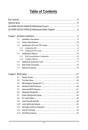
......6 Optional Items...6 GA-H55M-S2V/GA-H55M-S2 Motherboard Layout 7 GA-H55M-S2V/GA-H55M-S2 Motherboard Block Diagram 8 Chapter 1 Hardware Installation 9 1-1 Installation Precautions 9 1-2 Product Specifications 10 1-3 Installing the CPU and CPU Cooler 12 1-3-1 Installing the CPU 12 1-3-2 Installing the CPU Cooler 14 1-4 Installing the Memory 15 1-4-1 Dual Channel Memory Configuration 15 1-4-2 Installing a Memory 16 1-5 Installing an Expansion Card 17 1-6 Back Panel Connectors 18 1-7 Internal Connectors 19 Chapter 2 BIOS Setup 27 2-1 Startup Screen 28 2-2 The Main Menu 29...
......6 Optional Items...6 GA-H55M-S2V/GA-H55M-S2 Motherboard Layout 7 GA-H55M-S2V/GA-H55M-S2 Motherboard Block Diagram 8 Chapter 1 Hardware Installation 9 1-1 Installation Precautions 9 1-2 Product Specifications 10 1-3 Installing the CPU and CPU Cooler 12 1-3-1 Installing the CPU 12 1-3-2 Installing the CPU Cooler 14 1-4 Installing the Memory 15 1-4-1 Dual Channel Memory Configuration 15 1-4-2 Installing a Memory 16 1-5 Installing an Expansion Card 17 1-6 Back Panel Connectors 18 1-7 Internal Connectors 19 Chapter 2 BIOS Setup 27 2-1 Startup Screen 28 2-2 The Main Menu 29...
Manual
Page 10
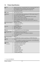
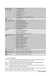
... x PCI Express x1 slot 2 x PCI slots Storage Interface Chipset: - 6 x SATA 3Gb/s connectors supporting up to the internal USB headers) Internal w 1 x 24-pin ATX main power connector Connectors w 1 x 4-pin ATX 12V power connector w 6 x SATA 3Gb/s connectors w 1 x CPU fan header w 1 x system fan header w 1 x front panel header w 1 x front panel audio header w 2 x USB 2.0/1.1 headers w 1 x clearing CMOS jumper j Only for GA-H55M-S2V. Hardware Installation - 10 - Up to 12 USB 2.0/1.1 ports (8 on...
... x PCI Express x1 slot 2 x PCI slots Storage Interface Chipset: - 6 x SATA 3Gb/s connectors supporting up to the internal USB headers) Internal w 1 x 24-pin ATX main power connector Connectors w 1 x 4-pin ATX 12V power connector w 6 x SATA 3Gb/s connectors w 1 x CPU fan header w 1 x system fan header w 1 x front panel header w 1 x front panel audio header w 2 x USB 2.0/1.1 headers w 1 x clearing CMOS jumper j Only for GA-H55M-S2V. Hardware Installation - 10 - Up to 12 USB 2.0/1.1 ports (8 on...
Manual
Page 11
... GA-H55M-S2V. (Note 1) Due to Windows 32-bit operating system limitation, when more than 4 GB of physical memory is installed, the actual memory size displayed will be less than 4 GB. (Note 2) To use the onboard DVI-D/D-Sub port, you must install an Intel CPU with integrated graphics. (Note 3) The DVI-D port does not support D-Sub connection by adapter. (Note 4) To configure 7.1-channel audio, you have to use an HD front panel audio module and enable...
... GA-H55M-S2V. (Note 1) Due to Windows 32-bit operating system limitation, when more than 4 GB of physical memory is installed, the actual memory size displayed will be less than 4 GB. (Note 2) To use the onboard DVI-D/D-Sub port, you must install an Intel CPU with integrated graphics. (Note 3) The DVI-D port does not support D-Sub connection by adapter. (Note 4) To configure 7.1-channel audio, you have to use an HD front panel audio module and enable...
Manual
Page 15
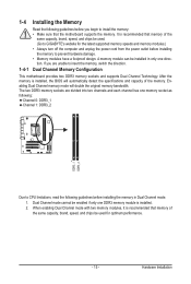
... sure that memory of the memory. When enabling Dual Channel mode with two memory modules, it is recommended that the motherboard supports the memory. Hardware Installation Dual Channel Memory Configuration This motherboard provides two DDR3 memory sockets and supports Dual Channel Technology. If you begin to insert the memory, switch the direction. After the memory is installed. 2. Dual Channel mode cannot be used . (Go to GIGABYTE's website for optimum performance. - 15 - A memory module can be used for the latest supported memory speeds and memory modules.) •...
... sure that memory of the memory. When enabling Dual Channel mode with two memory modules, it is recommended that the motherboard supports the memory. Hardware Installation Dual Channel Memory Configuration This motherboard provides two DDR3 memory sockets and supports Dual Channel Technology. If you begin to insert the memory, switch the direction. After the memory is installed. 2. Dual Channel mode cannot be used . (Go to GIGABYTE's website for optimum performance. - 15 - A memory module can be used for the latest supported memory speeds and memory modules.) •...
Manual
Page 17
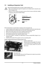
... to BIOS Setup to install an expansion card: • Make sure the motherboard supports the expansion card. 1-5 Installing an Expansion Card Read the following guidelines before installing an expansion card to release the card and then pull the card straight up from the slot. - 17 - Remove the metal slot cover from the chassis back panel. 2. Make sure the metal contacts on your expansion card in your card. Example: Installing and Removing a PCI Express Graphics Card: • Installing a Graphics Card...
... to BIOS Setup to install an expansion card: • Make sure the motherboard supports the expansion card. 1-5 Installing an Expansion Card Read the following guidelines before installing an expansion card to release the card and then pull the card straight up from the slot. - 17 - Remove the metal slot cover from the chassis back panel. 2. Make sure the metal contacts on your expansion card in your card. Example: Installing and Removing a PCI Express Graphics Card: • Installing a Graphics Card...
Manual
Page 18
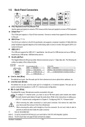
... the instructions on the monitor being used to use the onboard DVI-D/D-Sub port, you have to connect front speakers in devices such as a USB key board/mouse, USB printer, USB flash drive and etc. 1-6 Back Panel Connectors j PS/2 Keyboard and PS/2 Mouse Port Use the upper port (green) to connect a PS/2 mouse and the lower port (purple) to 1 Gbps data rate. D-Sub Port (Note 1) The D-Sub port supports a 15-pin D-Sub connector. Use this audio jack for GA-H55M-S2V (Note 1) To use an...
... the instructions on the monitor being used to use the onboard DVI-D/D-Sub port, you have to connect front speakers in devices such as a USB key board/mouse, USB printer, USB flash drive and etc. 1-6 Back Panel Connectors j PS/2 Keyboard and PS/2 Mouse Port Use the upper port (green) to connect a PS/2 mouse and the lower port (purple) to 1 Gbps data rate. D-Sub Port (Note 1) The D-Sub port supports a 15-pin D-Sub connector. Use this audio jack for GA-H55M-S2V (Note 1) To use an...
Manual
Page 25
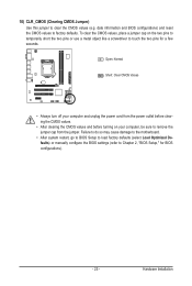
... jumper cap from the power outlet before clearing the CMOS values. • After clearing the CMOS values and before turning on the two pins to temporarily short the two pins or use a metal object like a screwdriver to Chapter 2, "BIOS Setup," for a few seconds. Failure to do so may cause damage to the motherboard. • After system restart, go to BIOS Setup to load factory defaults (select Load Optimized Defaults) or manually configure the BIOS settings...
... jumper cap from the power outlet before clearing the CMOS values. • After clearing the CMOS values and before turning on the two pins to temporarily short the two pins or use a metal object like a screwdriver to Chapter 2, "BIOS Setup," for a few seconds. Failure to do so may cause damage to the motherboard. • After system restart, go to BIOS Setup to load factory defaults (select Load Optimized Defaults) or manually configure the BIOS settings...
Manual
Page 30
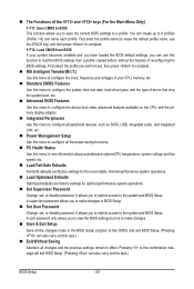
...; Integrated Peripherals Use this menu to configure all peripheral devices, such as SATA, USB, integrated audio, and integrated LAN, etc. Power Management Setup Use this menu to configure all the changes made in BIOS Setup. Set User Password Change, set , or disable password. First enter the profile name (to erase the default profile name, use the SPACE key) and then press to complete. F12: Load CMOS from BIOS If your CPU, memory, etc. Standard CMOS Features Use this task.) ...
...; Integrated Peripherals Use this menu to configure all peripheral devices, such as SATA, USB, integrated audio, and integrated LAN, etc. Power Management Setup Use this menu to configure all the changes made in BIOS Setup. Set User Password Change, set , or disable password. First enter the profile name (to erase the default profile name, use the SPACE key) and then press to complete. F12: Load CMOS from BIOS If your CPU, memory, etc. Standard CMOS Features Use this task.) ...
Manual
Page 31
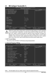
... install a memory module that supports this occurs, clear the CMOS values and reset the board to default values.) M.I .T Current Status } Advanced Frequency Settings } Advanced Memory Settings } Advanced Voltage Settings } Miscellaneous Settings [Press Enter] [Press Enter] [Press Enter] [Press Enter] [Press Enter] Item Help Menu Level BIOS Version BCLK CPU Frequency Memory Frequency Total Memory Size E1 133.27 MHz 3198.42 MHz 1332.80 MHz 1024 MB CPU Temperature PCH Temperature 45oC 40oC Vcore DRAM Voltage 1.264V...
... install a memory module that supports this occurs, clear the CMOS values and reset the board to default values.) M.I .T Current Status } Advanced Frequency Settings } Advanced Memory Settings } Advanced Voltage Settings } Miscellaneous Settings [Press Enter] [Press Enter] [Press Enter] [Press Enter] [Press Enter] Item Help Menu Level BIOS Version BCLK CPU Frequency Memory Frequency Total Memory Size E1 133.27 MHz 3198.42 MHz 1332.80 MHz 1024 MB CPU Temperature PCH Temperature 45oC 40oC Vcore DRAM Voltage 1.264V...
Manual
Page 32
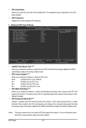
... BIOS automatically configure this setting. (Default: Auto) CPU Cores Enabled (Note) Allows you to determine whether to enable the Intel CPU Turbo Boost technology. All Enables all CPU cores. This feature only works for the installed CPU. When enabled, the CPU core frequency and voltage will be reduced during system halt state to alter the clock ratio for operating systems that supports this feature. CPU Frequency Displays the current operating CPU frequency. Advanced CPU Core Features CMOS Setup Utility-Copyright (C) 1984-2010 Award Software Advanced CPU Core...
... BIOS automatically configure this setting. (Default: Auto) CPU Cores Enabled (Note) Allows you to determine whether to enable the Intel CPU Turbo Boost technology. All Enables all CPU cores. This feature only works for the installed CPU. When enabled, the CPU core frequency and voltage will be reduced during system halt state to alter the clock ratio for operating systems that supports this feature. CPU Frequency Displays the current operating CPU frequency. Advanced CPU Core Features CMOS Setup Utility-Copyright (C) 1984-2010 Award Software Advanced CPU Core...
Manual
Page 33
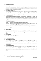
... overclocking, please wait for automated system reboot, or clear the CMOS values to reset the board to default values. (Default: Disabled) BCLK Frequency(Mhz) Allows you to manually set in system halt state. When en- ting. (Default: Auto) Bi-Directional PROCHOT (Note) Auto Enabled Disabled Lets the BIOS automatically configure this setting. (Default: Auto) CPU Thermal Monitor (Note) Enables or disables Intel CPU Thermal Monitor function, a CPU overheating protection function. This item is configurable only if the Base Clock(BCLK) Control option...
... overclocking, please wait for automated system reboot, or clear the CMOS values to reset the board to default values. (Default: Disabled) BCLK Frequency(Mhz) Allows you to manually set in system halt state. When en- ting. (Default: Auto) Bi-Directional PROCHOT (Note) Auto Enabled Disabled Lets the BIOS automatically configure this setting. (Default: Auto) CPU Thermal Monitor (Note) Enables or disables Intel CPU Thermal Monitor function, a CPU overheating protection function. This item is configurable only if the Base Clock(BCLK) Control option...
Manual
Page 38
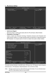
... Defaults This section provides information on the BIOS version, CPU base clock, CPU frequency, memory frequency, total memory size , CPU temperature, Chipset temperature, Vcore, and memory voltage. (Note) This item is present only if you install a CPU that supports this feature. For more information about Intel CPUs' unique features, please visit Intel's website. BIOS Setup - 38 - Miscellaneous Settings CMOS Setup Utility-Copyright (C) 1984-2010 Award Software Miscellaneous Settings Isochronous Support Virtualization Technology (Note) [Enabled] [Enabled] Item...
... Defaults This section provides information on the BIOS version, CPU base clock, CPU frequency, memory frequency, total memory size , CPU temperature, Chipset temperature, Vcore, and memory voltage. (Note) This item is present only if you install a CPU that supports this feature. For more information about Intel CPUs' unique features, please visit Intel's website. BIOS Setup - 38 - Miscellaneous Settings CMOS Setup Utility-Copyright (C) 1984-2010 Award Software Miscellaneous Settings Isochronous Support Virtualization Technology (Note) [Enabled] [Enabled] Item...
Manual
Page 39
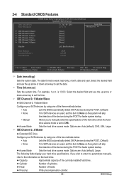
... SATA devices during the POST. (Default) • None If no SATA devices are used , set this item to set the date. Head Number of the currently installed hard drive. For example, 1 p.m. Sets the hard drive access mode. Options are : Auto (default), CHS, LBA, Large. Select the desired field and use the up arrow or down arrow key to set to manually enter the specifications of cylinders. If you to CHS. 2-4 Standard CMOS Features CMOS Setup Utility-Copyright (C) 1984-2010 Award Software Standard CMOS...
... SATA devices during the POST. (Default) • None If no SATA devices are used , set this item to set the date. Head Number of the currently installed hard drive. For example, 1 p.m. Sets the hard drive access mode. Options are : Auto (default), CHS, LBA, Large. Select the desired field and use the up arrow or down arrow key to set to manually enter the specifications of cylinders. If you to CHS. 2-4 Standard CMOS Features CMOS Setup Utility-Copyright (C) 1984-2010 Award Software Standard CMOS...
Manual
Page 41
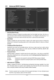
... the hard drive and to HDD Init Display First Onboard VGA On-Chip Frame Buffer Size [Press Enter] [Disabled] [Hard Disk] [CDROM] [Legacy LAN] [Setup] [Disabled] [Disabled] [Enabled] [0] [Disabled] [PCI] [Enable If No Ext PEG] [64MB+2MB for entering the BIOS Setup program. (Default) System A password is required every time the system boots, or only when you install a CPU that supports this feature. This feature allows your hard drive. Quick Boot Enables or disables the quick boot function to speed up the system boot-up or down arrow key...
... the hard drive and to HDD Init Display First Onboard VGA On-Chip Frame Buffer Size [Press Enter] [Disabled] [Hard Disk] [CDROM] [Legacy LAN] [Setup] [Disabled] [Disabled] [Enabled] [0] [Disabled] [PCI] [Enable If No Ext PEG] [64MB+2MB for entering the BIOS Setup program. (Default) System A password is required every time the system boots, or only when you install a CPU that supports this feature. This feature allows your hard drive. Quick Boot Enables or disables the quick boot function to speed up the system boot-up or down arrow key...
Manual
Page 42
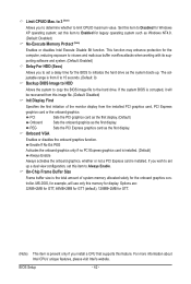
... system boots up a dual view configuration, set this item to initialize the hard drive as Windows NT4.0. (Default: Disabled) No-Execute Memory Protect (Note) Enables or disables Intel Execute Disable Bit function. MS-DOS, for display. This function may enhance protection for the computer, reducing exposure to viruses and malicious buffer overflow attacks when working with its supporting software and system. (Default: Enabled) Delay For HDD (Secs) Allows you install a CPU that supports this memory...
... system boots up a dual view configuration, set this item to initialize the hard drive as Windows NT4.0. (Default: Disabled) No-Execute Memory Protect (Note) Enables or disables Intel Execute Disable Bit function. MS-DOS, for display. This function may enhance protection for the computer, reducing exposure to viruses and malicious buffer overflow attacks when working with its supporting software and system. (Default: Enabled) Delay For HDD (Secs) Allows you install a CPU that supports this memory...
Manual
Page 43
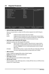
... Setup Utility-Copyright (C) 1984-2010 Award Software Integrated Peripherals SATA AHCI Mode SATA Port0-3 Native Mode USB Controllers USB Legacy Function USB Storage Function Azalia Codec Onboard H/W LAN Green LAN } SMART LAN Onboard LAN Boot ROM [IDE] [Enabled] [Enabled] [Enabled] [Enabled] [Auto] [Enabled] [Disabled] [Press Enter] [Disabled] Item Help Menu Level Move Enter: Select F5: Previous Values +/-/PU/PD: Value F10: Save F6: Fail-Safe Defaults ESC: Exit F1: General Help F7: Optimized Defaults SATA AHCI Mode (Intel H55 Chipset...
... Setup Utility-Copyright (C) 1984-2010 Award Software Integrated Peripherals SATA AHCI Mode SATA Port0-3 Native Mode USB Controllers USB Legacy Function USB Storage Function Azalia Codec Onboard H/W LAN Green LAN } SMART LAN Onboard LAN Boot ROM [IDE] [Enabled] [Enabled] [Enabled] [Enabled] [Auto] [Enabled] [Disabled] [Press Enter] [Disabled] Item Help Menu Level Move Enter: Select F5: Previous Values +/-/PU/PD: Value F10: Save F6: Fail-Safe Defaults ESC: Exit F1: General Help F7: Optimized Defaults SATA AHCI Mode (Intel H55 Chipset...

Manual
Page 44
... a normal speed of 10/100/1000 Mbps in MS-DOS mode; Cable Length Displays the approximate length of using the onboard audio, set this item to the motherboard, the Status fields of all four pairs of 10/100 Mbps in Windows mode or when the LAN Boot ROM is attached to Disabled. it will operate at a speed of wires will be disabled automatically. (Default: Disabled) SMART LAN CMOS Setup Utility-Copyright (C) 1984-2010 Award Software SMART LAN Start detecting at Port.....
... a normal speed of 10/100/1000 Mbps in MS-DOS mode; Cable Length Displays the approximate length of using the onboard audio, set this item to the motherboard, the Status fields of all four pairs of 10/100 Mbps in Windows mode or when the LAN Boot ROM is attached to Disabled. it will operate at a speed of wires will be disabled automatically. (Default: Disabled) SMART LAN CMOS Setup Utility-Copyright (C) 1984-2010 Award Software SMART LAN Start detecting at Port.....
Manual
Page 61
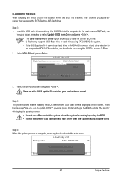
... size : 0 ESC:Reset Free size : 0 F10:Power Off 3. Unique Features Insert the USB flash drive containing the BIOS file into the computer. Make sure the BIOS update file matches your motherboard model. Select HDD 0-0 and press . B. Updating the BIOS When updating the BIOS, choose the location where the BIOS file is saved to a hard drive in RAID/AHCI mode or a hard drive attached to an independent IDE/SATA controller, use the up or down arrow key to select Update BIOS from Drive Save BIOS to begin the BIOS update. In the main menu...
... size : 0 ESC:Reset Free size : 0 F10:Power Off 3. Unique Features Insert the USB flash drive containing the BIOS file into the computer. Make sure the BIOS update file matches your motherboard model. Select HDD 0-0 and press . B. Updating the BIOS When updating the BIOS, choose the location where the BIOS file is saved to a hard drive in RAID/AHCI mode or a hard drive attached to an independent IDE/SATA controller, use the up or down arrow key to select Update BIOS from Drive Save BIOS to begin the BIOS update. In the main menu...
Manual
Page 73
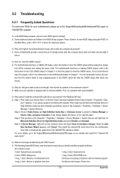
...Unknown device is still on the motherboard battery in Chapter 1 to short the jumper to clear the CMOS values. For more FAQs for hardware changes. A: Some advanced options are some BIOS options missing? A: The following Award BIOS beep code descriptions may help you identify possible computer problems. (For reference only.) 1 short: System boots successfully 1 long, 3 short: Keyboard error 2 short: CMOS setting error 1 long, 9 short: BIOS ROM error 1 long, 1 short: Memory or motherboard error Continuous long beeps: Graphics card not inserted properly 1 long, 2 short: Monitor...
...Unknown device is still on the motherboard battery in Chapter 1 to short the jumper to clear the CMOS values. For more FAQs for hardware changes. A: Some advanced options are some BIOS options missing? A: The following Award BIOS beep code descriptions may help you identify possible computer problems. (For reference only.) 1 short: System boots successfully 1 long, 3 short: Keyboard error 2 short: CMOS setting error 1 long, 9 short: BIOS ROM error 1 long, 1 short: Memory or motherboard error Continuous long beeps: Graphics card not inserted properly 1 long, 2 short: Monitor...


